Water flow Sensor
-
Starting tomorrow I will spend some time on a sidetrack of the Indigo plugin project.
I will create a 'Water Flow Sensor' based on this instructables.com project.
Background
We have a large house and warm water has to travel too long before it reaches the kitchen or master bathroom.Problem
To solve the issue we have a pump that was actived previously using a time clock.
The issue with this solution is that it is never activated when you need it or actived too long to overcome that issue ;(
When starting our home automation project the first thing I did was adding a z-wave motion sensor in the kitchen and master bathroom activating the pump when somebody entered/moved in one of these two rooms.
The issue with this solution is that it needs a complicated solution to make sure that the pump is not de-activated too early.
Apart from that, entering the kitchen or bathroom does not necessarily mean that you are going to tap warm water.Solution
Looking at the aforementioned project, aimed at saving water, I immediately thought about the following:
When I place the piezo transducer on the water pipe that comes out of the pump 'I know' when the water starts flowing and, as a result, I know that the flow needs a little help.
A signal is sent from the piezo transducer to Indigo and Indigo tells the plug/pump to do its work.
And, because this help is only needed for maybe 1 or 2 minutes (don't know yet) I can schedule an automatic off for the pump.Why will this make me happy
Less water used and I think even less electricity because instead of having the pump doing its work for nothing/nobody about 1-2 hours a day it will now do its work for maybe 10-20 minutes -
OK, this is the time to admit that this thing did not yet really take off.
The test was ok (sort of) but I wanted to use this project to take my skills to the next level.
What does that mean: I hardly soldered anything, I never designed a PCB, I never created a PCB.
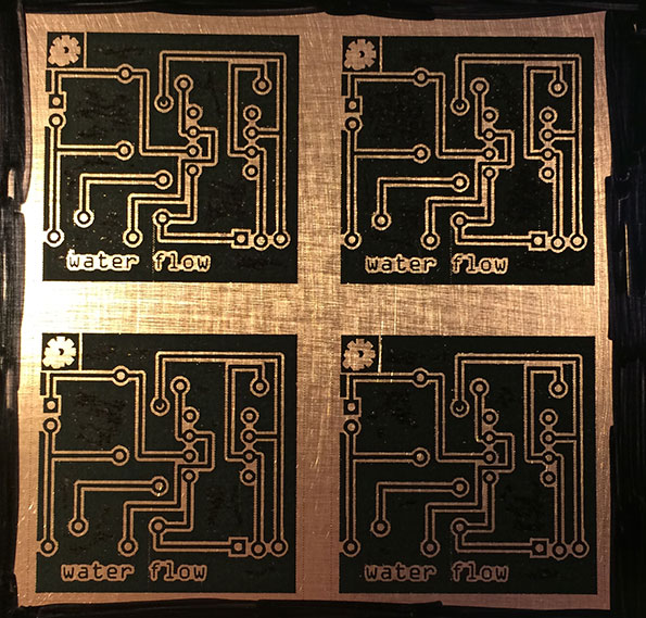
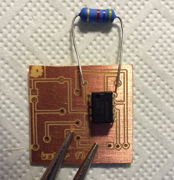
So, the next level for me is: design the thing, create the thing and solder it together.Below are some photo's to show that I really tried but there were some things that I learned today:
- designing a PCB is not easy (Fritzing was my friend today, I am sure Eagle is more powerful but one step too far for me at this time).
- designing a PCB is fun though.
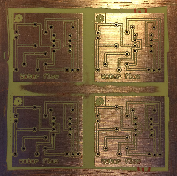
- I created the PCB using a toner printer, a laminator and Sodium Persulfate for etching.
- creating a PCB is fun, absolutely doable but time consuming.
- etching is a no brainer when you have gloves and be careful.
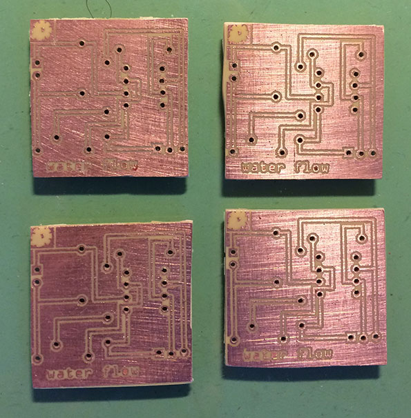
- drilling doable thanks to my Dremel.
- cutting/sawing the boards is tricky. My Dremel did a good job but I have to take better care of this.
Mistakes I made:
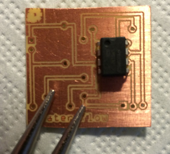
- I wanted to be friendly for the environment and the etch fluid. However, this also makes soldering more difficult when margins are too slim.
- When components go to the front side the copper goes to the backside :)
- You can buy/use 2 watt resistors but they are a (little) bit too large for using in this type of projects.
-
OK, this is the time to admit that this thing did not yet really take off.
The test was ok (sort of) but I wanted to use this project to take my skills to the next level.
What does that mean: I hardly soldered anything, I never designed a PCB, I never created a PCB.
So, the next level for me is: design the thing, create the thing and solder it together.Below are some photo's to show that I really tried but there were some things that I learned today:
- designing a PCB is not easy (Fritzing was my friend today, I am sure Eagle is more powerful but one step too far for me at this time).
- designing a PCB is fun though.
- I created the PCB using a toner printer, a laminator and Sodium Persulfate for etching.
- creating a PCB is fun, absolutely doable but time consuming.
- etching is a no brainer when you have gloves and be careful.
- drilling doable thanks to my Dremel.
- cutting/sawing the boards is tricky. My Dremel did a good job but I have to take better care of this.
Mistakes I made:
- I wanted to be friendly for the environment and the etch fluid. However, this also makes soldering more difficult when margins are too slim.
- When components go to the front side the copper goes to the backside :)
- You can buy/use 2 watt resistors but they are a (little) bit too large for using in this type of projects.
-
Thanks for sharing how to create a pcb@home. Learning by doing is the way to do it.
I haven't started the Eagle software yet.. but I'm eager.. just a little bit of MySensors-library stuff to do first....
-
Well, I have had to put the whole MySensors project on ice for a couple of months due to the fact that I am hardly home.
Hopefully end of spring I will find some time again...
Hello! It looks like you're interested in this conversation, but you don't have an account yet.
Getting fed up of having to scroll through the same posts each visit? When you register for an account, you'll always come back to exactly where you were before, and choose to be notified of new replies (either via email, or push notification). You'll also be able to save bookmarks and upvote posts to show your appreciation to other community members.
With your input, this post could be even better 💗
Register Login