3.3 or 5v tranformer for mysensors projects
-
look at this beauty that i found when look for MeanWell family:
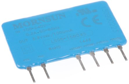
http://www.image.micros.com.pl/_dane_techniczne_auto/dc ls05-15b03s.pdf5w?
@Tmaster they require additional circuitry for filtering, look at the "TYPICAL APPLICATION" and "EMC RECOMMENDED CIRCUIT" sections.
-
@rozpruwacz said in 3.3 or 5v tranformer for mysensors projects:
@Tmaster they require additional circuitry for filtering, look at the "TYPICAL APPLICATION" and "EMC RECOMMENDED CIRCUIT" sections.
crap!
i will use an regular mini trasformer, like hi link or equivalent from a known brand with termal shutdown that hi link don't have. -
hi guys . I just discovered how some main zwave brands power their modules.
the chip used its LNK302DN and the sckematic its(adapted for 5v or 3.3v):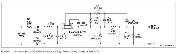
SEE PAGE 4 AND 5
http://www.farnell.com/datasheets/2059771.pdf?_ga=2.242203521.2016163251.1496347222-1734612754.1489089187That's something!:bomb:
-
hi guys . I just discovered how some main zwave brands power their modules.
the chip used its LNK302DN and the sckematic its(adapted for 5v or 3.3v):SEE PAGE 4 AND 5
http://www.farnell.com/datasheets/2059771.pdf?_ga=2.242203521.2016163251.1496347222-1734612754.1489089187That's something!:bomb:
@Tmaster , we have discussed the LNK302 chip a while ago, it may be interesting to check: https://forum.mysensors.org/search?term=lnk302&in=titlesposts
I did POC here, and it does work, but I was a bit afraid of non-isolation so I decided to use the Hi-Link, assuming it would be more safe (and less components to assembly). I'm running a couple of nodes with Hi-Link for ~2 years without a glitch.
The classic transformer approach for sure brings more isolation and safety. Also it is a good choice if you want to detect zero-cross (for AC dimmers) and measure real power consumption (by reading the real AC voltage from the transformer's AC output). On the other hand I see the bigger footprint as well as more components to assembly.
Just my two cents...
-
@Tmaster , we have discussed the LNK302 chip a while ago, it may be interesting to check: https://forum.mysensors.org/search?term=lnk302&in=titlesposts
I did POC here, and it does work, but I was a bit afraid of non-isolation so I decided to use the Hi-Link, assuming it would be more safe (and less components to assembly). I'm running a couple of nodes with Hi-Link for ~2 years without a glitch.
The classic transformer approach for sure brings more isolation and safety. Also it is a good choice if you want to detect zero-cross (for AC dimmers) and measure real power consumption (by reading the real AC voltage from the transformer's AC output). On the other hand I see the bigger footprint as well as more components to assembly.
Just my two cents...
@rvendrame said in 3.3 or 5v tranformer for mysensors projects:
On the other hand I see the bigger footprint as well as more components to assembly.
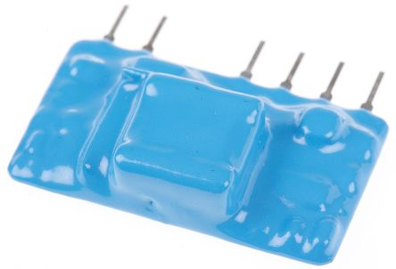
Bigger, but not always. For low-power nodes you can use very small transformers, size of such transformers with rectifier and voltage regulator comparable to Hi-Link PSUs with external curcuity, just an example on my finger:
-
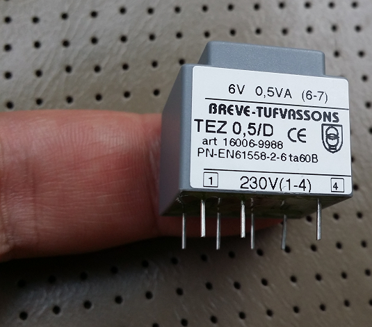
hi. i,m planing build an shutter controller with 2 relays like i already see here ,some with transformer(hlk-pm01) others tranformless(i don't trust them).
I already have many mysensors projects running but its the first one that connects directly to mains 230v and the first to be always on inside wall ,so i want it be safe.
So i search mini transformers to power that node. i find this ones below. they are like hlk-pm01 but are not chinese brand andcost around 6€http://docs-europe.electrocomponents.com/webdocs/1266/0900766b81266088.pdf
someone already use it ?
@Tmaster I have built a few in-wall switches/scene controllers that use the HLK-PM01 modules and have actually designed a circuit board for making more of them.
The board is pretty basic, but I use a standard 0.75A fuse as well as a thermal fuse on these for my high voltage protection.Another option for you are the Recom modules that some say are a much higher quality module. Compared to the HLK modules, the Recoms are a bit larger, but have things like increased space between the incoming AC power pins which for some is a concern. They come in a variety of output voltages with the 3.3v versions having a max output of 600mAn and a 400mA max for the 5V versions. Here is a data sheet link:
http://www.mouser.com/ds/2/468/RAC01_02-SC-16262.pdf -
recon psu are great,smal but expensive(12.21€) comparably with the mean well IRM-02 or IRM-01(+-5.50€) that @rozpruwacz said .
about lnk302 , i have 4 fibaro modules running for 3 to 4 years and never have problems as well.
-
Powering projects like these is always a weak point for DIY.
I have found Vigortronix power modules with a zero-detection output. Those would be very convenient for those building a dimmer. But in some parts of the world there is a tone frequency switching system on the power grid that wreaks havoc on zero crossing, as the 50 (or 60) Hz cycle is disturbed. (In our house at 23:00 sharp, you can see the switching in the light above our dining room. So I wonder how the Vigortronix modules cope with that. Also, they're a bit bigger than the Hi-Link, so almost impossible to fit in a standard EU wall box.
-
Rather than bury it in the wall, most electrical codes will require that you put your voltage converter into a suitable junction box with an easily accessible cover plate. You would then run wire from there to your point of use. That way, if your voltage converter were to fail, the damage is contained, and you can easily replace it.
-
And in theory you should also not mix mains voltage cables with low voltage ones from a safety perspective
@gohan said in 3.3 or 5v tranformer for mysensors projects:
And in theory you should also not mix mains voltage cables with low voltage ones from a safety perspective
How would you avoid that in a case like this?
-
Well that's something that should be thought during construction. Normally nothing would happen besides some EM noise that can be transferred to the low voltage wires, but if a mains wire gets damaged near a low voltage one it may burn off the small insulation and transfer 220v to your low voltage device. So the basic idea to mitigate the risk would be to use proper insulation for all the wires.
-
We are now entering the realm of where you must draw the line of how far one should go in DIY'ing their home automation.
And I think that is a very difficult discussion.
First of all, the fire risk is constantly present in the back of my head. I am now (still...) in the process of automating the lights in our house (rented, so everything has to go when we leave). The best and safest way to do so would be to run every light power cable to a central junction box with the dimmers and switches. That makes it easy to separate the mains and low voltage cables to such a degree that a fault in either will not result in a dangerous situation.But a lot of houses her in Europe, like our apartment, have all the cables in conduit embedded in concrete which would make that impossible. (I know, in Belgium, the last two decades have been different. Most of the builds in that era have been done with all the light wires to a central switch box with pulse contacts in the rooms.) So. Embed the MySensors switch or dimmer in the wall box under the light switch. I have the funny feeling the WAF would suffer if the was a lump of a box hanging next to the light switch to contain the power supply.
How do the 433MHz and Z-Wave products do it then? These are allowed inside the wall around the world. But their form factor leaves a lot to be desired. They are a pain to connect and then wrestle back inside the box. Also the little screw terminals they use do not play well with solid core wire of 2.5mm². Dilemma's!The first design of my switch was with a dropper power supply. But those have a nasty side effect. You have to be precise with the current consumption, because every mA not used in the circuit is burned off in a resistor, creating excess heat. And I use 2 relays, so that would result in about 90mA being wasted in case of both relays not being energized. Too big a risk, I think.
Now I use the Hi-Link and am running a real world like test in a wall box outside of the wall. I use the on-board temperature sensor of the RFM69 to keep track of the temperature inside the box. It runs a steady 9 degrees above ambient with an extra 5 degrees when the relay is energized. So now with a room temp of 25°C that's a tad under 40°C inside the box. Outside of the wall. With only one relay. And all that means I am still not convinced this is the way.Like I said. Dilemma's!!!!
@gohan : There is low voltage wire you can use alongside mains wiring. KNX bus cable. That has sufficient shielding and insulation.
-
The in-wall switches that I am designing do not actually control the mains with a relay. I consider them more of a scene controller that just tells my VeraPlus controller that a button was pressed. I then use that to send commands to the sonoffs that I have attached to the light, fan or other device that I want to control.
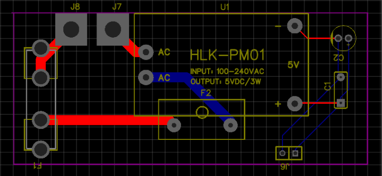
For the scene controllers, I have a standard 0.75A fuse in line with a 73°C thermal fuse for the protection in the wall. So in theory, I should be somewhat safe. The power supply board for the controller that I posted an image of in an earlier post only has the Hi Link PSU with a little bit of output filtering on the board with a fair amount of separation in the traces for the high voltage and low voltage sides. The one trace that is nearest the low voltage is the power line hot side, but it is after both fuses. On the prototypes I built before designing this board, I put a fair amount of hot glue on any high voltage side connections to prevent accidentally shorting the high voltage to the low voltage side when testing or installing.
I don't have a temp sensor on any part of the controller, but maybe that's something I can think about for a future revision of the boards.
-
I know the path you are wandering. I have been considering to do it myself. But the fact is that the in-wall boxes on your side of the pond are a fair bit bigger than here in the EU. It would be impossible for me to fit the button assembly (which would stick about 12mm into the box) with some form of battery and a 2-channel third party switching device with all the wiring inside the 50mm deep and 72mm across box.
That's why I made my own. See the pictures attached.


Right now I do not have an example of the complete assembly as it is in a full-on test.
This board of 50x50mm is the biggest I can fit inside the wall box. The idea is to first place the board inside the box and then route the wires over the pcb and connect the button/brain board last. The board is attached to the momentary switches so that closes the box neatly.
Another consideration for me is a financial one. My current actuators are de CoCo/Intertechno 433MHz ones without any delivery confirmation. There are days that messages arrive only intermittently, and for a whole house automation, that is simply not good enough. If I have to choose a new framework, other than MySensors, it would have to be Z-Wave in my opinion, as the 2.4GHz in my apartment building is very crowded (160 units). That means I have to invest in a gateway and actuators which cost a minimum of €60 each. These units can also be used as button senders, but lack the option of a signalling device (I have a RGB led option that lights between the button and the frame (I so need to make a little video of this!))
One of the top priorities in my design spec is that even with the controller down, my better half is able to control all the lighting in the house, as there are situations that I am away from home for a few days (also another reason not to go with 2.4GHz devices). All reasons to make my own design which is adaptable to a lot of situations.
And now I go and make an end to this very lengthy post. My humble apologies if I fail to make sense by jumping from topic to topic...
Salutations!
-
I know the path you are wandering. I have been considering to do it myself. But the fact is that the in-wall boxes on your side of the pond are a fair bit bigger than here in the EU. It would be impossible for me to fit the button assembly (which would stick about 12mm into the box) with some form of battery and a 2-channel third party switching device with all the wiring inside the 50mm deep and 72mm across box.
That's why I made my own. See the pictures attached.
Right now I do not have an example of the complete assembly as it is in a full-on test.
This board of 50x50mm is the biggest I can fit inside the wall box. The idea is to first place the board inside the box and then route the wires over the pcb and connect the button/brain board last. The board is attached to the momentary switches so that closes the box neatly.
Another consideration for me is a financial one. My current actuators are de CoCo/Intertechno 433MHz ones without any delivery confirmation. There are days that messages arrive only intermittently, and for a whole house automation, that is simply not good enough. If I have to choose a new framework, other than MySensors, it would have to be Z-Wave in my opinion, as the 2.4GHz in my apartment building is very crowded (160 units). That means I have to invest in a gateway and actuators which cost a minimum of €60 each. These units can also be used as button senders, but lack the option of a signalling device (I have a RGB led option that lights between the button and the frame (I so need to make a little video of this!))
One of the top priorities in my design spec is that even with the controller down, my better half is able to control all the lighting in the house, as there are situations that I am away from home for a few days (also another reason not to go with 2.4GHz devices). All reasons to make my own design which is adaptable to a lot of situations.
And now I go and make an end to this very lengthy post. My humble apologies if I fail to make sense by jumping from topic to topic...
Salutations!
You can probably buy oversized wall or junction boxes, even if they aren't available at your local home center. I did that here in the US, because I didn't feel like wrestling with the wiring (which, in my case, was 10 gauge and therefore much stiffer than the normal 12 gauge variety).
-
Well that's something that should be thought during construction. Normally nothing would happen besides some EM noise that can be transferred to the low voltage wires, but if a mains wire gets damaged near a low voltage one it may burn off the small insulation and transfer 220v to your low voltage device. So the basic idea to mitigate the risk would be to use proper insulation for all the wires.
@gohan of course isolation on low voltage cables should be good . i wonder use the nearest top wall junction box to place hi link transformer and then ,over a cat6 newtork cable ,pass 2 meters of cable to feed the sensor(5v) . easily the air conditioned or wash machine gets fire that all cable isolation fail ...
-
You can probably buy oversized wall or junction boxes, even if they aren't available at your local home center. I did that here in the US, because I didn't feel like wrestling with the wiring (which, in my case, was 10 gauge and therefore much stiffer than the normal 12 gauge variety).
Alas! The European system does not include bigger boxes. We have a standard diameter, 82mm, with two depths; 40mm and 50 mm, where 40 is the standard installed in newly built houses. Lucky for me, the building I live in was built in 1973, when they still used 50mm. This link shows a product sheet (text is Dutch, skip that...) of such a box. That's all, plus it's embedded in concrete or masonry.
There are bigger boxes, but they're only for some 3 phase sockets, you'd be unable to fit any lightswitch or cover. Useless.
This is one area I'm quite envied with the US building methods. Need an extra box? Get a saw, cut a hole and be done before morning coffee. Here you'd have to get some heavier equipment plus a good shopvac, and the new render won't be dry until next day...
-
@DavidZH said in 3.3 or 5v tranformer for mysensors projects:
This is one area I'm quite envied with the US building methods.
Well at least our houses don't fly away with a tornado (at least mine didn't) :D
Anyway I think the best approach in retrofitting an "old" house to home automation stuff is to be flexible and also include, when needed, commercial product like zwave switches that are miniaturized to fit in the size of a light switch.
Hello! It looks like you're interested in this conversation, but you don't have an account yet.
Getting fed up of having to scroll through the same posts each visit? When you register for an account, you'll always come back to exactly where you were before, and choose to be notified of new replies (either via email, or push notification). You'll also be able to save bookmarks and upvote posts to show your appreciation to other community members.
With your input, this post could be even better 💗
Register Login