💬 MyMultisensors
-
@scalz do you mind me asking where you bought PIR lens, eeprom, and most important that fancy small antenna??? Thanks
sorry to be so quiet actually :)
I buy most of my ic at electronic suppliers like Mouser, Digikey, Arrow etc.- the flash is AT25DF512C-MAHN-T . But for coincells, ota+rfm69 is a bit too much power hungry, imho..
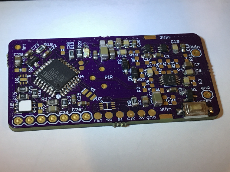
- the small pcb antenna is ANT-868-USP but it was for fun, as a simple wire antenna works as well and is cheaper.
- PIR and PIR lens are from aliexpress or ebay. PIR is LHI968. And fresnel type is 8120.
An example of link for the lens:
http://www.ebay.com/itm/10-PIECE-White-Fresnel-8120-PIR-infrared-mini-sensor-lights-small-Lenses-/142190239995?hash=item211b32e0fb:g:WsAAAOSwEHpZJnuW
-
sorry to be so quiet actually :)
I buy most of my ic at electronic suppliers like Mouser, Digikey, Arrow etc.- the flash is AT25DF512C-MAHN-T . But for coincells, ota+rfm69 is a bit too much power hungry, imho..
- the small pcb antenna is ANT-868-USP but it was for fun, as a simple wire antenna works as well and is cheaper.
- PIR and PIR lens are from aliexpress or ebay. PIR is LHI968. And fresnel type is 8120.
An example of link for the lens:
http://www.ebay.com/itm/10-PIECE-White-Fresnel-8120-PIR-infrared-mini-sensor-lights-small-Lenses-/142190239995?hash=item211b32e0fb:g:WsAAAOSwEHpZJnuW
@scalz Thank you. I do shopping at those sites as well if I do a large order, but delivery charge is just killing if I need to order 1-3 items.
I am going to try 2450 with your board. It has 600mAh so I am hoping that using eeprom is fine with this coincell. Regarding 2032, I agree with you. I have a node, which consumes 5-6uA (with watchdog) and I had to disable the LED to use it with coincell. It just drains too much energy from a low capacity battery.
Yes, simple wire would work fine, but ANT-868-USP is just looking very tidy.
-
@alexsh1
nice assembly :+1: oshpark i guess ??
I agree too, for PIR use, CR2450 is a minimum.
Well, with my tinkering and some stock in case, i usually get very quickly the free shipping..
but you can find these flash at Arrow for instance, they just need 20€ min order.
I guess you already have those, but for example,, coincell holders etc are not really cheaper at aliexpress etc..
Time to do some stock for stuff you need perhaps :) -
@alexsh1
nice assembly :+1: oshpark i guess ??
I agree too, for PIR use, CR2450 is a minimum.
Well, with my tinkering and some stock in case, i usually get very quickly the free shipping..
but you can find these flash at Arrow for instance, they just need 20€ min order.
I guess you already have those, but for example,, coincell holders etc are not really cheaper at aliexpress etc..
Time to do some stock for stuff you need perhaps :)@scalz yes, it is oshpark- I usually use them as the quality is exceptional. And typically I only need 3-4 pcbs anyway.
Unfortunately, I do not have oven and do not use smd stencil, which means the process is very long and manual. A lot of hot air fan work under the magnifying glass, but given this is not a board with too many components, it works.You should get some commission from Arrow. I have just placed my order for eeprom and some parts ;))
-
Good job! Looking forward for a assembled version for buying. (NRF, of course :grinning: )
-
-
@alexsh1 pogopads are there for this. But SI7021, and others sensors are not 5v tolerant :grimacing: You'll need to use a regulator, and perhaps get a cheap 3v/5v programmer
@Carywin source code depends what you need. you can also use some examples from MySensors website. when i'll get more time (actually busy), i'll upload mine (need to check if it needs some polishing) or some examples.
@scalz I did manage with 5V. Just de-soldered SI7021 and uploaded DualOptiboot. Other components are 5V tolerant. Having said that, I recall I did upload a different bootloader at 5V to Sensebender Micro (without nrf24l01+) without damaging SI7021.
R22 has to be changed for 330 Ohm as 1.5k was way too dark and not visible. I like bright LEDs you know :-))
-
@alexsh1 i can see the led with 1k5 :laughing: i'm using it only for debug on my side. But you're right, if you want more brightness. just be careful to not drain too much if you're using a coincell ;)
@scalz I am with you on the battery. I completely switched it off on another node running on 2032. The node is reporting very hour and has got about 4uA consumption while sleeping. :-) Probably will stay alive for a few years. However, when debugging, I like bright LEDs.
By the way, I tested the node - OPT3001 and SI7021 are working fine. Cannot test LHI968 as I still do not have some resistors. I am very satisfied. The only issue is that assembling the board is very tedious - but it is compensated by its size
-
@alexsh1 i'm very glad to hear that :+1: I'll try to upload an example for PIR pinchange with my helper lib for blindtime etc asap
@scalz I know you are currently developing a similar board on SAMD. Do you have any problems with atmega328p memory? Unfortunately, with signing and a few sensors, I'm running out of memory. On your node, I can have PIR, light, temp/hum and reed. I may struggle to combine all of them under 32kb with signing. Given that I have dualoptiboot (1.5k less) for OTA, it does not help either.
I can see your PIR setup is complex. What is it you are trying to achieve?
-
@alexsh1 my next board won't be for SAMD.
I need to check my code and what's the compil results, i don't remember exactly. but that was tight, 90% perhaps, i usually don't want to go above..
What do you mean by PIR setup is complex? -
@alexsh1 my next board won't be for SAMD.
I need to check my code and what's the compil results, i don't remember exactly. but that was tight, 90% perhaps, i usually don't want to go above..
What do you mean by PIR setup is complex? -
@alexsh1 this is a lib for helping to use PIR, could be integrated in nodemanager though, but i generally prefer to keep hands on my code, also because C code is usually more memory optimized.
So this is for handling PIR like some controllers ic do, and pinchange, with weak functions for users functions etc.
How looks my flow:/* ******************************************************************************************************************* * PIR Sensor State Machine * * Flow : sensitivity of pir sensor for noisy environment, limits tx, power saving.. * 1) NODE_SETUP : settle for PIR_SETTLE_TIME. Then 2) * 2) PIR_START : Wait/sleep for the first pulse. Then 3) * 3) PIR_SCAN : If One trigger, wait/sleep for PIR_DEFAULT_PULSES during the PIR_DEFAULT_WINDOWTIME. * If so, the motion is validated. Then 4) * Else 2) * 4) PIR_CANCEL : PIR is disabled for PIR_DEFAULT_CANCELTIME. After, this period it reports new changed state * If LOW, then 5) * Else 4) * 5) PIR_IS_BLIND: Keep PIR sensor insensitive for PIR_DEFAULT_BLINDTIME before 2) * * ******************************************************************************************************************** */ -
@alexsh1 this is a lib for helping to use PIR, could be integrated in nodemanager though, but i generally prefer to keep hands on my code, also because C code is usually more memory optimized.
So this is for handling PIR like some controllers ic do, and pinchange, with weak functions for users functions etc.
How looks my flow:/* ******************************************************************************************************************* * PIR Sensor State Machine * * Flow : sensitivity of pir sensor for noisy environment, limits tx, power saving.. * 1) NODE_SETUP : settle for PIR_SETTLE_TIME. Then 2) * 2) PIR_START : Wait/sleep for the first pulse. Then 3) * 3) PIR_SCAN : If One trigger, wait/sleep for PIR_DEFAULT_PULSES during the PIR_DEFAULT_WINDOWTIME. * If so, the motion is validated. Then 4) * Else 2) * 4) PIR_CANCEL : PIR is disabled for PIR_DEFAULT_CANCELTIME. After, this period it reports new changed state * If LOW, then 5) * Else 4) * 5) PIR_IS_BLIND: Keep PIR sensor insensitive for PIR_DEFAULT_BLINDTIME before 2) * * ******************************************************************************************************************** */@scalz this is exactly what I do not understand. For me PIR is very simple - 1 or 0, HIGH or LOW. Why treating it differently? Maybe this is very Noobs, but this is how I treat my PIRs. I may introduce 10-30 secs delay for it to settle or 30sec sleep after it has been triggered (I do not want to have extra PIR messages to my GW and controller)
-
@alexsh1
sure PIR state is 0 or 1. I'm not changing anything to this. But you can fine tune this.Do you mean you'll update each time there is a CHANGE ?? No intermediate state ??
If so, you'll waste a lot of power in useless radio TX, mcu processing, depending on days and traffic. and your batteries won't last for long!When there are people for an hour in same room, do you update each time it triggers? That can be a lot of waste!
Also why not allowing a blindtime before redecting?
In days with lot of traffic at home for example. If you already know (or the controllers could adjust this dynamically too by custom commands) that a room will be busy. It's useless and will consumes power again, to send 0 if it will retrigger in just a few seconds.So i've done sort of helper for creating intermediate states with timeouts and counters, with user defines etc.
I would only update each time there is a first HIGH. Then the node goes to unconditional sleep for 30-60 sec - there is no need to send HIGH again or LOW. After 1 min the status in Domoticz for the PIR is cleared (LOW) and the PIR is ready to send another "HIGH" if triggered.
Can Domoticz really adjust PIRs dynamically?
There is blockly stript, which helps to process "HIGH" from a PIR, but I'm not aware how this can done dynamically.Clearly, you approached this as a programmer. I have a much more simplified approach. Maybe because I'm noobs when it comes to PIRs
@scalz said in 💬 MyMultisensors:
@alexsh1
sure PIR state is 0 or 1. I'm not changing anything to this. But you can fine tune this.Do you mean you'll update each time there is a CHANGE ?? No intermediate state ??
If so, you'll waste a lot of power in useless radio TX, mcu processing, depending on days and traffic. and your batteries won't last for long!When there are people for an hour in same room, do you update each time it triggers? That can be a lot of waste!
Also why not allowing a blindtime before redecting?
In days with lot of traffic at home for example. If you already know (or the controllers could adjust this dynamically too by custom commands) that a room will be busy. It's useless and will consumes power again, to send 0 if it will retrigger in just a few seconds.So i've done sort of helper for creating intermediate states with timeouts and counters, with user defines etc.
Hello! It looks like you're interested in this conversation, but you don't have an account yet.
Getting fed up of having to scroll through the same posts each visit? When you register for an account, you'll always come back to exactly where you were before, and choose to be notified of new replies (either via email, or push notification). You'll also be able to save bookmarks and upvote posts to show your appreciation to other community members.
With your input, this post could be even better 💗
Register Login