nRF5 action!
-
About 6 hours. I asked them too if the Nordic datasheet recommendations were followed or not and if they can provide an example of how to use the module.
@mtiutiu said in nRF5 Bluetooth action!:
if they can provide an example of how to use the module
What was their answer to that, or is it still pending? I don't mind them being a black box, provided they show how to use it.
-
I requested the schematic for the cdebyte module too...but they replied: it's confidential - LOL.
@mtiutiu said in nRF5 Bluetooth action!:
I requested the schematic for the cdebyte module too...but they replied: it's confidential - LOL.
this one is funny, like if there was something special in their module :laughing:
-
@mtiutiu said in nRF5 Bluetooth action!:
if they can provide an example of how to use the module
What was their answer to that, or is it still pending? I don't mind them being a black box, provided they show how to use it.
-
Here's a photo with the lid pried off:
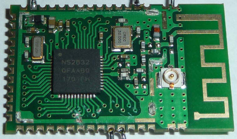
Maybe we can reconstruct what's going on just from looking at the components and the trace lines? At least for now, I'm not so concerned with the RF part. -
Here's a photo taken from the opposite angle:
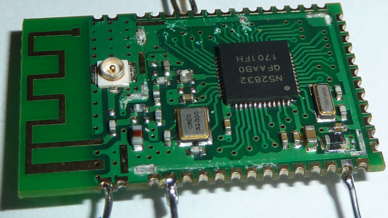
Any other photos anyone wants to see?
-
Here's the back:
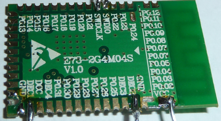
So, is it 4 layer as they claim, or only 2? Some of those vias seem rather pointless if it were only 2 layer. -
So, to Scalz's earlier point, it looks like indeed there is no capacitor already on DEC1. Regarding DEC2, it appears that there are pads and solder paste for a capacitor, but the capacitor appears to be missing! Manufacturing error?
-
@NeverDie
cool. well you just have to check continuity.
Yes this a 4layers. better for compact RF imho, else worse performance, EMI etc.. I think it's also easier to get FCC with 4layers design (not sure if this module is FCC though)My bad, i've just reread what i wrote. With nrf52 ic, I've rechecked, I'm using:
- DEC1: 100nf
- DEC2: nothing
- DEC3: 100pf
- DEC4: 1uF (and you add inductors with DCC, for DC/DC mode but it can decrease 1dB if i remember well)
@scalz
Both DEC3 and DEC4 appear to have capacitors on them. So, maybe it was the missing capacitor on DEC2 that's the reason for the module not seeming to work. I suppose I could crack another one open to see if the missing cap was a fluke or instead likely missing on most/all of them.Obviously, short of removing and testing each smd cap, I can't be sure as to what values eByte is using. I hope it doesn't come to that.... On the other hand, I could possibly remove and test the 3 on scalz's list that are of interest.
-
OK, I just pried off the lid on a different module and.... the same DEC2 cap is missing. However, according to scalz's new list that shouldn't matter.
I'll need to check continuity to see if the DEC1 cap is really not there or rather simply appearing elsewhere due to the routing.
-
OK, I just pried off the lid on a different module and.... the same DEC2 cap is missing. However, according to scalz's new list that shouldn't matter.
I'll need to check continuity to see if the DEC1 cap is really not there or rather simply appearing elsewhere due to the routing.
It turns out DEC1 is connected to a capacitor: it's the one just south of the top left capacitor in the first photo.
So, unless the cap values are just wrong, it seems that we don't need to add any more.
-
What should I check next?
-
I saw this in the MDBT42Q module datasheet, and perhaps it explains the relatively poor performance of the nRF52832 Adafruit Feather which uses the MDBT42Q.:
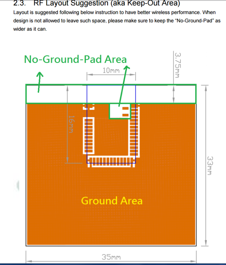
I believe the Adafruit may have a much smaller ground plane than what is being recommended here by Raytac.@NeverDie I just made the antenna on my PCB stick out so there is no fiber glass under the antenna even.
Also what is a good library for using NFC and the bluetooth peripheral of that MCU?
I came across that library:https://github.com/sandeepmistry/arduino-BLEPeripheral
but the page doesn't seem to support the BLE capability of the NRF52832
and no luck for the NFC -
@Mike_Lemo said in nRF5 Bluetooth action!:
Also If I want to change the UART pins to other pins would it work without errors or If I want to use 2 or more UARTS? same with I2C
The Chip has a lot of periphery on it. You can connect most components to pins. There is only one hardware UART, which can be connected. Please look at the Infocenter The arduino-nrf5 port is limited to things are implemented with arduino-samd by the author. This is the reason I have implemented an extension for hwPinMode() in MySensors.
Another fine thing is the implementation of Shortcuts and the PPI. You can do a lot without using the CPU.
@Mike_Lemo said in nRF5 Bluetooth action!:
Also what are the debugging options available sins the RS232 is not connected to the MCU like in an arduino how would I set stop points or peek at variables values to see if the code runs as expected?
Debugging depends on your programmer and flashing tool. I think you can start by search for "openocd gdb". OpenOCD is the flashing tool in arduino-nrf5 for all supported programmers.
@d00616 said in nRF5 Bluetooth action!:
@Mike_Lemo said in nRF5 Bluetooth action!:
Also If I want to change the UART pins to other pins would it work without errors or If I want to use 2 or more UARTS? same with I2C
The Chip has a lot of periphery on it. You can connect most components to pins. There is only one hardware UART, which can be connected. Please look at the Infocenter The arduino-nrf5 port is limited to things are implemented with arduino-samd by the author. This is the reason I have implemented an extension for hwPinMode() in MySensors.
Another fine thing is the implementation of Shortcuts and the PPI. You can do a lot without using the CPU.
@Mike_Lemo said in nRF5 Bluetooth action!:
Also what are the debugging options available sins the RS232 is not connected to the MCU like in an arduino how would I set stop points or peek at variables values to see if the code runs as expected?
Debugging depends on your programmer and flashing tool. I think you can start by search for "openocd gdb". OpenOCD is the flashing tool in arduino-nrf5 for all supported programmers.
What is that MySensors thing you were talking about?
-
@NeverDie I just made the antenna on my PCB stick out so there is no fiber glass under the antenna even.
Also what is a good library for using NFC and the bluetooth peripheral of that MCU?
I came across that library:https://github.com/sandeepmistry/arduino-BLEPeripheral
but the page doesn't seem to support the BLE capability of the NRF52832
and no luck for the NFC@Mike_Lemo said in nRF5 Bluetooth action!:
I just made the antenna on my PCB stick out so there is no fiber glass under the antenna even.
Yeah, that's what I opted for on Version 2 of my breakout board for the Ebyte nRF52832 module. Seems like the cleanest solution.
The MDBT42Q is a lot smaller than the Ebyte module, so although I was bashing it for its performance on the Adafruit (which in their case may turn out to be ground plane related), that might be an acceptable trade-off for the smaller size.
You have lots of good questions. Keep asking! I'm hoping to learn from the answers too.
-
OK, here's my plan:
-
It's possible the connections on my first attempt were a bit dodgy. I'll try again, but this time soldering a fresh new module to a prototype PCB so that they won't be mechanically stressed as I interconnect wires. Not as ideal as my breakout board will be, but I'll have to make do until it arrives.
-
If it still fails to program after step #1, then I'll check to confirm whether or not the oscillators are, uh, oscillating, at the proper frequency by using an oscilliscope after powering it up. I'm assuming they are, but it's at least easy to check and then cross off the list of suspects.
-
If still no clues, then what's next? Logic probe on the two SW lines for a compare/contrast against a successful programming of a sparkfun nRF52832 board? That's sure to generate at least some palpable data as to where the problem is occurring.
I welcome other suggestions though on how to proceed. The above is just my best guess, and I'm sure others here are better at troubleshooting this than I am.
-
-
@Mike_Lemo said in nRF5 Bluetooth action!:
I just made the antenna on my PCB stick out so there is no fiber glass under the antenna even.
Yeah, that's what I opted for on Version 2 of my breakout board for the Ebyte nRF52832 module. Seems like the cleanest solution.
The MDBT42Q is a lot smaller than the Ebyte module, so although I was bashing it for its performance on the Adafruit (which in their case may turn out to be ground plane related), that might be an acceptable trade-off for the smaller size.
You have lots of good questions. Keep asking! I'm hoping to learn from the answers too.
@NeverDie said in nRF5 Bluetooth action!:
@Mike_Lemo said in nRF5 Bluetooth action!:
I just made the antenna on my PCB stick out so there is no fiber glass under the antenna even.
Yeah, that's what I opted for on Version 2 of my breakout board for the Ebyte nRF52832 module. Seems like the cleanest solution.
The MDBT42Q is a lot smaller than the Ebyte module, so although I was bashing it for its performance on the Adafruit (which in their case may turn out to be ground plane related), that might be an acceptable trade-off for the smaller size.
You have lots of good questions. Keep asking! I'm hoping to learn from the answers too.
Yeah well at least I managed to flash a blink program to my pcb and confirm that it works but now I'm planning to abanded from Arduino anyways sins alot of functionality isn't supported.
-
@NeverDie said in nRF5 Bluetooth action!:
@Mike_Lemo said in nRF5 Bluetooth action!:
I just made the antenna on my PCB stick out so there is no fiber glass under the antenna even.
Yeah, that's what I opted for on Version 2 of my breakout board for the Ebyte nRF52832 module. Seems like the cleanest solution.
The MDBT42Q is a lot smaller than the Ebyte module, so although I was bashing it for its performance on the Adafruit (which in their case may turn out to be ground plane related), that might be an acceptable trade-off for the smaller size.
You have lots of good questions. Keep asking! I'm hoping to learn from the answers too.
Yeah well at least I managed to flash a blink program to my pcb and confirm that it works but now I'm planning to abanded from Arduino anyways sins alot of functionality isn't supported.
@Mike_Lemo said in nRF5 Bluetooth action!:
sins alot of functionality isn't supported
If your abandoning from Arduino, what will you be abandoning to?
-
@Mike_Lemo said in nRF5 Bluetooth action!:
sins alot of functionality isn't supported
If your abandoning from Arduino, what will you be abandoning to?
@NeverDie said in nRF5 Bluetooth action!:
@Mike_Lemo said in nRF5 Bluetooth action!:
sins alot of functionality isn't supported
If your abandoning from Arduino, what will you be abandoning to?
Probably eclipse
-
@NeverDie said in nRF5 Bluetooth action!:
@Mike_Lemo said in nRF5 Bluetooth action!:
sins alot of functionality isn't supported
If your abandoning from Arduino, what will you be abandoning to?
Probably eclipse
@Mike_Lemo said in nRF5 Bluetooth action!:
@NeverDie said in nRF5 Bluetooth action!:
@Mike_Lemo said in nRF5 Bluetooth action!:
sins alot of functionality isn't supported
If your abandoning from Arduino, what will you be abandoning to?
Probably eclipse
I'm rather hazy on the differences. I guess that way you can use all the Nordic libraries the way they were intended?
Hello! It looks like you're interested in this conversation, but you don't have an account yet.
Getting fed up of having to scroll through the same posts each visit? When you register for an account, you'll always come back to exactly where you were before, and choose to be notified of new replies (either via email, or push notification). You'll also be able to save bookmarks and upvote posts to show your appreciation to other community members.
With your input, this post could be even better 💗
Register Login