nRF5 action!


  • Contest Winner

    @Mike_Lemo said in nRF5 Bluetooth action!:

    @d00616 It says there NFC is not useable but what if my board is NFC hardware ready? how would I use that?

    It's simple. Use that. NFC isn't enabled or disabled by the board definition. Without SoftDevice, you have to enable the NFC functionality by flashing into the UICR.

    You can define your own Board. Look into the "boards.txt" file and the "variants" folder in ~/.arduino15/packages/sandeepmistry/hardware/nRF5/0.3.0/ Most pins can be assigned to roles like SPI, I2C, UART.... Pins like NFC, RESET are fixed and analog Pins an be ordered like your needs.


  • @NeverDie where can that boards.txt file of the NRF52 thing be found?


  • @d00616 I meant is there a library or something for that? how do I approach it I'm relatively new for this 3rd party arduino programming thing and I'ts necessary for me sins I already made a PCB for a micro controller I want to use.


  • Hero Member

    @Mike_Lemo said in nRF5 Bluetooth action!:

    @NeverDie where can that boards.txt file of the NRF52 thing be found?

    On the Windows platform it's located in this directory: Program Files/Arduino/hardware/arduino/avr


  • @NeverDie I can't see the Generic nrf52 board setting


  • Hero Member

    I added the two caps that Scalz suggested for DEC1 and DEC2, but I'm still getting the same error message as before when I try to program it using the DK. Unless someone has further ideas, I may have to wait two weeks for my breakout board to arrive before I do more, as right now I'm just deadbugging this by soldering wires directly to the module.


  • Hero Member

    @Mike_Lemo said in nRF5 Bluetooth action!:

    @NeverDie I can't see the Generic nrf52 board setting

    That's all I know, so hopefully someone who knows more can chime in and offer you guidance.


  • Hero Member

    BTW, here's a picture of how the silkscreen looks and which shows DEC1 in the "DEC5" location:
    alt text


  • Hero Member

    @NeverDie said in nRF5 Bluetooth action!:

    @Mike_Lemo said in nRF5 Bluetooth action!:

    @NeverDie I can't see the Generic nrf52 board setting

    That's all I know, so hopefully someone who knows more can chime in and offer you guidance.

    Oh, I see now that @d00616 already has. Sorry, my browser didn't refresh, so I missed seeing his post.


  • Yeah he did I just preformed a local search for that arduino15 on my PC


  • Also If I want to change the UART pins to other pins would it work without errors or If I want to use 2 or more UARTS? same with I2C

    Also what are the debugging options available sins the RS232 is not connected to the MCU like in an arduino how would I set stop points or peek at variables values to see if the code runs as expected?


  • Hero Member

    @Mike_Lemo said in nRF5 Bluetooth action!:

    you should follow this schematic design if you want to get this module working.

    0_1500734955886_Schematic-MDBT42Q Demo Board.png

    There's a bunch of similar looking schematics in the nRF52832 datasheet for the nRF52832 chip itself, but I'm not sure which of them, if any, is applicable to the Ebyte module. I guess maybe Ebyte needs a demo board schematic like Raytac has. Either that, or we need a schematic of what's on the Ebyte module itself. As it stands, I think maybe there's no enough info with which to move ahead on wiring up the Ebyte module. Am I wrong? Come to think of it, I think some of the other Chinese modules I ordered from Aliexpress may also be similar "mystery" modules. 😞


  • Contest Winner

    @Mike_Lemo said in nRF5 Bluetooth action!:

    Also If I want to change the UART pins to other pins would it work without errors or If I want to use 2 or more UARTS? same with I2C

    The Chip has a lot of periphery on it. You can connect most components to pins. There is only one hardware UART, which can be connected. Please look at the Infocenter The arduino-nrf5 port is limited to things are implemented with arduino-samd by the author. This is the reason I have implemented an extension for hwPinMode() in MySensors.

    Another fine thing is the implementation of Shortcuts and the PPI. You can do a lot without using the CPU.

    @Mike_Lemo said in nRF5 Bluetooth action!:

    Also what are the debugging options available sins the RS232 is not connected to the MCU like in an arduino how would I set stop points or peek at variables values to see if the code runs as expected?

    Debugging depends on your programmer and flashing tool. I think you can start by search for "openocd gdb". OpenOCD is the flashing tool in arduino-nrf5 for all supported programmers.


  • Hero Member

    It looks as though raytec does make two modules for the nRF52832 that has a PCB antenna rather than a chip antenna: the MDBT42Q-P and the MDBT-42V-P:
    http://statics3.seeedstudio.com/assets/file/bazaar/product/MDBT42Q-Version_B.pdf
    alt text
    The MDBT-42V-P looks nice because of its small size. Anyone know where it can be purchased? All of a sudden, buying a module that comes with a proper datasheet seems appealing.


  • @NeverDie I had mine from seeed studio


  • Hero Member


  • Hero Member

    I was just now noticing that Nordic has a very convenient list of third party modules (and their dimensions) that use the Nordic nRF52832 chips: https://www.nordicsemi.com/eng/Products/3rd-Party-Bluetooth-low-energy-Modules


  • Hero Member

    FWIW, I just now sent an email to support@cdebyte.com requesting either a schematic of their E73-2G4M04S module itself or a schematic for a demo circuit, so that I may be certain about adding the appropriate hardware needed to get their module to work. I'll post if I hear anything back from them.

    By the way, in the case of Raytac, they even have their own demo board: https://raytac.blog/2017/01/24/how-to-use-raytac-mdbt42q-nordic-nrf52832-demo-board/


  • Hero Member

    I saw this in the MDBT42Q module datasheet, and perhaps it explains the relatively poor performance of the nRF52832 Adafruit Feather which uses the MDBT42Q.:
    0_1500781343573_MBDT42Q_RAYTAC_MODULE.png
    I believe the Adafruit may have a much smaller ground plane than what is being recommended here by Raytac.


  • Hardware Contributor

    @NeverDie

    I requested the schematic for the cdebyte module too...but they replied: it's confidential - LOL.


  • Hero Member

    @mtiutiu
    How long did it take them to reply to you?

    I guess we may have to reverse engineer what they did then--at least roughly--in order to use it. I'll see if I can pry the cover off and photograph what's inside. If I'm successful, then I'll post the photos so we can all look at it together.


  • Hardware Contributor

    @NeverDie

    About 6 hours. I asked them too if the Nordic datasheet recommendations were followed or not and if they can provide an example of how to use the module.


  • Hero Member

    @mtiutiu said in nRF5 Bluetooth action!:

    if they can provide an example of how to use the module

    What was their answer to that, or is it still pending? I don't mind them being a black box, provided they show how to use it.


  • Hardware Contributor

    @mtiutiu said in nRF5 Bluetooth action!:

    @NeverDie

    I requested the schematic for the cdebyte module too...but they replied: it's confidential - LOL.

    this one is funny, like if there was something special in their module 😆


  • Hardware Contributor

    @NeverDie
    Didn't replied yet. When I get an answer I'll post it here so no worries.


  • Hero Member

    Here's a photo with the lid pried off:
    0_1500809442008_photo1.jpg
    Maybe we can reconstruct what's going on just from looking at the components and the trace lines? At least for now, I'm not so concerned with the RF part.


  • Hero Member

    Here's a photo taken from the opposite angle:
    0_1500810101142_photo2.jpg

    Any other photos anyone wants to see?


  • Hero Member

    Here's the back:
    0_1500810836390_photo3.jpg
    So, is it 4 layer as they claim, or only 2? Some of those vias seem rather pointless if it were only 2 layer.


  • Hero Member

    So, to Scalz's earlier point, it looks like indeed there is no capacitor already on DEC1. Regarding DEC2, it appears that there are pads and solder paste for a capacitor, but the capacitor appears to be missing! Manufacturing error?


  • Hardware Contributor

    @NeverDie
    cool. well you just have to check continuity.
    Yes this a 4layers. better for compact RF imho, else worse performance, EMI etc.. I think it's also easier to get FCC with 4layers design (not sure if this module is FCC though)

    My bad, i've just reread what i wrote. With nrf52 ic, I've rechecked, I'm using:

    • DEC1: 100nf
    • DEC2: nothing
    • DEC3: 100pf
    • DEC4: 1uF (and you add inductors with DCC, for DC/DC mode but it can decrease 1dB if i remember well)

  • Hero Member

    @scalz
    Both DEC3 and DEC4 appear to have capacitors on them. So, maybe it was the missing capacitor on DEC2 that's the reason for the module not seeming to work. I suppose I could crack another one open to see if the missing cap was a fluke or instead likely missing on most/all of them.

    Obviously, short of removing and testing each smd cap, I can't be sure as to what values eByte is using. I hope it doesn't come to that.... On the other hand, I could possibly remove and test the 3 on scalz's list that are of interest.


  • Hero Member

    OK, I just pried off the lid on a different module and.... the same DEC2 cap is missing. However, according to scalz's new list that shouldn't matter.

    I'll need to check continuity to see if the DEC1 cap is really not there or rather simply appearing elsewhere due to the routing.


  • Hero Member

    It turns out DEC1 is connected to a capacitor: it's the one just south of the top left capacitor in the first photo.

    So, unless the cap values are just wrong, it seems that we don't need to add any more.


  • Hero Member

    What should I check next?


  • @NeverDie I just made the antenna on my PCB stick out so there is no fiber glass under the antenna even.

    Also what is a good library for using NFC and the bluetooth peripheral of that MCU?
    I came across that library:

    https://github.com/sandeepmistry/arduino-BLEPeripheral

    but the page doesn't seem to support the BLE capability of the NRF52832
    and no luck for the NFC


  • @d00616 said in nRF5 Bluetooth action!:

    @Mike_Lemo said in nRF5 Bluetooth action!:

    Also If I want to change the UART pins to other pins would it work without errors or If I want to use 2 or more UARTS? same with I2C

    The Chip has a lot of periphery on it. You can connect most components to pins. There is only one hardware UART, which can be connected. Please look at the Infocenter The arduino-nrf5 port is limited to things are implemented with arduino-samd by the author. This is the reason I have implemented an extension for hwPinMode() in MySensors.

    Another fine thing is the implementation of Shortcuts and the PPI. You can do a lot without using the CPU.

    @Mike_Lemo said in nRF5 Bluetooth action!:

    Also what are the debugging options available sins the RS232 is not connected to the MCU like in an arduino how would I set stop points or peek at variables values to see if the code runs as expected?

    Debugging depends on your programmer and flashing tool. I think you can start by search for "openocd gdb". OpenOCD is the flashing tool in arduino-nrf5 for all supported programmers.

    What is that MySensors thing you were talking about?


  • Hero Member

    @Mike_Lemo said in nRF5 Bluetooth action!:

    I just made the antenna on my PCB stick out so there is no fiber glass under the antenna even.

    Yeah, that's what I opted for on Version 2 of my breakout board for the Ebyte nRF52832 module. Seems like the cleanest solution.

    The MDBT42Q is a lot smaller than the Ebyte module, so although I was bashing it for its performance on the Adafruit (which in their case may turn out to be ground plane related), that might be an acceptable trade-off for the smaller size.

    You have lots of good questions. Keep asking! I'm hoping to learn from the answers too.


  • Hero Member

    OK, here's my plan:

    1. It's possible the connections on my first attempt were a bit dodgy. I'll try again, but this time soldering a fresh new module to a prototype PCB so that they won't be mechanically stressed as I interconnect wires. Not as ideal as my breakout board will be, but I'll have to make do until it arrives.

    2. If it still fails to program after step #1, then I'll check to confirm whether or not the oscillators are, uh, oscillating, at the proper frequency by using an oscilliscope after powering it up. I'm assuming they are, but it's at least easy to check and then cross off the list of suspects.

    3. If still no clues, then what's next? Logic probe on the two SW lines for a compare/contrast against a successful programming of a sparkfun nRF52832 board? That's sure to generate at least some palpable data as to where the problem is occurring.

    I welcome other suggestions though on how to proceed. The above is just my best guess, and I'm sure others here are better at troubleshooting this than I am.


  • @NeverDie said in nRF5 Bluetooth action!:

    @Mike_Lemo said in nRF5 Bluetooth action!:

    I just made the antenna on my PCB stick out so there is no fiber glass under the antenna even.

    Yeah, that's what I opted for on Version 2 of my breakout board for the Ebyte nRF52832 module. Seems like the cleanest solution.

    The MDBT42Q is a lot smaller than the Ebyte module, so although I was bashing it for its performance on the Adafruit (which in their case may turn out to be ground plane related), that might be an acceptable trade-off for the smaller size.

    You have lots of good questions. Keep asking! I'm hoping to learn from the answers too.

    Yeah well at least I managed to flash a blink program to my pcb and confirm that it works but now I'm planning to abanded from Arduino anyways sins alot of functionality isn't supported.


  • Hero Member

    @Mike_Lemo said in nRF5 Bluetooth action!:

    sins alot of functionality isn't supported

    If your abandoning from Arduino, what will you be abandoning to?


  • @NeverDie said in nRF5 Bluetooth action!:

    @Mike_Lemo said in nRF5 Bluetooth action!:

    sins alot of functionality isn't supported

    If your abandoning from Arduino, what will you be abandoning to?

    Probably eclipse


  • Hero Member

    @Mike_Lemo said in nRF5 Bluetooth action!:

    @NeverDie said in nRF5 Bluetooth action!:

    @Mike_Lemo said in nRF5 Bluetooth action!:

    sins alot of functionality isn't supported

    If your abandoning from Arduino, what will you be abandoning to?

    Probably eclipse

    I'm rather hazy on the differences. I guess that way you can use all the Nordic libraries the way they were intended?


  • Hardware Contributor

    Eclipse is just an IDE 😉 like Arduino IDE, or VS etc.
    I think he means he wants to leave arduino core (mysensors rely on arduino core) to use nordic sdk with other ide (like eclipse, mbed, keil etc..). Because using eclipse with arduino core won't unlock features. It still needs coding.


  • @scalz arduino.org ble library that's based on sandeepmistry's one seems very extensive.
    I believe one need pretty substantial reasons to migrate from arduino unless you are a professional developer


  • Hero Member

    Bluetooth is everywhere, and that's great, but I'm developing the impression that Bluetooth is rather arduous to program in its "native" format. Maybe this is an opportunity to build something simpler/easier that runs on top of Bluetooth, and yet can still interact with normal bluetooth devices in the native bluetooth that they understand? I think the Arduino's wide acceptance more or less proves that "easy is good."


  • @NeverDie fully agree


  • Hero Member

    @NeverDie said in nRF5 Bluetooth action!:

    OK, here's my plan:

    1. It's possible the connections on my first attempt were a bit dodgy. I'll try again, but this time soldering a fresh new module to a prototype PCB so that they won't be mechanically stressed as I interconnect wires. Not as ideal as my breakout board will be, but I'll have to make do until it arrives.

    2. If it still fails to program after step #1, then I'll check to confirm whether or not the oscillators are, uh, oscillating, at the proper frequency by using an oscilliscope after powering it up. I'm assuming they are, but it's at least easy to check and then cross off the list of suspects.

    3. If still no clues, then what's next? Logic probe on the two SW lines for a compare/contrast against a successful programming of a sparkfun nRF52832 board? That's sure to generate at least some palpable data as to where the problem is occurring.

    I welcome other suggestions though on how to proceed. The above is just my best guess, and I'm sure others here are better at troubleshooting this than I am.

    I executed step #1 of my plan with no change in results on the second attempt of programming. The module is definitely getting 3.3v power on the VCC pin.

    So, I executed step #2. I don't see any oscillation at all on the 32.7khz oscillator. The faster oscillator is mostly quiet, but it periodically gives short little bursts of activity--here's a screenshot of one:
    0_1500851438333_NewFile1.jpg
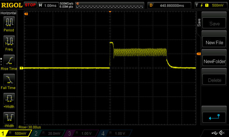
    Not sure if this is normal or not, but that's what is going on.


  • @Toyman what is that libray? I think of you refer to bel peripheral v0.3 it might not support the nrf52832 as I was asking before.


  • Hero Member

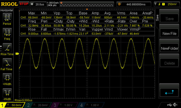
    So, for comparison, I measured the Sparkfun nRF52832 board, because (unlike the adafruit with its Raytac module), both oscillators are exposed for measurement. Unfortunately, it is already programmed, so it is not a true apples-to-apples comparison, but, anyway, the measurements were definitely different. First of all, the 32.7Khz oscillator was continuously oscillating at around 32.9Khz:
    0_1500854931082_NewFile2.jpg
    and the faster oscillator was also continuously oscillating:
    0_1500854967843_NewFile3.jpg
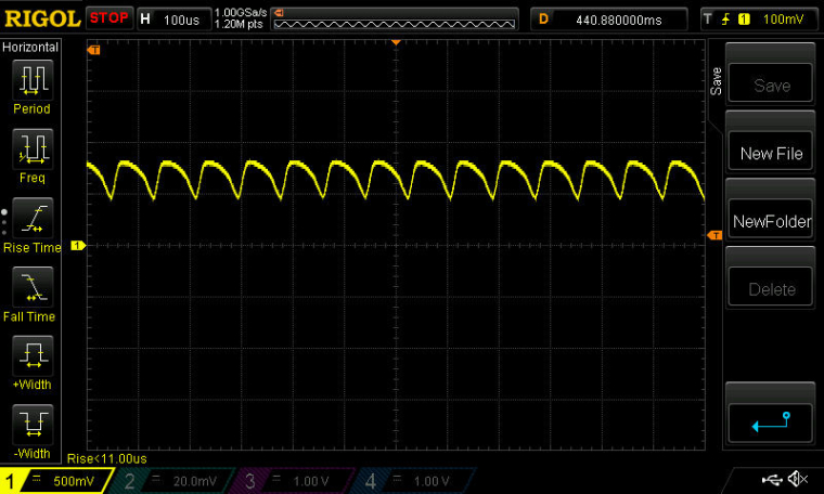
    I guess to have an apples-to-apples I would have to completely erase the firmware on the Sparkfun board.

    Anyhow, I think I'm getting the urge to order some Raytac modules.... It sounds as though they are not such a mystery.


  • Hero Member

    One thing I notice on the Ebyte module is that no RESET pin is exposed. Isn't that a bit odd?

    Also, there appears to be a typo on the silkscreen, where there are two pin 7's on the silkscreen, but probably one of them is actually pin 6.


  • Hero Member

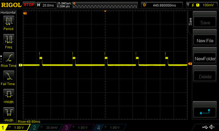
    By the way, those short bursts on activity on the Ebyte module's fast oscillator happen pretty regularly, about every 22ms or so:
    0_1500866108971_NewFile4.jpg


  • Hardware Contributor

    @NeverDie how many GND pins did you connect ?
    It might be a stupid suggestion but maybe all GND pins are not connected together ?


  • @Mike_Lemo

    http://www.arduino.org/learning/reference/ble

    This is their "homework" in anticipation of Primo launch. It does support nrf52


  • Hardware Contributor

    Ok, so after posting some questions to CDSENET Aliexpress store(in regards to the E73-2G4M04S module):

    1. Is the nrf52832 IC DEC1 pin decoupled with a 100nF capacitor as per Nordic datasheet recommendations?
    2. Is the nrf52832 IC  DEC2 pin decoupled with a 100pF capacitor as per Nordic datasheet recommendations?
    3. Are all the power pins of the nrf52832 IC decoupled as per  Nordic datasheet recommendations?
    4. Are the external components already provided so that the internal DC-DC converter can be used?
    

    I received this part of schematic:

    0_1500878901299_E73-2G4M04S.png

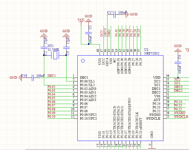
    The module that I bought is this one: CDSENET E73-2G4M04S

    I hope that it helps demystify some things in regards to this module. Maybe @NeverDie can confirm this by checking his module connections as seen in the above schematic. I'm saying this because Chinese support is well..not so user friendly in my experience and I don't know if the above schematic is indeed what they used on their module or they just provided me an example schematic of how to use the NRF52832 IC in general instead.


  • Hardware Contributor

    @Mike_Lemo @Toyman
    BLEPeripheral lib from sandeep is working fine with nrf52832, as i'm using it 😉

    Regarding the sch above, it looks like a classic circuit (in LDO mode, not surprising as DCDC mode is optional). I'm not using same values but this should work..


  • Hero Member

    They sent me two files, but I have no idea what they are, or how to open them. Maybe someone here recognizes them or can open them?
    0_1500890784640_E73-2G4M04S-PCBLIB.PCBLIB
    0_1500890793687_E73-2G4M04S-PCB-V1.0.PCBDOCPreview


  • Hero Member

    @scalz said in nRF5 Bluetooth action!:

    @Mike_Lemo @Toyman

    Regarding the sch above, it looks like a classic circuit (in LDO mode, not surprising as DCDC mode is optional). I'm not using same values but this should work..

    From what little I've read in the nRF52832 datasheet (and please do correct me if I'm wrong), the LDO mode is the "default", and is not as power efficient as the DCDC mode. Not good, as most of us probably want this for battery operation. Therefore, even if it were to work in LDO mode, what we should probably want is the DCDC mode. So, are we screwed? Or, can DCDC mode be easily applied on top of whatever they've already hardwired in the module by just adding a few more components?


  • @Toyman said in nRF5 Bluetooth action!:

    @Mike_Lemo

    http://www.arduino.org/learning/reference/ble

    This is their "homework" in anticipation of Primo launch. It does support nrf52

    @scalz said in nRF5 Bluetooth action!:

    @Mike_Lemo @Toyman
    BLEPeripheral lib from sandeep is working fine with nrf52832, as i'm using it 😉

    Regarding the sch above, it looks like a classic circuit (in LDO mode, not surprising as DCDC mode is optional). I'm not using same values but this should work..

    If you say so that's great I've downloaded that BLEPeripheral library opened one of the test and led examples and there are a few things I don't understand why would I have to define those IRQ pins and include SPI library to use the BLE on board?

    If order to send data back and forth between peripheral and central you have to use this function:?

    to read: switchCharacteristic.value();
    to write:characteristic.setValue(value, length);

    do you maybe have a little simple example to establish a connecting between central and peripheral with sending random data and peripheral and a smartphone?


  • Hardware Contributor

    @NeverDie

    For DC-DC converter you need to add some external inductor(s) and some capacitor to the DCC pin if I remember correctly. This can be observed here:
    0_1500899991486_nrf52832_dc_dc.png

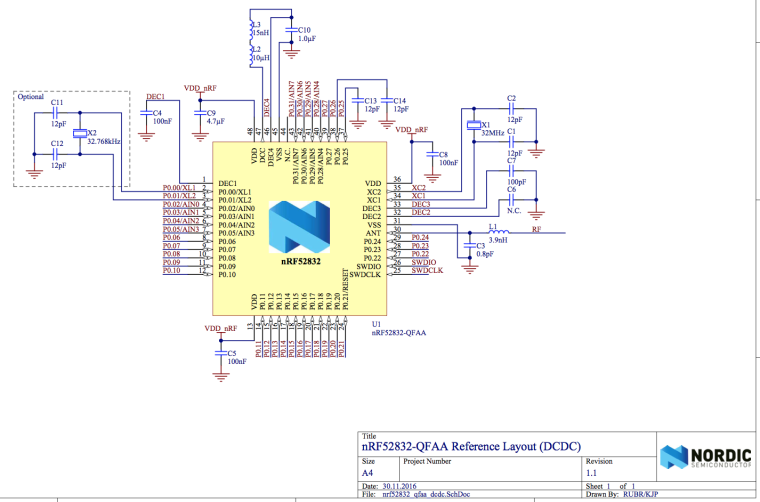
    And more than that it needs to be enabled from the SDK also.

    I didn't read the official datasheet and the recommendations from it yet...so I don't know all the implications.

    From what I've read so far this needs to be added before anything else(I think a good place is the before hook from MySensors):

    void before() {
      NRF_POWER->DCDCEN = 1;
    }
    

    And maybe this will shed some light too: https://devzone.nordicsemi.com/question/69091/a-question-about-nrf52832s-dcdc-and-ldo/


  • Hardware Contributor

    @mtiutiu there is a little confusion 🙂 this is the reference sch for nrf51. It is a bit different for nrf52.

    @Mike_Lemo no you dont need to set these pins which could be removed from the init function.
    Yes these functions are used for ble comm.
    I think sharing my unfinished code is useless (arduino & phone) if you have troubles with arduino examples. I have no time for an howto actually and little bit out of mysensors scope imho .

    The arduino examples are working fine.
    There are already written howtos at sparkfun, adafruit, blogs etc
    If you need more infos, maybe you can get more help on arduino forum too..
    And for general understanding of ble and its mechanisms (providers, services, characteristics..), you can take a look at bluetooth sig.
    Finally for custom phone app, you have to code with your preferred techno or use nordics app for simple debug


  • Hardware Contributor

    @scalz

    My bad. I corrected the initial post. Hope is all well now.

    I'm going to try this one too when I have time wt51822-s4at

    This is the cheapest of all that I found so far and yes it's not a nrf52832 but a nrf51822 - for my purpose this one is very good too. It doesn't have all the pins exposed - only 7 of them but again it should fit my general usage. I'm curious about its performance though. I'll see that when I get my hands on it. This is the official datasheet(or so it seems): https://4tronix.co.uk/picobot2/WT51822-S4AT.pdf


  • Hero Member

    @NeverDie said in nRF5 Bluetooth action!:

    They sent me two files, but I have no idea what they are, or how to open them. Maybe someone here recognizes them or can open them?
    0_1500890784640_E73-2G4M04S-PCBLIB.PCBLIB
    0_1500890793687_E73-2G4M04S-PCB-V1.0.PCBDOCPreview

    Opening the first file in notepad, I notice that it says, "PCB 6.0 Binary Library File ". I had asked Ebyte for either the module schematic or a reference design using their part, so I'm guessing this is it, in some sort of PCB CAD file.


  • Hardware Contributor

    @NeverDie

    I think they use Altium Designer and that those are files generated with it.


  • @mtiutiu if so, the free viewer is available at their site


  • Hardware Contributor

    @mtiutiu I have ordered a few of those modules too, the big question is antenna performance as it seems rather small.
    It's incredibly cheap and has enough pins to drive most of the MySensors nodes, too bad it's missing the 32K crystal for low power Bluetooth 😞


  • Hardware Contributor

    @Nca78

    I think that if we use a serial gw based on nrf24l01 pa lna variant should help cover a regular house. At least this is my intent but until then I need to prepare some test environment. And if using nrf5 repeater nodes also should help with coverage - this doesn't work for battery powered nodes I know. But I think there should be some nrf5 nodes that are powered permanently - like actuators for example.


  • Hardware Contributor

    @NeverDie

    Can you upload those files somewhere so that I can download them? I can't do that from the links you pasted here in this forum.

    I also found this altium -> kicad online converter but I don't know how well it works.


  • Hero Member

    @mtiutiu said in nRF5 Bluetooth action!:

    Can you upload those files somewhere so that I can download them? I can't do that from the links you pasted here in this forum.

    https://spaces.hightail.com/space/WMbime1pXn


  • Hardware Contributor

    @NeverDie

    Doesn't work for me so maybe it would be best to obtain a pdf or something readable for all of us from the manufacturer.


  • Hero Member

    Is no one else able to download the files either?


  • Hero Member

    @Nca78 said in nRF5 Bluetooth action!:

    @NeverDie how many GND pins did you connect ?
    It might be a stupid suggestion but maybe all GND pins are not connected together ?

    Good question. I connected to just one GND pin. However, I just now checked with a DMM, and all the exposed GND pins on the module have continuity to one another. So, based on that, I'm assuming any additional outside connections would be redundant anyway?


  • Mod

    @NeverDie said in nRF5 Bluetooth action!:

    Is no one else able to download the files either?

    From the forum, no. From hightail, yes.
    I don't know which program to open them in though.


  • Hero Member

    @mfalkvidd said in nRF5 Bluetooth action!:

    I don't know which program to open them in though

    The current theory (see above) is that maybe it's Altium Designer, which has a free viewer.


  • Hero Member

    @NeverDie said in nRF5 Bluetooth action!:

    One thing I notice on the Ebyte module is that no RESET pin is exposed. Isn't that a bit odd?

    Correction: According to the Nordic datasheet, PO.21, which is exposed on the Ebyte modle, can also serve as the reset pin. I was thrown off because Sparkfun labeled it RESET on their board's silkscreen, not "PO.21".


  • Hero Member

    @Nca78 said in nRF5 Bluetooth action!:

    I have ordered a few of those modules too,

    Do let us know if either of you are able to program it. After this Ebyte experience, I won't be taking it for granted anymore.


  • Mod

    @NeverDie not sure if it applies to this case, but at 18:04 in https://youtu.be/JXQLI-nXqmQ it is mentioned that the chip's identifier needs to be included in some list when the softdevice is compiled (or something along those lines, I am not yet familiar with the vocabulary).


  • Hero Member

    @mfalkvidd said in nRF5 Bluetooth action!:

    @NeverDie not sure if it applies to this case, but at 18:04 in https://youtu.be/JXQLI-nXqmQ it is mentioned that the chip's identifier needs to be included in some list when the softdevice is compiled (or something along those lines, I am not yet familiar with the vocabulary).

    My understanding (which may be wrong) is that in this context a "softdevice" is a veiled reference to the bluetooth stack and/or related bluetooth code, which at present the mysensors code isn't using. In any case, when I programmed both the adafruit and the sparkfun using the mysensors code, I didn't include a chip identifier in a list, nor any soft devices, and it worked anyway.


  • Hero Member

    I was thinking that maybe the Ebyte module is stuck in some kind of reset mode, but I just now checked pin P0.21 (the reset pin), and it measures high at 3.3v. This is the same as for the Sparkfun board, which I have no trouble programming. Reset is active low.


  • Contest Winner

    @NeverDie said in nRF5 Bluetooth action!:

    My understanding (which may be wrong) is that in this context a "softdevice" is a veiled reference to the bluetooth stack and/or related bluetooth code, which at present the mysensors code isn't using. In any case, when I programmed both the adafruit and the sparkfun using the mysensors code, I didn't include a chip identifier in a list, nor any soft devices, and it worked anyway.

    I haven't tested MySensors with a present SoftDevice. The drivers/NVM code (EEPROM emulation) conflicts with the DFU bootloader.

    It's better to see the SoftDevice as an Operating System providing BLE functionality and some hardware abstraction, while MySensors is directly ported to the hardware.


  • @NeverDie stupid question: did you try to power it NOT from DK board and vise versa?


  • Hero Member

    @Toyman said in nRF5 Bluetooth action!:

    @NeverDie stupid question: did you try to power it NOT from DK board and vise versa?

    Thanks for the suggestion! So far I've tried powering it from a USB 3.3v source (which is how I successfully programmed the adafruit and sparkfun boards), but I'll now try powering it from the DK and see if it makes a difference.

    By the way, I found an alternate way to confirm that the board is using the built-in LDO rather than the DCDC converter. DEC4 is the output of the LDO, and it measures 1.3v (which is also the expected voltage output by the LDO if it were active). DCC is the output of the DCDC converter, and it measures 0.0v. So, empirical confirmation of what you all inferred earlier. 🙂


  • Hero Member

    @Toyman said in nRF5 Bluetooth action!:

    @NeverDie stupid question: did you try to power it NOT from DK board and vise versa?

    Just now tried it, and unfortunately it didn't make a difference. 😞

    The actual text of the error message that I always receive is:

    c:/users/david/appdata/local/arduino15/packages/sandeepmistry/tools/gcc-arm-none-eabi/5_2-2015q4/bin/../lib/gcc/arm-none-eabi/5.2.1/../../../../arm-none-eabi/bin/ld.exe: warning: changing start of section .heap by 4 bytes
    c:/users/david/appdata/local/arduino15/packages/sandeepmistry/tools/gcc-arm-none-eabi/5_2-2015q4/bin/../lib/gcc/arm-none-eabi/5.2.1/../../../../arm-none-eabi/bin/ld.exe: warning: changing start of section .stack_dummy by 4 bytes
    Sketch uses 26932 bytes (5%) of program storage space. Maximum is 524288 bytes.
    Open On-Chip Debugger 0.10.0-dev-00254-g696fc0a (2016-04-10-10:13)
    Licensed under GNU GPL v2
    For bug reports, read
    http://openocd.org/doc/doxygen/bugs.html
    debug_level: 0
    swd
    adapter speed: 10000 kHz
    cortex_m reset_config sysresetreq
    nrf52.cpu: target state: halted
    target halted due to debug-request, current mode: Thread
    xPSR: 0x01000000 pc: 0x000008e4 msp: 0x20000400
    ** Programming Started **
    auto erase enabled
    Error: Cannot erase protected sector at 0x0
    Error: failed erasing sectors 0 to 6
    embedded:startup.tcl:454: Error: ** Programming Failed **
    in procedure 'program'
    in procedure 'program_error' called at file "embedded:startup.tcl", line 510
    at file "embedded:startup.tcl", line 454
    the selected serial port at file "embedded:startup.tcl", line 454
    does not exist or your board is not connected

    So maybe the root of the problem is that I need to do something to enable it to erase the protected sector at 0x0? That seems to be the point after which everything falls apart.


  • Mod

    @NeverDie sorry, the ID doesn't need to be in the softdevice. It needs to be in the code for the black magic probe. Might still not be related though.


  • Mod

    @NeverDie said in nRF5 Bluetooth action!:

    Error: Cannot erase protected sector at 0x0

    Could this be related to the readback protection? The video I linked before recommends issuing "monitor erase_mass" to completely reset the device and any protection.


  • Hero Member

    @mfalkvidd said in nRF5 Bluetooth action!:

    @NeverDie said in nRF5 Bluetooth action!:

    Error: Cannot erase protected sector at 0x0

    Could this be related to the readback protection? The video I linked before recommends issuing "monitor erase_mass" to completely reset the device and any protection.

    Good one! I have a hunch you may have just cracked the problem.

    I see no harm in trying a mass erase before the programming step, so I'll give it a go.


  • Hardware Contributor

    @mfalkvidd said in nRF5 Bluetooth action!:

    @NeverDie said in nRF5 Bluetooth action!:

    Is no one else able to download the files either?

    From the forum, no. From hightail, yes.

    Direct click fails. But if you press Control key while you click, to open in a new tab, then you should be able to download files from the forum 😉


  • Contest Winner

    @mfalkvidd said in nRF5 Bluetooth action!:

    Could this be related to the readback protection? The video I linked before recommends issuing "monitor erase_mass" to completely reset the device and any protection.

    This is a simple sketch for mass erasing a nRF5 MCU. Just compile it with the option a SoftDevice is present, when a SoftDevice is present:

    #include "nrf.h"
    
    void wait_for_ready()
    {
            while (NRF_NVMC->READY == NVMC_READY_READY_Busy) {
            };
    }
    
    
    void setup() {
            // Enable erasing flash
            NRF_NVMC->CONFIG = NVMC_CONFIG_WEN_Een << NVMC_CONFIG_WEN_Pos;
            wait_for_ready();
    
            // Erase Flash and UICR
            NRF_NVMC->ERASEALL = 1;
            wait_for_ready();
    
            // Disable erasing
            NRF_NVMC->CONFIG = NVMC_CONFIG_WEN_Ren << NVMC_CONFIG_WEN_Pos;
            wait_for_ready();
    
    }
    
    void loop() {
    }```

  • Hero Member

    You would think that the programmer device would just do a mass erase as part of its standard procedure, though, so it's a bit odd that it would require me to do it manually. The mass erase that Roger Clark did with his Black Magic Probe seemed nearly instant. I don't have a Black Magic Probe though.

    In any case, I can't use the above sketch to do ia mass erase because it presumes I can already load a sketch onto the target--i.e. it presumes the fundamental problem is solved already.

    What's the preferred way to do a mass erase? I seem to remember seeing a mass erase as an option in one of the Nordic utility softwares, but I don't recall now which one. Anyone happen to know?


  • Hero Member

    Looking further into it, what I may need to first do is UNLOCK the Ebyte module, which appears to be a separate step from mass erasing: https://mcuoneclipse.com/2014/10/05/unlocking-and-erasing-flash-with-segger-j-link/


  • @NeverDie may be some hints here:
    https://learn.adafruit.com/bluefruit-nrf52-feather-learning-guide/flashing-the-bootloader

    And also pay attention to their Adalink tool. The support for nrf52 was added recently.


  • Hero Member

    By switching to a Windows 10 computer, I was able to get J-link working over USB from windows. Then I opened up J-Link Command, which mostly utiizes a command line interface. It turns out that for unlocking, the nRF52836 is not on the list of devices (see below), so I simply then issued a mass erase command, which looks as though it may have worked:

    J-Link>unlock
    Syntax: unlock <DeviceName>
    ---Supported devices---
      LM3Sxxx [<Auto>]
      Kinetis
      EFM32Gxxx
      LPC5460x
    J-Link>erase
    Erasing device (nRF52832_xxAA)...
    J-Link: Flash download: Total time needed: 0.336s (Prepare: 0.064s, Compare: 0.000s, Erase: 0.263s, Program: 0.000s, Verify: 0.000s, Restore: 0.008s)
    Erasing done.
    J-Link>mem 0 100
    00000000 = FF FF FF FF FF FF FF FF FF FF FF FF FF FF FF FF
    00000010 = FF FF FF FF FF FF FF FF FF FF FF FF FF FF FF FF
    00000020 = FF FF FF FF FF FF FF FF FF FF FF FF FF FF FF FF
    00000030 = FF FF FF FF FF FF FF FF FF FF FF FF FF FF FF FF
    00000040 = FF FF FF FF FF FF FF FF FF FF FF FF FF FF FF FF
    00000050 = FF FF FF FF FF FF FF FF FF FF FF FF FF FF FF FF
    00000060 = FF FF FF FF FF FF FF FF FF FF FF FF FF FF FF FF
    00000070 = FF FF FF FF FF FF FF FF FF FF FF FF FF FF FF FF
    00000080 = FF FF FF FF FF FF FF FF FF FF FF FF FF FF FF FF
    00000090 = FF FF FF FF FF FF FF FF FF FF FF FF FF FF FF FF
    000000A0 = FF FF FF FF FF FF FF FF FF FF FF FF FF FF FF FF
    000000B0 = FF FF FF FF FF FF FF FF FF FF FF FF FF FF FF FF
    000000C0 = FF FF FF FF FF FF FF FF FF FF FF FF FF FF FF FF
    000000D0 = FF FF FF FF FF FF FF FF FF FF FF FF FF FF FF FF
    000000E0 = FF FF FF FF FF FF FF FF FF FF FF FF FF FF FF FF
    000000F0 = FF FF FF FF FF FF FF FF FF FF FF FF FF FF FF FF
    J-Link>
    

    🙂


  • Hero Member

    I received the following message from the Ebyte seller:

    Sorry that the two files are incorrect, please just ignore or delete them.
    We will send correct files later.
    
    Thank you!
    

  • Hero Member

    It worked! After doing the above mass erase, the nRF52832 Ebyte Module successfully programmed from the NRF52 DK. I uploaded the mysensors lightsensor sketch, and the serialGateway running on the NRF52 DK is receiving its messages. 🙂

    Many thanks to mfalkvidd for his mass erase suggestion and for his link to the Roger Clark youtube video, which had further mass erase commentary.

    Also, many thanks to d00616 for his excellent guide:
    https://www.openhardware.io/view/376/MySensors-NRF5-Platform
    Without that, I would have been lost on how to set anything up.

    Thanks to everyone else too who made comments and suggestions. This has been a great group effort with a successful outcome. 🙂 🙂 🙂


  • @NeverDie wow!!! Will you write a short tutorial? Is mas erase needed for EVERY time the sketch is uploaded?


  • Hardware Contributor

    That's great news @NeverDie, thank you for your efforts and thank you also to everyone who helped !
    My modules will arrive tomorrow or on Wednesday and you have saved me hours of suffering 😄


  • Hero Member

    Just now did a very quick range test, and the Ebyte nRF52832 module seems roughly comparable to the nRF52 DK for range. i.e. much better than the Adafruit nRF52832 Feather and also much better than the non-amplified nRF24L01+'s. So, whew! What a relief that is. At least for me, that means I won't need to wait for the nRF52840.

    So, now the next question is whether the Ebyte nRF52832 can be made to run in DCDC mode, instead of LDO mode, to make it more suited for battery operation. At the moment, I'm not even sure how big or small a power savings that would equate to. Anyone know?


  • Contest Winner

    @NeverDie said in nRF5 Bluetooth action!:

    So, now the next question is whether the Ebyte nRF52832 can be made to run in DCDC mode, instead of LDO mode, to make it more suited for battery operation. However, at the moment, I'm not even sure how big or small a power savings that would equate to. Anyone know?

    There is no DCDC support for ESB radio at the moment. The DCDC mode is only efficient on high current states, like enabled radio and should only enabled in an defined voltage range.


  • Hero Member

    @Toyman said in nRF5 Bluetooth action!:

    Is mas erase needed for EVERY time the sketch is uploaded?

    Roger Clark says not. I can't say for sure yet, as I haven't yet tried. I think the answer will probably turn out to be that if you aren't doing anything to specifically protect certain flash memory locations after programming it, then you would only need to do it once to undo and erase whatever came on the chip from the factory.


  • Hardware Contributor

    @NeverDie
    like said above DCDC needs to be enabled. Then, the mcu will automatically switch between LDO mode (for light loads) and DCDC mode for higher currents loads like when mcu is wake up, or during radio comms etc.. Can be interesting in some cases.
    in datasheet, DCDC mode can divide by two mcu power consumption. Side effects could be -1dB sensitivity, so it's better to filter well by using two inductors (see ref design)


  • Contest Winner

    I have found a simple way to mass erase the MCU. Select "None" as SoftDevice and use the "Burn Bootloader" function. There is an error generated but the device is erased.


Log in to reply
 

Suggested Topics

16
Online

11.2k
Users

11.1k
Topics

112.5k
Posts