MYSBootloader 1.3.0-beta.3


  • @tekka

    I've never used the clear EEPROM feature but would like to.

    I've added:

    #define MY_SPECIAL_DEBUG
    

    To my sketches. Using the latest MYSController, will the menu option 'Clear EEPROM' still do the trick, or does the application need some updates?


  • Hi,

    Is there going to be 1 and 8MHz MySBootloader hex files? 🙂

    Thanks!


  • Plugin Developer

    @tekka, I tested this bootloader and facing an issue.
    https://github.com/mysensors/MySensorsBootloaderRF24/issues/7


  • How do I do a remote reboot of a node? Node is not responding to MYSController command (I think due to changed things as with reassigning node-ID). DO I have to write a receive event or enable it somehow? Node is sleeping most time, maybe that's a problem.


  • Hardware Contributor

    I'm very interested in testing your development for the latest MYSBootloader as the bootloader for OTA updates on my new hardware designs that i'm starting to design, but i would like a stable one first to make sure my system and setup are working fine with the stable. Is the stable bootloader the one in the master branch of https://github.com/mysensors/MySensorsBootloaderRF24/tree/master. The MYSBootloader.hex file or does this still need to be compiled for use?

    Or do you happen to have a download link for the stable version, should we be using the one that you bundle together with MYSController?

    Also, @tekka - Do you advise a stable one that works for MyController.org please?


  • With this bootloader, i can not upload scetch with serial or USB.
    Where does i made a mistake?
    Is there a configuration that is specific to the bootloader?
    Thanks


  • Admin

    @Nicolas-Charrier Welcome to MySensors. Please do not post the same question in different threads. Maybe you can give additional information that help to understand what you tried so far (logs, screenshots, HW configuration, CPU frequency, etc.). Did you follow the OTA/bootloader instructions here?


  • @tekka
    I can now program my board with serial line. It's work perfectly.
    It's an issue with my serial converteur and an usb hub. The usb hub add a delay that is not compatible with the bootloader.
    Sorry for the question.
    Nico


  • Admin

    @Nicolas-Charrier Good to know, thanks for your feedback 🙂


  • Excuse me for beeing an idiot. But how do you compile the bootloader from source? Do you do it from Atmel studio or from Arduino IDE. And how is it done? When I compile it in Atmel studio it gets an base adress of 0x0000 which is wrong.

    I am used to program in assembler in Atmel studio and when I program in C i don't touch anyting else than the .c file. So some form of tutorial kind of thing would be helpful.

    Thank you


  • Hey all,

    I've compiled the bootloader and was able to install it with Arduino as ISP to a Nano. I couldn't find the lines necessary for the Nano in boards.txt so I created this:

    ##############################################################
    
    nanomysbootloader.name=Arduino Nano MYSBootloader
    
    nanomysbootloader.upload.tool=avrdude
    nanomysbootloader.upload.protocol=arduino
    
    nanomysbootloader.bootloader.tool=avrdude
    nanomysbootloader.bootloader.unlock_bits=0x3F
    nanomysbootloader.bootloader.lock_bits=0x0F
    
    nanomysbootloader.build.f_cpu=16000000L
    nanomysbootloader.build.board=AVR_NANO
    nanomysbootloader.build.core=arduino
    nanomysbootloader.build.variant=eightanaloginputs
    
    ## Arduino Nano w/ ATmega328
    ## -------------------------
    nanomysbootloader.menu.cpu.atmega328=ATmega328
    
    nanomysbootloader.menu.cpu.atmega328.upload.maximum_size=30720
    nanomysbootloader.menu.cpu.atmega328.upload.maximum_data_size=2048
    nanomysbootloader.menu.cpu.atmega328.upload.speed=115200
    
    nanomysbootloader.menu.cpu.atmega328.bootloader.low_fuses=0xFF
    nanomysbootloader.menu.cpu.atmega328.bootloader.high_fuses=0xDA
    nanomysbootloader.menu.cpu.atmega328.bootloader.extended_fuses=0xFD
    nanomysbootloader.menu.cpu.atmega328.bootloader.file=MySensors/MYSBootloader.hex
    nanomysbootloader.menu.cpu.atmega328.build.mcu=atmega328p


    Is this correct? Besides, on some devices I cannot program over serial anymore now, only through another ISP. Could that be caused by incorrect settings? Is it possible to recover from that?
    The error I'm getting is this one:
    avrdude: stk500_getsync() attempt 1 of 10: not in sync: resp=0x32

    Thanks and happy easter!
    Rene


  • Hi All,

    I'm currently upgrading to MySensors 2.0.0 and it would make sense to change over to the MYSBootloader as I upgrade each node. (I'd like to be able to use the remote re-boot command from MYSController).

    I have been reading about the MYSBootloader and have some questions . . .

    Q1 - My nodes are a mixture of Pro-Micro's, Leonardo's, Mega 2560's and the odd UNO. From what I can see, the MYSbootloader.hex file is for the Mega328p, is this correct, or can the same bootloader be adjusted (fuse settings etc) for others like the Leonardo processor?

    Q2 - One post I read seemed to imply that to use the remote reboot feature you needed 'either' the MYSBootloader OR OptiBoot. In the OptiBoot readme, it doesn't mention reboot as a feature, so I am wondering if it really does support reboot - can anyone please confirm?

    Many thanks,

    Paul


  • Admin

    Q1) Yes, correct.
    Q2) The reboot is handled automatically when new firmware has been downloaded by the library. Note: When using DualOptiboot you must also enable the MY_OTA_FIRMWARE_FEATURE when compiling the sketch to allow updates.


  • Hi,
    Is it possible to add support for rs485 network? In my opinion bootloader which exists need only de-pin management. I'm using hardware serial (rx tx) in nod's.


  • Can someone please tell me how long it is supposed to take to upload a hex file with MYSBootloader. I am trying out OTA Updates with the latest dev branch of MYSBootloader and it takes almost 2 hours to upload a 64k hex file. Is this normal or should it be a lot quicker?


  • Mod

    How far is the node from gateway? It should take much less time actually


  • @gohan I have tried 2 different nodes in 2 different locations. The one node is about 8m away from the gateway. The other node is around 12m away.


  • Mod

    Ok, if you put it like 2 meters away do you notice any difference?


  • @gohan Seems to be taking the same time at 2 meters apart. Can you tell me how long it should take to do an OTA update? You say "much less time" .. what should it take for a 64k update?


  • Mod

    I don't have direct experience (I am waiting for my mini pro to be delivered) but I read other sending in around 10 minutes but I don't know what was the hex file size.
    I asked for the distance just to make sure it wasn't related to range issues.


  • I am getting good range here. I have a repeater node (not using MYSBootloader yet) that is 100m away and works fine and another node 200 to 300m away (hence the repeater at 100m). The far node was dropping some messages but that is not too critical as its only a water tank level sensor. I plan to put in a long range PA+SMA type nrf24L01 on that one. The gateway and repeater already have the long range nrf's. I am now testing OTA to a weather station node that is just outside - around 10m from gateway. And I have a test node on my desk around 8m from the gateway. Both the weather station and the test node on my desk give same results for OTA - around 30min or so for every 20k of hex file.


  • Mod

    how long is the sleep time of your nodes?


  • @gohan The weather station does not sleep - it uses wait() and does so for 5 seconds every loop. The test node first waits for 5 seconds then sleeps for 55 seconds. Both these node seem to update at the same rate. However, it also seems MYSBootloader does the firmware update then launches the sketch code, so the wait / sleep cycle is irrelevant as it first updates the bootloader then runs the sketch


  • Mod

    it is relevant because if it is long, the node will start the ota update only when it exits the sleep, so I was just making sure you didn't overlooked that 🙂


  • @gohan not overlooked 🙂 All seems to be working - range is good, MYSBootloader and OTA updates work. It just incredibly slow. It seems to do some message updates then pause for maybe 5 seconds or so, then carry on going. So when there are 1000 messages - these 5 sec pauses probably add up to what is making it take hours instead of minutes


  • Plugin Developer

    @slt1 If you are using wait() to repeat some function. I recommend using http://playground.arduino.cc/Code/SimpleTimer, to avoid complete blocking when executing wait().


  • @jkandasa Thanks for the help, but the problem I am having cannot be in the sketch. The firmware update does gets started after a reboot. So that part is all working fine. Once the firmware is updating then no sketch code runs until it completes. The firmware updating is what is very very slow


  • Plugin Developer

    @slt1 I hope you are also facing this kind of issue: https://github.com/mysensors/MySensorsBootloaderRF24/issues/12


  • @jkandasa I added some basic shielding around NRF's and now getting the 60Kb hex file transferred in around 15 minutes (was 2 hours!), and a 30Kb hex file transferred in about 7 minutes (prev was about 1 hour). So its a lot better, but still rather slow ! I am not sure if that is a good transfer rate for OTA and if what I am now getting can still be improved. I cannot find any information on what transfer speeds one should expect with OTA updates.
    I am also using MyController, but using the 5V / 16Mhz MySBootloader file in development branch. So I am not sure if my issue is same as yours.


  • Plugin Developer

    @slt1 Thanks for the detailed information. If you have enough time would you mind to give a try to https://forum.mysensors.org/topic/4991/mysbootloader-1-3pre2-testing ?

    Bootloader link: https://forum.mysensors.org/uploads/files/1475275020003-mysbootloader_v13pre2.zip


  • @jkandasa Using the bootloader in your zip file link I get the same result - around 15 minutes for a 60KB hex sketch file. I used MyController - not MYSController.
    Can you please tell me how long it takes you to do an OTA update - the time + hex file size?


  • Plugin Developer

    @slt1 Thanks for the report. I tested on two different nodes. Controller: MyController.org. Gateway MQTT(ESP8266), Radio: NRF24L01+

    • 8 MHz internal crystal on the noisy environment: for 47K hex file takes 6 minutes and 42 seconds
    • 16 MHz external crystal on clean environment: for 26K hex file takes 36 seconds

    Bootloaders I use: https://forum.mysensors.org/uploads/files/1475275020003-mysbootloader_v13pre2.zip

    Initial days I face coverage problem with NRF24L01+. I changed my antenna as per this specification, from this point I see notable improvement on coverage.


  • @jkandasa Thank you very much ! That is very helpful. It seems like you are getting excellent update speed.

    For my testing of OTA the test sensor node is about 8m away from Gateway.

    I am also using MyController.org, Gateway is ESP8266 (Ethernet), Radio NRF24L01+ (PA+LNA 1.1km range like the one shown here)

    Current "live" sensor nodes are ...
    Gateway (with PA+LNB) <------ 100 to 120m -----> Repeater Node / Pump Control Sensor (with PA+LNB) <-------- 120m to 150m -------> Water Tank Level Sensor (PCB antenna nrf24l01)

    To get that range it needs good line of sight which luckily I have.

    I will look into the antenna mod as well though, so thank you for the tips. I would be very happy if I can get about 1 to 2 minutes for updates on 16Mhz sensors.


  • @jkandasa I tried the modified antenna out and also removed the adapter board for the nrf and soldered a header in close to the arduino pro mini to insert the nrf24l01. And after doing, with all other sensor nodes turned off I can now get around 5 seconds for blink, about 30 seconds for TimeReporter and about 60 seconds for the 60kb custom sketch.
    So thank you for the tip on antenna mod. That does help. The major issue I think though was the adapter board for the nrf24l01 - for some reason that was causing lots of pauses in the OTA updates.

    The tests were all using MYSController - the windows app.

    I am having a few strange issues MYController.org. It appears to be getting stuck when doing a few updates in a row and also I can't seem to roll back to a previous version.


  • Mod

    What adapter were you using?


  • @gohan The manufacturer on the bottom of the board says robotdyn.com - lookinf at their website this is the exact one : http://robotdyn.com/catalog/adaptors/socket_adapter_for_nrf24l01_with_regulator_3_3v/


  • Mod

    that is missing the decoupling capacitor. Did you solder one yourself?


  • @gohan I soldered a 4.7uF tantulum capacitor directly onto the nrf24L01. Didn't help !


  • Mod

    did you try a bigger one like 47uF? Or maybe that voltage regulator is just rubbish 🙂


  • I use these adaptor boards, I presumed they worked okay, what is missing @gohan, are the capacitors present on other adapter boards do you know? BTW the robotdyn stuff seems very well made but I've actually found their NRF's to perform very poorly.


  • @gohan The regulator is an AMS1117 on the one I got here. I will try them again as they are useful for prototyping. It was working fine for a regular sensor sending updates, but got into the issues when using OTA and trying to get some decent speed of updates going. I also thought perhaps it was a dud unit - so i tried a few others and all gave same results. So perhaps a bigger capacitor will do the trick.


  • Mod

    I got some adapters on gearbest (there is only one model available) and they have also caps and so far they are working, but haven't stressed them much because my nrf modules are rubbish and I am waiting for some new ones


  • This is my first post in this forum - so hello everyone! And many kudos for all developers and contributors.
    I am on my way of building distributed sensors and actuators system for astroimagers, and would love to have OTA firmware update possibility. I use nR24L01 radio and each node will be based on Atmega328 working at internal 8MHz and 3V, and have two questions:

    • which bootlader hex should I write?
    • does MYSbootloader support programming via serial? I tried several hex files with several fuses combinations and never succeeded to program Atmega328P via serial 😞

  • Mod

    Welcome @jolo !

    All you need should be available at https://www.mysensors.org/about/ota
    If it isn't, feel free to ask away 🙂

    Sounds like a cool project. Can you share more details?


  • Ok, what I've done so far according to https://www.mysensors.org/about/ota:

    • connected USBasp to Arduino Pro Mini and set fuses to 16MHz external oscillator (using AVRDUDESS)
    • then tried to upload MYSbootlader using Arduino IDE (versions 1.6.11 and 1.8.1) but it failed with some "cannot set sck period"
    • so I uploaded bootloader with AVRDUDESS
      Question is - at this stage should I be able to program Arduino Pro Mini with serial programmer, or now it can be done only using OTA? Because I am not able to do it with serial programmer and Arduino IDE.
      Burning bootloader with AVRDUDESS works fine because I changed it many times from original to MYSbootlader, also programming Arduino with precompiled sketch works fine.
      I will describe my project little bit later, when I will have more nodes working 🙂 Currently I am on stepper motor controller node.

  • Mod

    @jolo yes, MYSbootlader supports only ota. No serial.

    I have updated the ota page to mention the lack of serial.


  • @mfalkvidd actually looking at the code of mysbootloder, it does support STK500 protocol. I haven't test if it really works...maybe it doesn't.


  • Mod

    @gonzalonal it did not a while ago according to this, but that might have changed. Maybe @tekka can shed a light?


  • Admin

    @mfalkvidd The most recent MYSBootloader supports OTA and serial uploads via STK500, see here: https://github.com/mysensors/MySensorsBootloaderRF24/tree/development


  • Mod

    @tekka thanks.
    I did look there, but didn't find anything that I understood was related to serial. I also looked at the list of commit messages but none of them mentions anything about added support.

    Anyway, thanks for clarifying. I'll update the ota page again.


  • Mod

    Does that work for both nrf24 and rfm69?


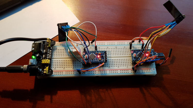
  • Many thanks for help - today I made it work 🙂 Here are my steps that worked for me:

    • I used MYSController 1.0.0 beta, took bootloader MYSBootloaderV13pre.hex and uploaded to Arduino Mini Pro with AVRDUDESS and USBasp programmer
    • then uploaded serial gateway sketch to another Mini Pro
    • attached nR24L01+ radios to both
    • connected MYSController, configured serial connection and all just started to work
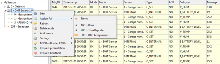
    • then uploaded simple DHT sketch, edited csv file in MYSController and selected it for OTA FW update

    After less than minute new FW was already at the node and it started to send data. I am very happy 🙂 I played with Arduino projects for several years, but this stuff you have made is absolutely amazing! Now time for some real nodes - first one will be stepper controller for telescope focuser.

    0_1501268069710_mysboot.jpg
    0_1501268078807_mysboot2.jpg


  • It still works fine - however I have one more question, maybe stupid 🙂 About RF channels. I use nR24L01+ radios at default channel 76, however for final solution I would like to switch to some higher freq. Does precompiled bootlader work only at this default channel 76? So if I would like to switch to channel 101 I need to compile bootloader with this setting? Or there is some magic behind that makes it work some other way?


  • Admin

    @jolo Glad to hear that 🙂 re RF24 channel: yes, you need to change and recompile the bootloader for different communication settings. See here: https://github.com/mysensors/MySensorsBootloaderRF24/blob/development/MYSBootloader.c#L45-L51


  • Really want to try FOTA with MYSBoatloader but a little bit confused. First - do i have to burn the fuses (i'm using a chinese arduino mini pro 16Mhz) or can simply download MYSBootloader_16MHz.hex from dev brach and i'm good to go?

    Another thing - i'm using an MQTT gateway attached to RPi3. Don't really want to change the gateway type - so is there a way to do OTA update? I have a spare UNO which i can connect to a notebook.


  • Mod

    It was mentioned in a previous thread that mycontroller can do fota also through mqtt


  • @gohan Excellent. Searched through the thread but couldn't find any mentions how it can be done via mqtt What about the fuses?


  • Mod

    Just try using mycontroller, the procedure should be the same as the ethernet gateway


  • Yes thank you for the tip! Mycontroller works.
    For Mini Pro - no fuses are needed. Just download the hex - rename and flash.
    What about the nano?
    Looking at boards.txt i see only two difeerences

    Nano
    nano.menu.cpu.atmega328.bootloader.low_fuses=0xFF
    nano.menu.cpu.atmega328.bootloader.extended_fuses=0xFD

    Mys
    proMYSBL.bootloader.low_fuses=0xF7
    proMYSBL.bootloader.extended_fuses=0x06

    But at the same time PRO mini is same as nano... So can also flash straight away?


  • Nano also doesn't need any fuses. So everything works. Except to begin the flash procedure i have to unplug and plug the node. Is this intended behaviour? Otherwise i only see in MQTT one line of code and no response from node


  • Mod

    Is the node doing any kind of sleep?


  • No it's powered off mains so no sleep functions added


  • Mod

    I think you have to issue a reboot node from the mycontroller or myscontroller to have the OTA start


  • @gohan So is it first reboot. Or start flashing - reboot?


  • Mod

    You assign firmware to upload to node and then you send a reboot, if I remember correctly


  • Plugin Developer

    @moskovskiy82 If you use MyController, Yes, you should assign the firmware for the node and send reboot.


  • @jkandasa Thank you!

    One more question. Now need to use a 3,3V arduino Pro (chinese version) (Nano and 5V version flashed via the uno without a hitch)

    This is what i put into boards.txt The MYSBootloader_8Mhz.hex is from the dev branch

    proMYSBL8.name=ATmega328 8Mhz MYSBootloader
    
    proMYSBL8.name=ATmega328 internal 8Mhz with MYSBootloader
    proMYSBL8.upload.tool=avrdude
    proMYSBL8.upload.protocol=arduino
    proMYSBL8.upload.maximum_size=30720
    proMYSBL8.upload.maximum_data_size=2048
    proMYSBL8.upload.speed=57600
    proMYSBL8.bootloader.tool=avrdude
    proMYSBL8.bootloader.low_fuses=0xE2
    proMYSBL8.bootloader.high_fuses=0xDA
    proMYSBL8.bootloader.extended_fuses=0x06
    proMYSBL8.bootloader.unlock_bits=0x3F
    proMYSBL8.bootloader.lock_bits=0xFF
    proMYSBL8.bootloader.file=MySensors/MYSBootloader_8Mhz.hex
    proMYSBL8.build.mcu=atmega328p
    proMYSBL8.build.f_cpu=8000000L
    proMYSBL8.build.board=AVR_UNO
    proMYSBL8.build.core=arduino
    proMYSBL8.build.variant=standard
    

    Tried to flash the mysbootloader but get the following error

    C:\Program Files (x86)\Arduino\hardware\tools\avr/bin/avrdude -CC:\Program Files (x86)\Arduino\hardware\tools\avr/etc/avrdude.conf -v -patmega328p -cstk500v1 -PCOM7 -b19200 -e -Ulock:w:0x3F:m -Uefuse:w:0x06:m -Uhfuse:w:0xDA:m -Ulfuse:w:0xE2:m 
    
    avrdude: Version 6.3, compiled on Jan 17 2017 at 12:00:53
             Copyright (c) 2000-2005 Brian Dean, http://www.bdmicro.com/
             Copyright (c) 2007-2014 Joerg Wunsch
    
             System wide configuration file is "C:\Program Files (x86)\Arduino\hardware\tools\avr/etc/avrdude.conf"
    
             Using Port                    : COM7
             Using Programmer              : stk500v1
             Overriding Baud Rate          : 19200
             AVR Part                      : ATmega328P
             Chip Erase delay              : 9000 us
             PAGEL                         : PD7
             BS2                           : PC2
             RESET disposition             : dedicated
             RETRY pulse                   : SCK
             serial program mode           : yes
             parallel program mode         : yes
             Timeout                       : 200
             StabDelay                     : 100
             CmdexeDelay                   : 25
             SyncLoops                     : 32
             ByteDelay                     : 0
             PollIndex                     : 3
             PollValue                     : 0x53
             Memory Detail                 :
    
                                      Block Poll               Page                       Polled
               Memory Type Mode Delay Size  Indx Paged  Size   Size #Pages MinW  MaxW   ReadBack
               ----------- ---- ----- ----- ---- ------ ------ ---- ------ ----- ----- ---------
               eeprom        65    20     4    0 no       1024    4      0  3600  3600 0xff 0xff
               flash         65     6   128    0 yes     32768  128    256  4500  4500 0xff 0xff
               lfuse          0     0     0    0 no          1    0      0  4500  4500 0x00 0x00
               hfuse          0     0     0    0 no          1    0      0  4500  4500 0x00 0x00
               efuse          0     0     0    0 no          1    0      0  4500  4500 0x00 0x00
               lock           0     0     0    0 no          1    0      0  4500  4500 0x00 0x00
               calibration    0     0     0    0 no          1    0      0     0     0 0x00 0x00
               signature      0     0     0    0 no          3    0      0     0     0 0x00 0x00
    
             Programmer Type : STK500
             Description     : Atmel STK500 Version 1.x firmware
             Hardware Version: 2
             Firmware Version: 1.18
             Topcard         : Unknown
             Vtarget         : 0.0 V
             Varef           : 0.0 V
             Oscillator      : Off
             SCK period      : 0.1 us
    
    avrdude: AVR device initialized and ready to accept instructions
    
    Reading | ################################################## | 100% 0.03s
    
    avrdude: Device signature = 0x1e950f (probably m328p)
    avrdude: erasing chip
    avrdude: reading input file "0x3F"
    avrdude: writing lock (1 bytes):
    
    Writing | ################################################## | 100% 0.01s
    
    avrdude: 1 bytes of lock written
    avrdude: verifying lock memory against 0x3F:
    avrdude: load data lock data from input file 0x3F:
    avrdude: input file 0x3F contains 1 bytes
    avrdude: reading on-chip lock data:
    
    Reading | ################################################## | 100% 0.01s
    
    avrdude: verifying ...
    avrdude: 1 bytes of lock verified
    avrdude: reading input file "0x06"
    avrdude: writing efuse (1 bytes):
    
    Writing |  ***failed;  
    ################################################## | 100% 0.07s
    
    avrdude: 1 bytes of efuse written
    avrdude: verifying efuse memory against 0x06:
    avrdude: load data efuse data from input file 0x06:
    avrdude: input file 0x06 contains 1 bytes
    avrdude: reading on-chip efuse data:
    
    Reading | ################################################## | 100% 0.01s
    
    avrdude: verifying ...
    avrdude: WARNING: invalid value for unused bits in fuse "efuse", should be set to 1 according to datasheet
    This behaviour is deprecated and will result in an error in future version
    You probably want to use 0xfe instead of 0x06 (double check with your datasheet first).
    avrdude: 1 bytes of efuse verified
    avrdude: reading input file "0xDA"
    avrdude: writing hfuse (1 bytes):
    
    Writing | ################################################## | 100% 0.01s
    
    avrdude: 1 bytes of hfuse written
    avrdude: verifying hfuse memory against 0xDA:
    avrdude: load data hfuse data from input file 0xDA:
    avrdude: input file 0xDA contains 1 bytes
    avrdude: reading on-chip hfuse data:
    
    C:\Program Files (x86)\Arduino\hardware\tools\avr/bin/avrdude -CC:\Program Files (x86)\Arduino\hardware\tools\avr/etc/avrdude.conf -v -patmega328p -cstk500v1 -PCOM7 -b19200 -Uflash:w:C:\Program Files (x86)\Arduino\hardware\arduino\avr/bootloaders/MySensors/MYSBootloader_8Mhz.hex:i -Ulock:w:0xFF:m 
    
    avrdude: Version 6.3, compiled on Jan 17 2017 at 12:00:53
    Reading | ################################################## | 100% 0.01s
             Copyright (c) 2000-2005 Brian Dean, http://www.bdmicro.com/
    
             Copyright (c) 2007-2014 Joerg Wunsch
    avrdude: verifying ...
    
    avrdude: 1 bytes of hfuse verified
             System wide configuration file is "C:\Program Files (x86)\Arduino\hardware\tools\avr/etc/avrdude.conf"
    avrdude: reading input file "0xE2"
    avrdude: writing lfuse (1 bytes):
    
    Writing | ################################################## | 100% 0.01s
    
    avrdude: 1 bytes of lfuse written
    avrdude: verifying lfuse memory against 0xE2:
    avrdude: load data lfuse data from input file 0xE2:
    avrdude: input file 0xE2 contains 1 bytes
    avrdude: reading on-chip lfuse data:
    
    Reading | ################################################## | 100% 0.01s
    
    avrdude: verifying ...
    avrdude: 1 bytes of lfuse verified
    
    avrdude done.  Thank you.
    
    
             Using Port                    : COM7
             Using Programmer              : stk500v1
             Overriding Baud Rate          : 19200
             AVR Part                      : ATmega328P
             Chip Erase delay              : 9000 us
             PAGEL                         : PD7
             BS2                           : PC2
             RESET disposition             : dedicated
             RETRY pulse                   : SCK
             serial program mode           : yes
             parallel program mode         : yes
             Timeout                       : 200
             StabDelay                     : 100
             CmdexeDelay                   : 25
             SyncLoops                     : 32
             ByteDelay                     : 0
             PollIndex                     : 3
             PollValue                     : 0x53
             Memory Detail                 :
    
                                      Block Poll               Page                       Polled
               Memory Type Mode Delay Size  Indx Paged  Size   Size #Pages MinW  MaxW   ReadBack
               ----------- ---- ----- ----- ---- ------ ------ ---- ------ ----- ----- ---------
               eeprom        65    20     4    0 no       1024    4      0  3600  3600 0xff 0xff
               flash         65     6   128    0 yes     32768  128    256  4500  4500 0xff 0xff
               lfuse          0     0     0    0 no          1    0      0  4500  4500 0x00 0x00
               hfuse          0     0     0    0 no          1    0      0  4500  4500 0x00 0x00
               efuse          0     0     0    0 no          1    0      0  4500  4500 0x00 0x00
               lock           0     0     0    0 no          1    0      0  4500  4500 0x00 0x00
               calibration    0     0     0    0 no          1    0      0     0     0 0x00 0x00
               signature      0     0     0    0 no          3    0      0     0     0 0x00 0x00
    
             Programmer Type : STK500
             Description     : Atmel STK500 Version 1.x firmware
             Hardware Version: 2
             Firmware Version: 1.18
             Topcard         : Unknown
             Vtarget         : 0.0 V
             Varef           : 0.0 V
             Oscillator      : Off
             SCK period      : 0.1 us
    
    avrdude: AVR device initialized and ready to accept instructions
    
    Reading | ################################################## | 100% 0.02s
    
    avrdude: Device signature = 0x1e950f (probably m328p)
    avrdude: NOTE: "flash" memory has been specified, an erase cycle will be performed
             To disable this feature, specify the -D option.
    avrdude: erasing chip
    avrdude: reading input file "C:\Program Files (x86)\Arduino\hardware\arduino\avr/bootloaders/MySensors/MYSBootloader_8Mhz.hex"
    avrdude: writing flash (32754 bytes):
    
    Writing | ################################################## | 100% 0.00s
    
    avrdude: 32754 bytes of flash written
    avrdude: verifying flash memory against C:\Program Files (x86)\Arduino\hardware\arduino\avr/bootloaders/MySensors/MYSBootloader_8Mhz.hex:
    avrdude: load data flash data from input file C:\Program Files (x86)\Arduino\hardware\arduino\avr/bootloaders/MySensors/MYSBootloader_8Mhz.hex:
    avrdude: input file C:\Program Files (x86)\Arduino\hardware\arduino\avr/bootloaders/MySensors/MYSBootloader_8Mhz.hex contains 32754 bytes
    avrdude: reading on-chip flash data:
    
    Reading | ################################################## | 100% 0.00s
    
    avrdude: verifying ...
    avrdude: verification error, first mismatch at byte 0x7800
             0x00 != 0x11
    avrdude: verification error; content mismatch
    
    avrdude done.  Thank you.
    
    Error while burning bootloader.


  • @moskovskiy82 My boards.txt specify bootloader.low_fuses=0xF7 as the Arduino being programmed has a crystal on board.

    One other thing: I built my own programming board, to support programming ATMega 328p chips and Pro boards in 3.3v@8MHz and 5v@16Mhz... I used a switch and a level converter board to connect the Uno ICSP port to the pins of the Pro.

    Uno pins are 5V output, they would burn the input pins of the 3.3v Pro chip, did you account for that ?


  • Mod

    You can use 5v to program a 3.3v pro mini as the chip is the same, one is only clocked down to 8Mhz in order to be stable at 3.3v


  • @gohan I beg to differ. On Page 299 of Atmel's ATMega 328p datasheet you can verify that the Absolute Maximum Ratings table states : "Voltage on any Pin except RESET with respect to Ground . . . . . . . . . .-0.5V to VCC+0.5V" which adds to 3.8V for a 3.3V Pro.

    And also: *NOTICE: Stresses beyond those listed under “Absolute Maximum Ratings” may cause permanent damage to the device.

    Perhaps you have mistaken the Pro for the NRF24L01+ radio which is supplied by 3.3v but has 5Volt tolerant inputs ?

    Otherwise there would be no need for those USB to FTDI boards with 3v3/5V selection jumpers ...


  • Mod

    I programmed the pro mini with 5v and it worked. Maybe I was lucky. The 3v ftdi adapter is mandatory for esp8266 for example.


  • @tekka for OSX, the sequencing of flags matters. So, line 45 can be:

    $(PROJECT).o: $(PROJECT).c
    "$(BINPATH)avr-gcc" $(CFLAGS) -I$(INCLUDES) $< -o $@
    

    can be improved to

    $(PROJECT).o: $(PROJECT).c
    "$(BINPATH)avr-gcc" -I$(INCLUDES) $(CFLAGS) $< -o $@
    

    and it all works.

    Also, if anyone is getting error for "avr-gcc" not found, then just add the path to avr-gcc in your path.


  • Admin

    @Bhavin-Doshi Thanks for reporting - could you prepare a PR?
    https://github.com/mysensors/MySensorsBootloaderRF24


  • Admin

    @Bhavin-Doshi PR merged. Thank you!


  • @tekka, I am planning to move from MySensors v2.0.0 to v2.1.1, do I need to use the updated MYSBootloader? Currently I am using MYSBootloader 1.3 pre-relase (https://forum.mysensors.org/topic/3453/mysbootloader-1-3-pre-release-myscontroller-1-0-0beta).

    Can you please also help me understand the differences in the low_fuses and high_fuses values in the older version of bootloader and the latest version?


  • Admin

    @nagurao.basude no, you don't need to but the new version has some stability improvements. The fuse differences are to better match HW (osc type) & clearing eeprom.

    AVR fuse calculator: http://www.engbedded.com/fusecalc/


  • Hardware Contributor

    Hello, has someone used the 1MHz precompiled bootloader ? If yes what baud rate did you use to communicate via serial ?
    I flashed it on a node but I can't upload any script ("not in sync" error). If I believe HW.h it should be 9600 bauds but I have tried hat and nearly every baudrate with no luck.
    I had no problem using the 8MHz version.

    The only way I could use the 1MHz bootloader at the moment is to flash the hex file containing both bootloader and script.
    Sorry to ask this stupid question, I wanted to compile the bootloader but Internet connection is nearly down and I can't even download Atmel Studio 😞


  • @tekka Thank you very much for the response. I will just start migrating my existing nodes to MySensors v2.1.1library.


  • @tekka try as I might, I can't get the nodes to respond to the new 'signal report' option in MYS Controller, any ideas why?


  • Admin

    @Mark-Swift This feature only works on MySensors >=2.2.0


  • @tekka said in MYSBootloader 1.3.0-beta.3:

    @Mark-Swift This feature only works on MySensors >=2.2.0

    @tekka I'm using the latest dev branch on all my nodes and gateway...


  • Admin

    @Mark-Swift Hmm, that's odd - just tested it here with the latest dev and all is ok. Can you post the logs + node sketch?


  • Hello,

    I have notice strange behavior with MYSBootloaderV13pre.hex 8MHz internal bootloader.

    Problem: When I burn MYSBootloaderV13pre.hex 8MHz internal bootloader to my Standalone Atmega328p i testing it with Arduino Blink and Fade sketches. Problem is that theese sketches doesn't work on this bootloader. LED is just always ON.

    I also tested the same sketches, same wiring, same Arduino Uno (5V when programming), same FTDI programmer (3.3V), same PC with Win 10 with same drivers, same Atmega328p with Nick Gammon Atmega Board Programmer when I burn Lilypad bootloader and then upload Blink and Fade sketches, they perfectly working.

    I tried same uploading with Arduino IDE 1.6.5 and also with the newest version 1.8.5.
    As a programmer I using Arduino as ISP. I theese tests when burning bootloader I don't connect external oscilator.

    With Nick Gammon software I also checked fuses for both Lilypad and MYSBootloader settings, becose i was thought it is becose of them. Once I configure wrong fuses and it had a lot of time to reset it to default value.
    Question: So now before changing fuses I want to ask maybe someone have been faced with similar problem?

    I paste below info about Lilipad and MYSBootloader 8MHz internal oscilator boards fuse settings:

    Lilypad bootloader
    
    Atmega fuse calculator.
    Written by Nick Gammon.
    Version 1.11
    Compiled on Nov 30 2017 at 17:36:58 with Arduino IDE 10805.
    Attempting to enter programming mode ...
    Entered programming mode OK.
    Signature = 0x1E 0x95 0x0F 
    Processor = ATmega328P
    Flash memory size = 32768
    LFuse = 0xE2 
    HFuse = 0xDA 
    EFuse = 0xFD 
    Lock byte = 0xEF 
    Clock calibration = 0x8E 
    External Reset Disable.................. [ ]
    Debug Wire Enable....................... [ ]
    Enable Serial (ICSP) Programming........ [X]
    Watchdog Timer Always On................ [ ]
    Preserve EEPROM through chip erase...... [ ]
    Boot into bootloader.................... [X]
    Divide clock by 8....................... [ ]
    Clock output............................ [ ]
    Bootloader size: 2048 bytes.
    Start-up time: SUT0: [X]  SUT1: [ ] (see datasheet)
    Clock source: calibrated internal oscillator.
    Brownout detection at: 2.7V.
    
    MYSBootloaderV13pre bootloader
    
    Atmega fuse calculator.
    Written by Nick Gammon.
    Version 1.11
    Compiled on Nov 30 2017 at 19:48:16 with Arduino IDE 10805.
    Attempting to enter programming mode ...
    Entered programming mode OK.
    Signature = 0x1E 0x95 0x0F 
    Processor = ATmega328P
    Flash memory size = 32768
    LFuse = 0xE2 
    HFuse = 0xD2 
    EFuse = 0xFE 
    Lock byte = 0xFF 
    Clock calibration = 0x8E 
    External Reset Disable.................. [ ]
    Debug Wire Enable....................... [ ]
    Enable Serial (ICSP) Programming........ [X]
    Watchdog Timer Always On................ [ ]
    Preserve EEPROM through chip erase...... [X]
    Boot into bootloader.................... [X]
    Divide clock by 8....................... [ ]
    Clock output............................ [ ]
    Bootloader size: 2048 bytes.
    Start-up time: SUT0: [X]  SUT1: [ ] (see datasheet)
    Clock source: calibrated internal oscillator.
    Brownout detection at: 1.8V.
    

    I appreciate any helpful info!

    EDIT: I think I already found that there is newer MYSBootloader files of development version which working without problems. I will test it if I write good fuses 🙂


  • @tekka said in MYSBootloader 1.3.0-beta.3:

    @Mark-Swift Hmm, that's odd - just tested it here with the latest dev and all is ok. Can you post the logs + node sketch?

    @tekka, just tried again, perhaps I'm missing something obvious?

    I have the gateway and node using the latest dev branch, I click the node in MYS and then request a signal report - I see a tx in the log but nothing further? Do I need anything in the node sketch or the gateway? Does this work with the NRF's?


  • Admin

    @tekka said in MYSBootloader 1.3.0-beta.3:

    @Mark-Swift Hmm, that's odd - just tested it here with the latest dev and all is ok. Can you post the logs + node sketch?


  • Hello,

    Q1: Does anybody was able to succesfully use 8MHz MYSBootloader 1.3.0-beta.3 on standalone Atmega328p?

    All bootloaders I testing with Arduino BLINK example.
    Arduino 1.8.5

    I was testing 8MHz internal oscilator MYSBootloader 1.3.0-beta.3 with fuses on 2 different Atmega328p standalone but I can't upload sketch to it and test it. Arduino avrdude says that:
    avrdude: stk500_recv(): programmer is not responding
    avrdude: stk500_getsync() attempt 1 of 10: not in sync: resp=0x4a

    Used fuses:
    proMYSBL8.bootloader.low_fuses=0xE2
    proMYSBL8.bootloader.high_fuses=0xDA
    proMYSBL8.bootloader.extended_fuses=0x06 / 07
    proMYSBL8.bootloader.unlock_bits=0x3F
    proMYSBL8.bootloader.lock_bits=0x3F / 0F

    Before that, I was burned my Atmega328p with 1MHz internal oscilator MYSBootloader 1.3.0-beta.3 bootloader and it was working.

    Also I was testing 8MHz internal oscilator MYSBootloader 1.3pre2 with fuses on 2 different Atmega328p standalone and I can upload sketch to it and test it.
    Used fuses:
    proMYSBL8.bootloader.low_fuses=0xE2
    proMYSBL8.bootloader.high_fuses=0xDA
    proMYSBL8.bootloader.extended_fuses=0x06 / 07
    proMYSBL8.bootloader.unlock_bits=0x3F
    proMYSBL8.bootloader.lock_bits=0x3F / 0F

    Q2: I noticed that with 8MHz internal oscilator MYSBootloader 1.3pre2 LED blinks not continuosly it like (* led ON; - led OFF):
    *** --- *** --- *** --- ** - * - * - * - [cycle ends, then repeats again] *** --- *** --- *** --- ** - * - * - * - ...
    And this one cycle of *** --- *** --- *** --- ** - * - * - * - takes ~8 seconds. Could it be something with watchdog timer? I not very know about this setting.

    Thank You for help!


  • Admin

    @Mark-Swift said in MYSBootloader 1.3.0-beta.3:

    @tekka said in MYSBootloader 1.3.0-beta.3:

    @Mark-Swift Hmm, that's odd - just tested it here with the latest dev and all is ok. Can you post the logs + node sketch?

    @tekka, just tried again, perhaps I'm missing something obvious?

    I have the gateway and node using the latest dev branch, I click the node in MYS and then request a signal report - I see a tx in the log but nothing further? Do I need anything in the node sketch or the gateway? Does this work with the NRF's?

    Did you try with 1.3.0-beta.4? https://github.com/mysensors/MySensorsBootloaderRF24/tree/development


  • @tekka said in MYSBootloader 1.3.0-beta.3:

    @Mark-Swift said in MYSBootloader 1.3.0-beta.3:

    @tekka said in MYSBootloader 1.3.0-beta.3:

    @Mark-Swift Hmm, that's odd - just tested it here with the latest dev and all is ok. Can you post the logs + node sketch?

    @tekka, just tried again, perhaps I'm missing something obvious?

    I have the gateway and node using the latest dev branch, I click the node in MYS and then request a signal report - I see a tx in the log but nothing further? Do I need anything in the node sketch or the gateway? Does this work with the NRF's?

    Did you try with 1.3.0-beta.4? https://github.com/mysensors/MySensorsBootloaderRF24/tree/development

    @tekka that did it, it's now working... now to figure out what the returned signal report numbers mean 🙂


  • @tekka thank You for the answer. I'm not sure is answer was dedicated for me or for Mark, but I tested 1.3.0-beta.4 in the same way I described before:

    • Tested with 2 different Atmega328p
    • First try was with 1MHz - working on both Atmega328p
    • Second try with 8MHz - same situation as with beta 3, skecth won't upload and I get answer from Arduino Avrdude (this time I post full log after uploading):
    avrdude: Version 6.3, compiled on Jan 17 2017 at 12:00:53
             Copyright (c) 2000-2005 Brian Dean, http://www.bdmicro.com/
             Copyright (c) 2007-2014 Joerg Wunsch
    
             System wide configuration file is "C:\Program Files (x86)\Arduino\hardware\tools\avr/etc/avrdude.conf"
    
             Using Port                    : COM4
             Using Programmer              : arduino
             Overriding Baud Rate          : 38400
    avrdude: stk500_recv(): programmer is not responding
    avrdude: stk500_getsync() attempt 1 of 10: not in sync: resp=0xf1
    avrdude: stk500_recv(): programmer is not responding
    < ... >
    avrdude: stk500_recv(): programmer is not responding
    avrdude: stk500_getsync() attempt 10 of 10: not in sync: resp=0xf1
    
    avrdude done.  Thank you.
    

    It would be best if someone also could try to burn same bootloader on standalone Atmega328p and post results to be sure all wiring and steps I did is without mistakes.
    Strange if I I burn 1.3pre2 8MHz bootloader - it works.

    What troubleshooting I could make?


  • @tekka, Thanks for the link to the beta.4. bootloader. I have tried burning nodes using these and tested them by uploading the FW using MySController 1.0beta_b3316 (latest update meant for MySensors2.2.0) with SerialGatewaySketches using both MySensors2.2.0_rc1 and MySensrs2.2.0_pre1 libraries.

    MysController doesn't seem to even recognize the Beta.4 bootloaded Nodes (Promini 5V16Mhz with default provided fuse settings from Makefile). The extra nRF chip wiring checks and precautions (0.01uF and 100uF Caps) have been taken. What might be the problem? How to debug when SerialMontitor cant be used? Any Network Sniffer link if that helps...

    I guess the MySensors library version of the SerialGateway sketch may be posing a problem. Can you please help me with a link of the correct MySensors library version to use with beta.4 bootloaded nodes?

    Any help will be appreciated...


  • Hi @tekka!
    Do you plan to add support for the RFM69 module in MYSBootloader?


  • No help from the community! Sad!!!


  • Admin

    @wanvo This would certainly be a great addition to MYSBootloader - but very limited dev time atm. Community contributions on that topic are welcome 😉


  • Admin

    @vikasjee Apologies for the late reply - I have no idea what's the issue with your setup - my guess is that something is wrong with the fuses and/or wrong .hex used: Can you post the MYSController log, used fuse settings and any other important information?


  • @tekka thanks for the answer. I'm still a newbie.
    Now I can not make a contribution to the development due to my incompetence.
    I can help as a tester 🙂


  • @jacikaas

    Hello, maybe someone was trying 8MHz bootloader for standlaone Atmega328p?


  • Hi,

    Anyone seen this error on latest 1.3 release? It seems a define is not done for F_CPU, what am I missing here?

    Generating function prototypes...
    In file included from C:\Program Files (x86)\Arduino\portable\sketchbook\libraries\MySensors/MySensors.h:371:0,
    
    from C:\Program Files (x86)\Arduino\portable\sketchbook\libraries\MySensors\examples\GatewayW5100MQTTClient\GatewayW5100MQTTClient.ino:138:
    
    C:\Program Files (x86)\Arduino\portable\sketchbook\libraries\MySensors/core/MyTransport.cpp:777:42: error: operator '>' has no left operand
    
     #if defined(MY_GATEWAY_FEATURE) && (F_CPU>16000000)
    
                                              ^
    
    In file included from C:\Program Files (x86)\Arduino\portable\sketchbook\libraries\MySensors/MySensors.h:396:0,
    
                     from C:\Program Files (x86)\Arduino\portable\sketchbook\libraries\MySensors\examples\GatewayW5100MQTTClient\GatewayW5100MQTTClient.ino:138:
    
    C:\Program Files (x86)\Arduino\portable\sketchbook\libraries\MySensors/core/MySensorsCore.cpp:479:11: error: operator '>' has no left operand
    
     #if (F_CPU>16000000)
    
               ^
    exit status 1
    Error compiling for board ATmega328 with MYSBootloader 1.3.0.
    

    Regards


  • @cdr Same Problem here!

    Greetz Henry


  • @cdr @Henry I ran into the same issue. Turned out to be a syntax issue in the boards.txt file. If you change:

    MYSBL.menu.frequency.MYSBL16.f_cpu=16000000L
    

    into

    MYSBL.menu.frequency.MYSBL16.build.f_cpu=16000000L
    

    Then it works again. Adding build. needs to be done for the other menu entries as well.


Log in to reply
 

Suggested Topics

  • 1
  • 2
  • 2
  • 1
  • 5
  • 3

0
Online

11.2k
Users

11.1k
Topics

112.5k
Posts