nRF5 action!
-
@Jokgi said in nRF5 Bluetooth action!:
you must be powering your target boards with 3vdc to 3.3vdc. (I have tested down to 2.8vdc but it is not guaranteed to work consistently.) Not sure about ST or other programmers.
Thanks for reminding me of this. It turns out to be true for the J-Link programmers which are for sale on Aliexpress.com as well.
@NeverDie I am not sure about all the boards for sell on that site. but I would have to say that any J-link programmer that is packaged as such for $12-$40 dollars is probably counterfeit. Updating these items with newer J-link firmware would more then likely disable them. (On purpose) You may wish to contact Segger in Boston prior to spending money on these potential clones. I would be interested to hear what experiences other people have had with the products from that site.
The genuine J-link and j-link plus programmers are over $400.00 as you can see on the Digi-Key website. Per the Segger license agreements, the only J-link 0B devices that are able to be sold are to be bundled with a Evaluation / Development kit such as the nRF52-DK, ST, Rigato, and other semiconductor / module manufacture's dev kits.
-
@NeverDie I am not sure about all the boards for sell on that site. but I would have to say that any J-link programmer that is packaged as such for $12-$40 dollars is probably counterfeit. Updating these items with newer J-link firmware would more then likely disable them. (On purpose) You may wish to contact Segger in Boston prior to spending money on these potential clones. I would be interested to hear what experiences other people have had with the products from that site.
The genuine J-link and j-link plus programmers are over $400.00 as you can see on the Digi-Key website. Per the Segger license agreements, the only J-link 0B devices that are able to be sold are to be bundled with a Evaluation / Development kit such as the nRF52-DK, ST, Rigato, and other semiconductor / module manufacture's dev kits.
@Jokgi said in nRF5 Bluetooth action!:
@NeverDie I am not sure about all the boards for sell on that site. but I would have to say that any J-link programmer that is packaged as such for $12-$40 dollars is probably counterfeit. Updating these items with newer J-link firmware would more then likely disable them. (On purpose) You may wish to contact Segger in Boston prior to spending money on these potential clones. I would be interested to hear what experiences other people have had with the products from that site.
The genuine J-link and j-link plus programmers are over $400.00 as you can see on the Digi-Key website. Per the Segger license agreements, the only J-link 0B devices that are able to be sold are to be bundled with a Evaluation / Development kit such as the nRF52-DK, ST, Rigato, and other semiconductor / module manufacture's dev kits.
When would I need to upgrade the firmware? At least for now it seems to work just fine.
-
@NeverDie I am not sure about all the boards for sell on that site. but I would have to say that any J-link programmer that is packaged as such for $12-$40 dollars is probably counterfeit. Updating these items with newer J-link firmware would more then likely disable them. (On purpose) You may wish to contact Segger in Boston prior to spending money on these potential clones. I would be interested to hear what experiences other people have had with the products from that site.
The genuine J-link and j-link plus programmers are over $400.00 as you can see on the Digi-Key website. Per the Segger license agreements, the only J-link 0B devices that are able to be sold are to be bundled with a Evaluation / Development kit such as the nRF52-DK, ST, Rigato, and other semiconductor / module manufacture's dev kits.
@Jokgi said in nRF5 Bluetooth action!:
@NeverDie I am not sure about all the boards for sell on that site. but I would have to say that any J-link programmer that is packaged as such for $12-$40 dollars is probably counterfeit. Updating these items with newer J-link firmware would more then likely disable them. (On purpose)
Yes they are of course counterfeit, and using old firmware. You have a message when you use them with Segger software asking you to upgrade to newer firmware and if you accept your programmer is disabled (web is full of solutions to reflash a firmware).
But if you don't upgrade the firmware it works fine as a SWD programmer, at least for basic use (programming). I have not tried any debugging. -
Are we limited to using RTC0? I've tried switching to RTC1 and RTC2, and I get the sense there are conflicts with both of them and the MySensors code if they're used.
@NeverDie said in nRF5 Bluetooth action!:
Are we limited to using RTC0? I've tried switching to RTC1 and RTC2, and I get the sense there are conflicts with both of them and the MySensors code if they're used.
RTC1 is blocked by arduino (nRF5/delay.c) and RTC0 (nRF51) and RTC2 (nRF52) is used in MySensors (hal/architecture/MyHwNRF5.cpp)
-
Success. I now have a "listen mode" for the nRF52832 radio that's completely controlled by the PPI while the MCU sleeps. Presently, it wakes up the radio every 100ms and listens for 1ms. This means no wasted power from oversight by the MCU. Using just the PPI, I can control to within about 30us over how long to make the cycle period and/or the listening duration.
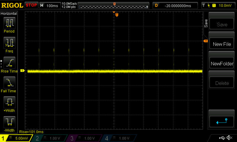
The scope shots show the current drawn. Scale: 1mv=1ma. As you can see, the DCDC regulator is engaged.
Next step will be to have packet receipt wake up the MCU via an ISR, so that the packet can be processed. After that, I'll see how narrow I can make the receive window and still receive packets reliably. I think under 100us will be possible. Maybe even less than 60us if the bitrate is 2mbps. :)
-
Success. I now have a "listen mode" for the nRF52832 radio that's completely controlled by the PPI while the MCU sleeps. Presently, it wakes up the radio every 100ms and listens for 1ms. This means no wasted power from oversight by the MCU. Using just the PPI, I can control to within about 30us over how long to make the cycle period and/or the listening duration.
The scope shots show the current drawn. Scale: 1mv=1ma. As you can see, the DCDC regulator is engaged.
Next step will be to have packet receipt wake up the MCU via an ISR, so that the packet can be processed. After that, I'll see how narrow I can make the receive window and still receive packets reliably. I think under 100us will be possible. Maybe even less than 60us if the bitrate is 2mbps. :)
@NeverDie Great Job!!!! Suggestion... If you are going to use the BTLE Softdevice you will have a smaller receive window if you use the external 32khz crystal option rather then the internal 32khz RC one. (+/- 20ppm with the crystal vs +/- 250 or 500ppm with the RC.
-
At the extreme, one of the questions that will need answering is: what's the minimum number of bytes in a transmitted frame that you really do need before the receiver starts receiving garbage packets? For instance, a 10 byte frame, which should be more than adequate, would take 40us of airtime to either transmit or receive at 2mbps bitrate. One could get to a lower number by maybe sending a null packet as a wake-up packet, in which case maybe you also don't need CRC. So, that leaves you with some preamble, a network ID, and maybe a destination ID--or about 5 bytes. So, that would be around 20us of airtime. One could shrink that further by reducing the number of network ID bytes, but too much of that and possibly one starts to receive garbage packets.
The RFM69 doesn't try to decode packets whose RSSI is below a specific programmable threshhold. I don't believe the nRF52 radio uses RSSI as a filter in that way though. It seems that the nRF52832 radio tries to decode whatever it's receiving, regardless of the RSSI. Or, at least, that's how I remember it. Anyone else played around with it?
-
I adapted your RTC0 code for handling IRQ's, and it looks like this:
NRF_RADIO->INTENSET = B100; //interrupt MCU if a payload is received. // Enable interrupt NVIC_SetPriority(RADIO_IRQn, 15); NVIC_ClearPendingIRQ(RADIO_IRQn); NVIC_EnableIRQ(RADIO_IRQn); #if __CORTEX_M == 0x04 #define NRF5_RESET_EVENT(event) \ event = 0; \ (void)event #else #define NRF5_RESET_EVENT(event) event = 0 #endif // This must be in one line extern "C" { void RADIO_IRQHandler(void) {packetCounter++; NRF5_RESET_EVENT(NRF_RADIO->EVENTS_PAYLOAD); NRF_RADIO->EVENTS_PAYLOAD=0; }}Question: Is
NRF5_RESET_EVENT(NRF_RADIO->EVENTS_PAYLOAD);doing anything more than
NRF_RADIO->EVENTS_PAYLOAD=0;is?
-
The good news is that I can now literally "see" that the listen-mode is receiving packets, because I've programmed the PPI to toggle an LED every time a packet is received (and it only toggles the LED if and only if I know that I'm sending the node packets from a different node). The bad news is that--so far, anyway--it doesn't appear to trigger an IRQ event that wakes up the MCU and runs the ISR.
-
At the extreme, one of the questions that will need answering is: what's the minimum number of bytes in a transmitted frame that you really do need before the receiver starts receiving garbage packets? For instance, a 10 byte frame, which should be more than adequate, would take 40us of airtime to either transmit or receive at 2mbps bitrate. One could get to a lower number by maybe sending a null packet as a wake-up packet, in which case maybe you also don't need CRC. So, that leaves you with some preamble, a network ID, and maybe a destination ID--or about 5 bytes. So, that would be around 20us of airtime. One could shrink that further by reducing the number of network ID bytes, but too much of that and possibly one starts to receive garbage packets.
The RFM69 doesn't try to decode packets whose RSSI is below a specific programmable threshhold. I don't believe the nRF52 radio uses RSSI as a filter in that way though. It seems that the nRF52832 radio tries to decode whatever it's receiving, regardless of the RSSI. Or, at least, that's how I remember it. Anyone else played around with it?
-
It turns out that using just the standard radiohead packet/frame structure, I'm able to 100% reliably receive a two byte string (in this case, the letter "H" followed by a zero as the termination character) using the above PPI solution with a receive window of about 200ms. That includes preamble, CRC, and a long network ID number.
I'm pleased with that result. It's vastly better than without the PPI solution.
-
OK, I'm going to start with this, which works:
//A simplified re-mix of code mostly written by d00616

#include <nrf.h>
#include <MySensors.h>

int interrupt = 0;
uint32_t theCounter;


int8_t myHwSleep(unsigned long ms)
{
  hwSleepPrepare(ms);
  //while (nrf5_rtc_event_triggered == false) {
    hwSleep();
  //}
  hwSleepEnd(ms);
  return MY_WAKE_UP_BY_TIMER;
}


void setup() {
  // put your setup code here, to run once:
  Serial.begin(250000);
  Serial.println("Start");

  // Configure RTC
  NRF_RTC0->TASKS_STOP = 1;
  NRF_RTC0->PRESCALER = 32;
  NRF_RTC0->CC[0] = NRF_RTC0->COUNTER + (655);  //comparison for when to turn off the Rx.
  NRF_RTC0->EVTENSET = RTC_EVTENSET_COMPARE0_Msk;
  NRF_RTC0->INTENSET = RTC_INTENSET_COMPARE0_Msk;
  NRF_RTC0->TASKS_START = 1;
  NRF_RTC0->EVENTS_COMPARE[0] = 0;

  // Enable interrupt
  NVIC_SetPriority(RTC0_IRQn, 15);
  NVIC_ClearPendingIRQ(RTC0_IRQn);
  NVIC_EnableIRQ(RTC0_IRQn);
  Serial.println();
  Serial.println();
  Serial.println("Starting...");
}


void loop() {

  Serial.print(millis());
  Serial.print(" ");
  Serial.print(theCounter);
  Serial.print(" ");
  Serial.println(interrupt);
  myHwSleep(5000000);
}

/**
 * Reset events and read back on nRF52
 * http://infocenter.nordicsemi.com/pdf/nRF52_Series_Migration_v1.0.pdf
 */
#if __CORTEX_M == 0x04
#define NRF5_RESET_EVENT(event)                                                 \
        event = 0;                                                                   \
        (void)event
#else
#define NRF5_RESET_EVENT(event) event = 0
#endif

// This must be in one line
extern "C" { void RTC0_IRQHandler(void) {   theCounter=NRF_RTC0->COUNTER; NRF5_RESET_EVENT(NRF_RTC0->EVENTS_COMPARE[0]); interrupt++; NRF_RTC0->TASKS_CLEAR = 1; }}
and see if I can generate equivalent code which triggers on a pin change instead of an RTC event. If I can get that to work, then I'll take another stab at getting it to work based on the radio receiving a packet.
-
I was only partially done with the code, but I decided to run it anyway. Oddly enough, even though there is no reference to " RTC0_IRQHandler(void)" as being the event handler, it gets fired off anyway whenever I press the button (pin P0.16):
#include <nrf.h>
#include <MySensors.h>

int interrupt = 0;
uint32_t theCounter;


int8_t myHwSleep(unsigned long ms)
{
  hwSleepPrepare(ms);
   hwSleep();
  hwSleepEnd(ms);
  return MY_WAKE_UP_BY_TIMER;
}


void setup() {
  // put your setup code here, to run once:
  Serial.begin(250000);
  Serial.println("Start");

  //Configure GPIOTE
  NRF_GPIOTE->CONFIG[0]=0x31001;  // Toggle Event; Pin P0.16; Event Mode
                                  //So, any pin change on P0.16 will trigger an event.
                                   //On the Nordic nRF52 DK, Pin 0.16 is a button.

  NRF_GPIOTE->CONFIG[1]=0x131203;  //Initial setting: HIGH; Toggle Task; Pin P0.18; Task Mode
                                   //On the Nordic nRF52 DK, Pin 0.18 is an LED.
                                   //Note: initial setting of HIGH means that the LED will be initially OFF.

  NRF_GPIOTE->INTENSET=1;  //Enable an event on Pin P0.16 to trigger an interrupt.

  NRF_PPI->CH[0].EEP = (uint32_t)&NRF_GPIOTE->EVENTS_IN[0];  //P0.16 pin change occured.
  NRF_PPI->CH[0].TEP = (uint32_t)&NRF_GPIOTE->TASKS_OUT[1]; //Toggle LED on pin P0.18.

  NRF_PPI->CHENSET=B1; //enable Channel 0.

  // Enable interrupt
  NVIC_SetPriority(GPIOTE_IRQn, 15);
  NVIC_ClearPendingIRQ(GPIOTE_IRQn);
  NVIC_EnableIRQ(GPIOTE_IRQn);
  Serial.println();
  Serial.println();
  Serial.println("Starting...");
}


void loop() {

  Serial.print(millis());
  Serial.print(" ");
  Serial.print(theCounter);
  Serial.print(" ");
  Serial.println(interrupt);
  myHwSleep(5000000);
}

/**
 * Reset events and read back on nRF52
 * http://infocenter.nordicsemi.com/pdf/nRF52_Series_Migration_v1.0.pdf
 */
#if __CORTEX_M == 0x04
#define NRF5_RESET_EVENT(event)                                                 \
        event = 0;                                                                   \
        (void)event
#else
#define NRF5_RESET_EVENT(event) event = 0
#endif

// This must be in one line
extern "C" { void RTC0_IRQHandler(void) {   theCounter=NRF_RTC0->COUNTER; NRF5_RESET_EVENT(NRF_RTC0->EVENTS_COMPARE[0]); interrupt++; NRF_RTC0->TASKS_CLEAR = 1; }}
So, it looks as though, at present, there can be only a single ISR for an entire sketch?
-
Interesting result. I eliminated most of the sample code, and it actually manages to work even without an ISR! Instead of running an ISR, it appears to simply wake up from exactly where it last fell asleep. Then it continues running until it's put to sleep again:
#include <nrf.h> #include <MySensors.h> uint32_t buttonPressCounter=0; int8_t myHwSleep(unsigned long ms) { hwSleepPrepare(ms); hwSleep(); hwSleepEnd(ms); return MY_WAKE_UP_BY_TIMER; } void setup() { // put your setup code here, to run once: Serial.begin(250000); Serial.println("Start"); //Configure GPIOTE NRF_GPIOTE->CONFIG[0]=0x31001; // Toggle Event; Pin P0.16; Event Mode //So, any pin change on P0.16 will trigger an event. //On the Nordic nRF52 DK, Pin 0.16 is a button. NRF_GPIOTE->CONFIG[1]=0x131203; //Initial setting: HIGH; Toggle Task; Pin P0.18; Task Mode //On the Nordic nRF52 DK, Pin 0.18 is an LED. //Note: initial setting of HIGH means that the LED will be initially OFF. NRF_GPIOTE->INTENSET=1; //Enable an event on Pin P0.16 to trigger an interrupt. NRF_PPI->CH[0].EEP = (uint32_t)&NRF_GPIOTE->EVENTS_IN[0]; //P0.16 pin change occured. NRF_PPI->CH[0].TEP = (uint32_t)&NRF_GPIOTE->TASKS_OUT[1]; //Toggle LED on pin P0.18. NRF_PPI->CHENSET=B1; //enable Channel 0. // Enable interrupt NVIC_SetPriority(GPIOTE_IRQn, 15); NVIC_ClearPendingIRQ(GPIOTE_IRQn); NVIC_EnableIRQ(GPIOTE_IRQn); Serial.println(); Serial.println(); Serial.println("Starting..."); } void loop() { Serial.print("time="); Serial.print(millis()); Serial.print(", buttonPressCounter="); Serial.println(buttonPressCounter++); myHwSleep(5000000); } -
I adapted your RTC0 code for handling IRQ's, and it looks like this:
NRF_RADIO->INTENSET = B100; //interrupt MCU if a payload is received. // Enable interrupt NVIC_SetPriority(RADIO_IRQn, 15); NVIC_ClearPendingIRQ(RADIO_IRQn); NVIC_EnableIRQ(RADIO_IRQn); #if __CORTEX_M == 0x04 #define NRF5_RESET_EVENT(event) \ event = 0; \ (void)event #else #define NRF5_RESET_EVENT(event) event = 0 #endif // This must be in one line extern "C" { void RADIO_IRQHandler(void) {packetCounter++; NRF5_RESET_EVENT(NRF_RADIO->EVENTS_PAYLOAD); NRF_RADIO->EVENTS_PAYLOAD=0; }}Question: Is
NRF5_RESET_EVENT(NRF_RADIO->EVENTS_PAYLOAD);doing anything more than
NRF_RADIO->EVENTS_PAYLOAD=0;is?
@NeverDie said in nRF5 Bluetooth action!:
Question: Is
NRF5_RESET_EVENT(NRF_RADIO->EVENTS_PAYLOAD);doing anything more than
NRF_RADIO->EVENTS_PAYLOAD=0;is?
Yes. It reads back the register. http://infocenter.nordicsemi.com/topic/com.nordic.infocenter.nrf52/dita/nrf52/migration/functional.html?cp=2_4_0
-
Whenever I use:
#include <MySensors.h>on the nRF52832, there is around a 10 second delay between the end of "void startup()" and the beginning of "loop()". Why is that, and what is the MySensors library doing during that interval?
-
Whenever I use:
#include <MySensors.h>on the nRF52832, there is around a 10 second delay between the end of "void startup()" and the beginning of "loop()". Why is that, and what is the MySensors library doing during that interval?
-
@NeverDie said in nRF5 Bluetooth action!:
If your goal is to minimize the RX-on time, then you can trigger the RX start and stop by a timer for your minimal window where the frame must be start. Then use the bitcounter top stop the timer in case a packet is received. A shortcut to the end is disabling the RX mode. You can wakeup the CPU with the END event.P.S.: you can reduce the RX/TX time by enabling fast ramp up in MODECNF0 if you haven't to care about nRF51 compatibility.
@d00616 said in nRF5 Bluetooth action!:
P.S.: you can reduce the RX/TX time by enabling fast ramp up in MODECNF0 if you haven't to care about nRF51 compatibility.
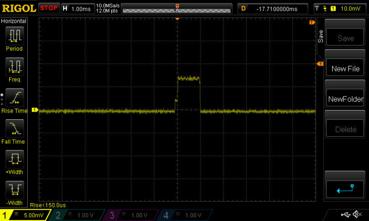
Thanks for the tip. I tried it both ways. The first scope capture below is taken without MODECNF0 enabled on bit 0, and the second is with it enabled on bit 0.
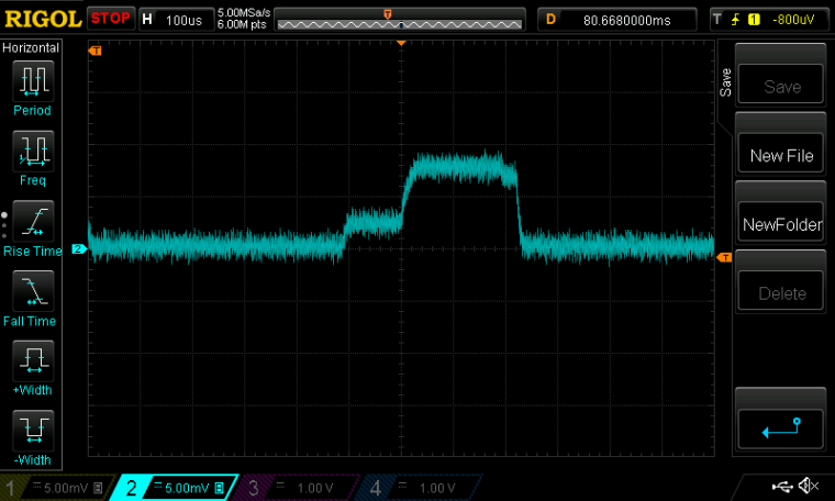
I don't really see any difference. Do you?
Scale: 1mv=1ma. Scope captures of current drawn.Maybe @jokgi can comment? His bio says he's a Senior Field Application Engineer at Nordic Semiconductor.
Maybe he sees (or knows) something that's not apparent about the fast ramp enable bit?
Hello! It looks like you're interested in this conversation, but you don't have an account yet.
Getting fed up of having to scroll through the same posts each visit? When you register for an account, you'll always come back to exactly where you were before, and choose to be notified of new replies (either via email, or push notification). You'll also be able to save bookmarks and upvote posts to show your appreciation to other community members.
With your input, this post could be even better 💗
Register Login