nRF5 action!


  • Hero Member

    @Toyman said in nRF5 Bluetooth action!:

    @NeverDie do you use hwSleep() instead of sleep()?

    Yes.


  • Hero Member

    OK, I found that adding:

      NRF_UART0->ENABLE=0;  //disable UART0
    

    brings the current consumption back down to 2.2ua during sleep. 🙂


  • @NeverDie should it be placed just before hwSleep()?


  • Hero Member

    @Toyman said in nRF5 Bluetooth action!:

    @NeverDie should it be placed just before hwSleep()?

    It's just a possible preliminary piece of the solution, because you'll need to renable UART0 after waking up from sleep. I haven't tested to see whether Serial.print(..) still works after re-enabling, or whether it needs to be re-initialized. Those are details yet to be sorted.

    Or, maybe there's some other way of doing it. At this point, I'm just reporting my finding and tossing it out there as a tantalizing possibility.


  • Contest Winner

    @Toyman said in nRF5 Bluetooth action!:

    @d00616 thx. How do I use the macro? Just put in ISR?

    Yes. Give the event register as parameter.

    Regarding the bug: if read the docs correctly, all nrf51 have the bug

    This bug is listed as PAN#39 and fixed at the end of 2014.


  • Contest Winner

    @NeverDie said in nRF5 Bluetooth action!:

    OK, I found that adding:
    NRF_UART0->ENABLE=0; //disable UART0

    brings the current consumption back down to 2.2ua during sleep.

    Great work. Are you able to build an Pull Request fixing this? This Pull request should also be tested in the condition with a disabled serial port.

    If you need help, please ask. I do the reviews.


  • @d00616 said in nRF5 Bluetooth action!:

    Yes. Give the event register as parameter.

    so, if I have an intterupt atached to pin 1, what shall i put into ISR?
    NRF_RESET_EVENT....;
    Sorry for dumb questions, this is completely new to me.


  • Hero Member

    @d00616 said in nRF5 Bluetooth action!:

    If you need help, please ask.

    What is it that I submit? A diff file or something? And I'm guessing I do it through github?


  • Hero Member

    Just re-enabling the UART isn't enough. Nor are the existing UART related instructions after a wake-up, if UART0 was disabled. It seems to require a re-initialization. Another Serial.begin(BAUDRATE) after wake-up does work. However, I should point out that doing that isn't free, as it adds to wake-up time. So, you may wish to add another "level" of sleep, one which saves more energy while sleeping but at the cost of a longer wake-up. Moreover, the energy consumed during the longer wakeup isn't free either, so if the sleeps are very short, you could lose more energy for using it than not. One may, therefore, also want to calculate the breakeven point to provide guidance on when to use which level of sleep.

    In short, this is more than a simple fix, and the software architect probably needs to consider the bigger picture in order to craft the best solution.


  • Guys,

    Have you seen this?

    Note, that our beloved ebyte is not there, but PTR9618PA is


  • Hero Member

    @Toyman said in nRF5 Bluetooth action!:

    Guys,

    Have you seen this?

    Note, that our beloved ebyte is not there, but PTR9618PA is

    It's useful. But just knowing the module exists is one thing. Finding a source for it is another.


  • @NeverDie I believe, buying non-Chinese modules in retail is virtually impossible, but Xuntong, Skylab and Raytaq are available at Ali.
    For me, the list is more like "quality assurance"


  • Contest Winner

    @Toyman said in nRF5 Bluetooth action!:

    @d00616 said in nRF5 Bluetooth action!:

    Yes. Give the event register as parameter.

    so, if I have an intterupt atached to pin 1, what shall i put into ISR?

    With arduino-nrf5, you can't put nothing into the pin interrupt ISR because the ISR is already defined.

    Sorry for dumb questions, this is completely new to me.

    There are no dumb questions, there are bad answers.


  • Contest Winner

    @NeverDie said in nRF5 Bluetooth action!:

    @d00616 said in nRF5 Bluetooth action!:

    If you need help, please ask.

    What is it that I submit? A diff file or something? And I'm guessing I do it through github?

    There is and document describing the procedure: https://www.mysensors.org/download/contributing

    I think this is a good document to start with. If you have trouble, please ask.


  • Hero Member

    @d00616
    The solution I'm going with, which serves my present needs, is just to put all serial communications code within "DEBUG" compiler directives. So, if I'm not debugging, the issue just goes away, and there's no added overhead. 🙂


  • Hero Member

    @NeverDie said in nRF5 Bluetooth action!:

    @d00616
    The solution I'm going with, which serves my present needs, is just to put all serial communications code within "DEBUG" compiler directives. So, if I'm not debugging, the issue just goes away, and there's no added overhead. 🙂

    Found a shortcut. Instead of doing all that, which is extra work and looks ugly too, I just disabled the UART0 on the first sleep, and then never re-enabled it. It works. Now my sleep current is just 2.1ua, except for the brief pulses every 100ms where the PPI listens for an incoming packet addressed to it. 🙂


  • Hero Member

    I was just checking the nRF51 datasheet, and I don't see much, if any, PPI control available. So, I suppose that's yet another reason for preferring the nRF52....


  • Hero Member

    Nonetheless, I just now measured the sleep current on the cheap nRF51822 that @NCA78 referenced:
    https://www.aliexpress.com/item/NRF51822-04-BLE4-0-Wireless-Bluetooth-Module-TTL-Low-Power-Consumption-3-3V-New/32821044213.html?aff_platform=aaf&cpt=1507850033284&sk=e2Vzr3v&aff_trace_key=fa8ec197f200446fbd58fc8679ffb3bd-1507850033284-07709-e2Vzr3v&terminal_id=29bfb7ff18284b7f96acb3c3884390ce
    It measures at 5ua, which is higher than the 2.1ua of the nRF52832, but still not bad in absolute terms. I was afraid after the discussion of how some nrf51's had a 1ma bug in the hardware that they would be counted among them. Fortunately, it seems not. 🙂


  • @NeverDie The nRF51 is done on a different process then then the nRF52. The nRF52 is on average 50% lower power then the nRF51. The picture of the module shows a nRF51822QFAA Hx part which is a 256k flash, 16k Ram part REV 3. You can see all the revision number here: http://infocenter.nordicsemi.com/topic/com.nordic.infocenter.nrf51/dita/nrf51/compatibility_matrix/nRF51822_ic_revision_overview.html?cp=3_0_1


  • @NeverDie You may wish to check out the nRF51 Reference guide in addition to the datasheet. http://infocenter.nordicsemi.com/pdf/nRF51_RM_v3.0.1.pdf The PPI is located in section 16.


  • Hero Member

    @Jokgi said in nRF5 Bluetooth action!:

    @NeverDie You may wish to check out the nRF51 Reference guide in addition to the datasheet. http://infocenter.nordicsemi.com/pdf/nRF51_RM_v3.0.1.pdf The PPI is located in section 16.

    Thanks! Doesn't look as though the nRF51822's PPI allows for FORK though, whereas the nRF52832 does.


  • @NeverDie actually, I am suprised that many of these modules are available and at the prices lower than Ali.
    For example:
    http://www.fanstel.com/buy/bt832xe
    They claim "BT832XE is the longest range Bluetooth 5 module, 1350 meters between 2 BT832XE with used with ANT060 antenna."
    $23, shipped within US
    Not bad, ah?


  • One must be aware, that the gain of an antenna doesn't come from a magic amplification, but from direction.
    Meaning, the higher the gain of an antenna is, the more directional it is.
    For a sensor, let's say a window switch, that may end up in every mounting position you might imagine, this is NOT what you want.

    Neither do you want that for the gateway, that may be in the middle of the house, and should be able to receive transmissions from all directions.


  • Hero Member

    @Uhrheber
    It does look like they also have a PA on their module: http://www.fanstel.com/bt832x-bluetooth-5-module/

    It's a good find, as it looks as though they have a lot to choose from: http://www.fanstel.com/buy/

    Also, as compared to the chinese vendors, I think it's more likely that they really did pass FCC, since it's based in the US. The fines to US companies for selling non-compliant stuff are pretty severe (enough to bankrupt a small company), whereas (it seems) the chinese vendors can dodge it. Hence, the joke that "CE" stands for "Chinese Exemption".


  • @NeverDie exactly! On top, they have very extensive datasheet with all the results


  • Hero Member

    I just now noticed that fanstel is selling an nRF52840 module: http://www.fanstel.com/buy/bt840f-v1-nrf52840-bluetooth-5-thread-zigbee-module

    That's the first I've seen on the open market (aside from the DK that is). [Edit: won't be shipping until January though]

    I wonder which, if any, of the Fanstel modules contain the DCDC hardware? Their pinout on the 832's does not appear to be as complete as the Ebyte module, so if DCDC is not already on the module, it might be impossible to add after-the-fact.


  • @NeverDie said in nRF5 Bluetooth action!:

    Their pinout on the 832's does not appear to be as complete as the Ebyte module, so if DCDC is not already on the module, it might be impossible to add after-the-fact.

    https://static1.squarespace.com/static/561459a2e4b0b39f5cefa12e/t/59a5a0bbbe42d6d26bd82969/1504026813812/BlueNor_BT840F_datasheets.pdf

    Page 13,
    pin F5


  • Hero Member

    @Toyman Thanks! I'm going to order a couple of the Nordic nRF52840 PDK's to audition now that modules are on the horizon. Shall be interesting to see how the range compares in a normal home environment. Also, 256K RAM and 1M of flash sounds like such a luxury!


  • @NeverDie Note that all the nRF52840 based products being showcased now (including the Fanstel modules) are using the engineering silicon. There is Errata on these parts. Production devices will be available Q1-18.


  • Hero Member

    @Jokgi said in nRF5 Bluetooth action!:

    @NeverDie Note that all the nRF52840 based products being showcased now (including the Fanstel modules) are using the engineering silicon. There is Errata on these parts. Production devices will be available Q1-18.

    Do you advise waiting, or is it sufficiently non-buggy that it's likely to work unless doing something obscure?


  • Hero Member

    @d00616 Problem #1 is that there does not yet appear to be an Arduino board definition for the nR5F2840, as there is already for the nRF52832 and nRF51822. Is that correct? Or does one already exist somewhere? It's critical path to testing code on the nRF52840 PDK.


  • Hero Member

    Hmmm... Looks like there is an nRF52840 "variant": https://github.com/lpercifield/arduino-nRF5/commit/d55d54a1bdc479acc259e131f0f445c5da8e02b3
    Would that work? If so, how exactly should it be added so that it will appear in the Arduino IDE board manager list of boards?


  • @NeverDie the main issue it's "65 commits behind master" so it's outdated in all areas except 840
    Theoretical path is to make a fork of current sandeep's branch and then merge the changes from the repository you found. But given the above, it won't be easy.


  • Hero Member

    Gosh, I'm wishing now that I hadn't ordered the PDK. I guess I'll just return it for a refund. Since it sounds like literally no one else is presently using the 840, I'd rather move forward on the 832. I'm more interested in the 2mbps datarate anyway (for the reason below). And I'm pretty sure PA versions of the nRF52832 will beat the range of an unamplified nRF52840.


  • Hero Member

    @d00616 said in nRF5 Bluetooth action!:

    Great job. If I'm not wrong the method allows nearly 1 year of listening time with a CR2032.

    Yup, based on the latest measurements, I estimate an average current drain of about 25 microamps. So, assuming a CR2032 has 240mah of useable current, that comes out to about 1.1 years of listening time. Or more than 13 years on a pair of Energizer Lithium AA's. Pretty cool. 🙂 And that's listening for a packet once every 100ms. It could last much longer if it were to listen less often.


  • Hardware Contributor

    @NeverDie said in nRF5 Bluetooth action!:

    Gosh, I'm wishing now that I hadn't ordered the PDK. I guess I'll just return it for a refund. Since it sounds like literally no one else is presently using the 840, I'd rather move forward on the 832. I'm more interested in the 2mbps datarate anyway (for the reason below). And I'm pretty sure PA versions of the nRF52832 will beat the range of an unamplified nRF52840.

    I looked at the fanstel modules a while ago, but like guys said above, these are beta mcus with errata. And not arduino uptodate for the same reason i guess.

    I have one 840pdk too. for tests 🙂 with apache mynewt. Because I have only one 840 board I can't tell you about the range because it needs two boards for checking that, two boards with full BLE5 Long range (and 832 is not BLE5 full range).

    No idea about 840 vs 832+PA but 840 is already PA integrated which is pretty cool. It also has some other nice features. Range tests regarding BLE5 long range are impressive imho, indoor or not, and from different mcu manufacturers (some have nice parts).
    I'm not sure though, if 840, is compatible with NRF24. And, as I'm talking about BLE, I prefer to say it again, for others.. BLE is not MySensors 🙂


  • Hero Member

    Are there any examples of how to control the potential BLE5 capabilities of this chip using code developed in the Arduino IDE? I recognize that it's presently a separate thing from MySensors, which is using the proprietary modes to ensure backward compatability to the nRF24, but surely getting some hooks into BLE5--even if it's just high level stuff--would be beneficial wouldn't it?


  • Hero Member

    For instance, how hard would it be to create a simple serial bridge so view serial output on your bluetooth phone, the way @sundberg84 is doing with a specialized bluetooth module: https://forum.mysensors.org/topic/6340/debug-to-a-sd-card-module


  • Contest Winner

    @NeverDie said in nRF5 Bluetooth action!:

    For instance, how hard would it be to create a simple serial bridge so view serial output on your bluetooth phone, the way @sundberg84 is doing with a specialized bluetooth module: https://forum.mysensors.org/topic/6340/debug-to-a-sd-card-module

    For similar functionality, there is an MY_DEBUG_OTA feature in MySensors development branch. You can send log messages to any node in the MySensors network.

    The NRF5 MySensors port is running directly on the MCU hardware. Using the SoftDevice is like running an Operating System. There are limitations using the Hardware and APIs have to use. You are loosing control over the Radio, some Timers and RTC, Crypto components and the memory layout.

    The reason the SoftDevice isn't supported is the old licence model. This model is changed with SDK14.

    In my opinion with MySensors 2.x it isn't meaningful to play with the multiplexing of the radio module. I think this requires more changes in MySensors to handle the time when the MCU is in BLE mode.

    If you are interested implementing a dual stack software, then I think the Arduino Primo port is a good point to start. This is based on the NRF5 SDK. The Primo port has no support for NRF51 devices.

    If you are not restricted to Arduino, you can also see MyNewt or Zephyr. Both have BLE Open Sorurce implementations for the NRF5 MCUs.


  • Hardware Contributor

    I agree with @d00616 points above.
    And, sure bluetooth would be nice for interacting or debugging.

    In my opinion, maybe I'm wrong, for my network, I would prefer MySensors NRF ESB, in general.

    • "more secure" than bluetooth. "harder" to access Mysensors ESB than bluetooth for example, plus some security issue that can happen with bluetooth, phones..
    • more devices in a network

  • Hero Member

    @d00616 What do you foresee regarding the nRF52840? It's presently unsupported.


  • Hero Member

    For those who haven't seen it, this Fanstel nRF52832 module is impressively small:
    alt text
    Looks as though it even includes the antenna!


  • Hero Member

    Good news. The Fanstel 832X (https://static1.squarespace.com/static/561459a2e4b0b39f5cefa12e/t/59a5a03d579fb36451a25f01/1504026688443/BlueNor_BT832X_datasheets.pdf) module contains the sky66112 (http://www.skyworksinc.com/Product/3152/SKY77927-11z-. which has a PA and an LNA on it. The Rx gain is 11dB, and the TX gain is 22dB. So, this should make for a very good gateway module.


  • @NeverDie they even provide a piece of code to properly activate it


  • Contest Winner

    @NeverDie said in nRF5 Bluetooth action!:

    @d00616 What do you foresee regarding the nRF52840? It's presently unsupported.

    In those places where it was obvious, I took the design of the NRF52840 into consideration. I think, when an Arduino port supporting Sketches without SoftDevices is available, then porting is simple. At the moment, I have no plans to expedite an Arduino port.


  • @d00616 said in nRF5 Bluetooth action!:

    when an Arduino port supporting Sketches without SoftDevices is availableI

    I doubt it will ever happen as all 3 major nrf5 arduino implementations all rely on Softdevice (Primo, Adafruit and Sandeep)


  • Hero Member

    @Toyman said in nRF5 Bluetooth action!:

    I doubt it will ever happen as all 3 major nrf5 arduino implementations all rely on Softdevice (Primo, Adafruit and Sandeep)

    I don't follow what you mean. Aren't we already running the MySensors code without installing the softdevice on the nrf51822 and the nrf52832?


  • @NeverDie Sorry, I meant "BLE implementation without Softdevice"


  • Hero Member

    @d00616 said in nRF5 Bluetooth action!:

    when an Arduino port supporting Sketches without SoftDevices is available

    Is it Sandeep who does that port, or you, or...? I don't have a clear picture as to how many people are working on it, or even who is doing what.


  • Hero Member

    @Toyman said in nRF5 Bluetooth action!:

    @NeverDie Sorry, I meant "BLE implementation without Softdevice"

    I guess the way I read this fog of tea leaves is that nothing is going to happen before final silicon on the nRF52840, and even then there's not much motivating an Arduino port for it. And someday it may happen. i.e. I guess the folks who are doing the heavy lifting are generally happy with the nRF52832 and its capabilities? I probably wouldn't be comfortable relying purely on the nRF52832 if it weren't for the amplified modules that fill the gap. I haven't tried the Fanstel one, but on paper it looks like it's probably good enough for my modest needs.


  • @NeverDie Are you talking about MYS or in general? Because, currently there are two completely different approaches to nrf-arduino. One is based on softdevice (or in broader terms, on SDK) while another works direcly with hardware.
    For MYS, our only hope is d00616, if he doesn't do it, chances somebody will apapt 52840 to MYS are negligible.
    Frankly, MYS don't need it, but that's just my opinion.


  • Contest Winner

    @Toyman said in nRF5 Bluetooth action!:

    For MYS, our only hope is d00616, if he doesn't do it, chances somebody will apapt 52840 to MYS are negligible.

    Please don't be so pessimistic. I expect some very small changes to MySensors to support the NRF52840 platform when arduino-nrf5 is ported to the new NRF5 MCU generation. When arduino-nrf5 supports the NRF52840 platform, I do some tests with the 840DK, I already have.

    Looking back to the NRF52832, I think in 6-9 month we can buy NRF52840 modules with production ready chips. I think there is no reason for panic.


  • Hero Member

    @Toyman
    D00616's explanation increases my optimism considerably because: the people doing the NRF-arduino port care a lot about bluetooth. They'll want to see it through for that reason, because the 840 has much more bluetooth capabilities. Then, once they get that part done, like D00616 says, it will be ripe for porting to MYS. So really, all the interests are aligned. I don't think it will languish. At least, that's the narrative I'm going with.


  • Hero Member

    Received this today:
    0_1508192352279_RFaxis.jpg
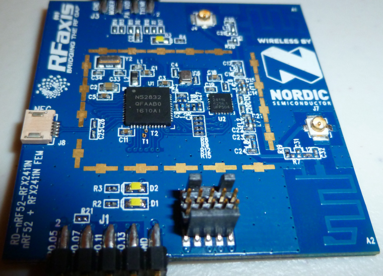
    I thought it might have the same PA-LNA as the sky66112 (which also supports antenna diversity) used on the Fanstel, but the lettering suggests otherwise.


  • Hero Member

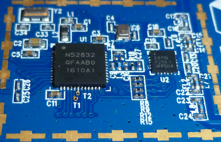
    Here's a better close-up of the chips themselves, which is easier to read:
    0_1508192892369_RFaxis2.jpg


  • Hero Member


  • @NeverDie As I may have mentioned before. This was a limited run of prototypes (100 total) designed by RF AXIS and built by Xungtong.. My understanding is that this device is being deemphasized by Skyworks in favor of the SKY661xx family..


  • Hero Member

    @Jokgi
    Do you happen to have the datasheet? The closest I've been able to find is: http://www.mouser.com/ds/2/472/rfaxis_RFX2411N Eval Board Summary and Technical N-952564.pdf
    which isn't quite on-point, but I may have to make do with.

    I had thought it would somehow automagically select the better antenna for receiving, but it looks like it wants me to make that selection myself. So, this may work better with longer preambles I suppose, to give enough time to measure the RSSI on each and then decide.


  • @NeverDie The datasheet for the RFX2411N?


  • @Jokgi The only datasheet I have states that it is confidential. Therefore I cannot share it. However if you contact Skyworks they may be able to get you a copy. At the time I received it one needed to fill out a form on RF Axis site and then the file would be sent. Are there any particular parameters you are interested in?


  • Hero Member

    @Jokgi

    Just which pins on the nRF52832 are connected to which control pins on the RF Front End. I just now checked with a continuity meter, and it looks like none of them are. So, it would appear that I'll need to wire the pin connections external to the PCB, which is weird, but maybe that's just how it is.


  • Hardware Contributor

    @scalz said in nRF5 Bluetooth action!:

    In my opinion, maybe I'm wrong, for my network, I would prefer MySensors NRF ESB, in general.

    • more devices in a network

    Not with bluetooth mesh, you can have thousands of nodes 😉


  • @NeverDie Hello, If you are referring to that Prototype Board with the Nordic logo on it then it was being controlled by GPIO and by the Bluetooth Low Energy stack (Softdevice) You can read more about it here.. https://devzone.nordicsemi.com/blogs/831/palna-support-in-s132/.
    As I mentioned before. there is no good way to control the PA in a proprietary mode, only when using BLE. Regardless, I have asked if it is ok to share the schematic that relates to that PA board and I will let you all know. And about the question about antenna switching. This was never implemented in the Softdevice. Any antenna switching would need to be done in the application.
    See if this chart helps.

    0_1508212131505_I-O for nRF52832 - RFX2411n.JPG


  • Hardware Contributor

    @Nca78 said in nRF5 Bluetooth action!:

    Not with bluetooth mesh, you can have thousands of nodes 😉

    not without some latency 🙂
    but I agree, I forgot this new mode 👍
    I just prefer to keep my nodes "hidden" for security. so no BLE network for me. I will just have some restricted access to it I think..


  • Hero Member

    @Jokgi
    Thanks! Yes, those three tables are exactly what I was looking for.


  • Hero Member


  • Hero Member

    I just noticed a very clever thing that Fanstel did: their nRF52 modules all have the same land pattern and pinout. That means you can upgrade from a regular nRF52832 to a power amplified version, or even an NRF52840 (when they become available), by just dropping the upgrade module into the same position on the PCB. i.e. you can run all the different modules from the same PCB design. Pretty cool. I like it. 🙂


  • Mod

    @NeverDie but how will you spend all the time you save by not having to create new boards all the time? 😉


  • Hero Member

    @mfalkvidd said in nRF5 Bluetooth action!:

    @NeverDie but how will you spend all the time you save by not having to create new boards all the time? 😉

    Yeah, not just that, but also not having to waste all that time waiting for each new board to come back from the fab. 🙂


  • Hero Member

    @NeverDie said in nRF5 Bluetooth action!:

    I had thought it would somehow automagically select the better antenna for receiving, but it looks like it wants me to make that selection myself. So, this may work better with longer preambles I suppose, to give enough time to measure the RSSI on each and then decide.

    I suppose an easy solution would be to have a remote node send repeated packets, and I just program the RFAxis to toggle between its two antennas after allowing sufficient dwell time per antenna. That way it's more likely to receive at least one of the packets.

    All in all, though, I think maybe having two separate radio receivers (since they're cheap anyway) for a gateway is probably better than having one radio receiver, with the burden on the firmware to select which antenna to receive on.

    Any thoughts on this?


  • @NeverDie 0_1508367805179_RD-nRF52-RFX2411N-REV2.zip Hello All -- For your viewing enjoyment. The Schematic and layout files for that nRF52840 and RFX2411n board you have. (If it is version 2 which did have the big Nordic logo on it. )
    I think you may know this already but this bears repeating. This is not a Nordic board. Nordic Semiconductor's tech support will probably not know anything about this board. Also there is a difference between the RFX2411 and the nRF2411N. (N for Nordic) It is not the same device.


  • Hero Member

    On a different topic, regarding the Ebyte modules, I'm noticing that they are much more likely to miss a packet if being run at 2.1v than if it's being run at, say, 3.3v. I've tried this now on two different modules, and the results are repeatable. It's a preliminary result, because so far I've only tested it with respect to the "listen mode."


  • @NeverDie Is this the board with a PA on it or stand alone nRF5x part? If with a PA what is the rated voltage of the device?

    Depending on the Nordic part the nRF5x can run from 1.7 (or 1.8) to 3.6vdc. Note that the nRF51 cannot run with the DC / DC under 2vdc. The nRF52 does not have that restriction and the DC/DC can be used throughout the full voltage range..


  • Hero Member

    @Jokgi said in nRF5 Bluetooth action!:

    Is this the board with a PA on it or stand alone nRF5x part?

    I observed it on Ebyte's E73-2G4M04S on this board: https://www.openhardware.io/view/471/Ebyte-nRF52832-Small-Breakout-Board
    while running in DCDC mode. The E73-2G4M04 has no PA.

    For now, I'm just reporting the finding, in case anyone else has noticed it. Also, it's a very early result. If there's no known reason to suspect the nRF52832 as a possible cause (i.e. no erratas or the like), then I'm glad to hear it.


  • Hero Member

    OK, I fixed the problem by increasing the size of the listen window by another 30 microseconds (which is the smallest granularity that the RTC offers). What this probably means is that some aspect of the wake-up process (for instance, perhaps the amount of time it takes for the high frequency oscillator to come up to speed) is taking a wee bit longer when the module is powered at the lower voltage than when it is powered at 3.3v.


  • Hero Member

    @Jokgi said in nRF5 Bluetooth action!:

    @NeverDie Hello, If you are referring to that Prototype Board with the Nordic logo on it then it was being controlled by GPIO and by the Bluetooth Low Energy stack (Softdevice) You can read more about it here.. https://devzone.nordicsemi.com/blogs/831/palna-support-in-s132/.
    As I mentioned before. there is no good way to control the PA in a proprietary mode, only when using BLE. Regardless, I have asked if it is ok to share the schematic that relates to that PA board and I will let you all know. And about the question about antenna switching. This was never implemented in the Softdevice. Any antenna switching would need to be done in the application.
    See if this chart helps.

    0_1508212131505_I-O for nRF52832 - RFX2411n.JPG

    The only definition I've found for PDET is "Analog Voltage Proportional to the PA Power Output ." I'm not sure what that means. So, I set P0.02 to HIGH, which in this instance is 3.3v. However, I'm only getting relatively weak Tx power emitted. Is there anything else I should be doing? For instance, should I be supplying external voltage to the PDET pin directly?

    Here's the code I'm currently using to setup for transmission:

      myNrf5_pinMode(2,OUTPUT_H0H1); //PDET
      myNrf5_pinMode(20,OUTPUT_H0H1); //SWANT
      myNrf5_pinMode(24,OUTPUT_H0H1); //TXEN   
      myNrf5_pinMode(23,OUTPUT_H0H1); //RXEN
      myNrf5_pinMode(22,OUTPUT_H0H1); //MODE
    
      digitalWrite(20,HIGH);  //select one of the antenna's.
      digitalWrite(23,LOW);  //disable RXEN
      digitalWrite(24,HIGH);  //enable TXEN
      digitalWrite(22,LOW);  //disable MODE
      digitalWrite(2,HIGH);  //set the analog voltage for PDET as high as possible
    

  • Hero Member

    @NeverDie said in nRF5 Bluetooth action!:

    For instance, should I be supplying external voltage to the PDET pin directly?

    I tried that just now, and it made no difference.

    I also tried powering the PA_VDD pin externally at 3.3v, and that didn't help either. Does that pin expect higher voltages?


  • Hero Member

    @Jokgi said in nRF5 Bluetooth action!:

    @NeverDie 0_1508367805179_RD-nRF52-RFX2411N-REV2.zip Hello All -- For your viewing enjoyment. The Schematic and layout files for that nRF52840 and RFX2411n board you have. (If it is version 2 which did have the big Nordic logo on it. )
    I think you may know this already but this bears repeating. This is not a Nordic board. Nordic Semiconductor's tech support will probably not know anything about this board. Also there is a difference between the RFX2411 and the nRF2411N. (N for Nordic) It is not the same device.

    Just now noticed that the schematic explains PDET. It's "Optional Antenna Power Monitoring." So, I take that to mean that it's output from the board, not input to it.

    Also, the schematic indicates that the board has the DCDC inductors built into it, so that's good.


  • Hero Member

    Aha! Apparently the RFaxis defaults not to the trace antenna on the board, but rather to the external, connected antenna. So, I hooked that up, and now it's working like a champ. I can now safely say that it definitely has a much better range than a non-PA nRF52832 module. And, of course, I'm running it at 2mbps. 🙂

    The other nice thing is that even if I transmit continuously (i.e. 100% duty Tx cycle), the chips don't get hot. I'm impressed. I tried doing that with a LoRa module once, and it got too hot to even touch.

    It will be fun to check the range when there's a PA+LNA nRF52832 on both ends of the link.


  • Hero Member

    And here it is:
    0_1508440744687_RFaxis3.jpg


  • Hero Member

    Of course, I couldn't stop until I tried hooking it up to the 4w boost amplifier:
    0_1508445375879_RFaxis4.jpg
    Wow! That really kicks tail. I don't think there's a nook or cranny anywhere that I don't get a great signal now, and all from a single gateway. 🙂


  • Hero Member

    I just now ordered a number of Fanstel modules to go with the breakout boards I recently posted. It's worth noting that Fanstel's lowest cost nRF52832 module is only $3.75, which is lower than the Ebyte module: http://www.fanstel.com/buy/bt832-ble42-hardware-ready-for-bluetooth-5-module-2fhya
    I ordered one, and I'll see how it compares in actual use.


  • Hardware Contributor

    @NeverDie said in nRF5 Bluetooth action!:

    It's worth noting that Fanstel's lowest cost nRF52832 module is only $3.75, which is lower than the Ebyte module: http://www.fanstel.com/buy/bt832-ble42-hardware-ready-for-bluetooth-5-module-2fhya

    interesting for US customers only I think. Because last time I looked, shipping were too expensive (plus add extra shipping fee like customs etc.).


  • Hardware Contributor

    @NeverDie said in nRF5 Bluetooth action!:

    It's worth noting that Fanstel's lowest cost nRF52832 module is only $3.75, which is lower than the Ebyte module: http://www.fanstel.com/buy/bt832-ble42-hardware-ready-for-bluetooth-5-module-2fhya
    I ordered one, and I'll see how it compares in actual use.
    It's woth noting that despite it's "832" name it's in fact an nrf52810 😛

    @scalz said in nRF5 Bluetooth action!:

    interesting for US customers only I think. Because last time I looked, shipping were too expensive (plus add extra shipping fee like customs etc.).
    43$ shipping if you're not in the US. And with DHL meaning (at least for me) 10 extra dollars of DHL fee for custom processing + highest tax possible.


  • Hero Member


  • Hero Member

    It's too bad Fanstel's shipping rates outside the US are high. I received the modules I ordered from Fanstel in just a couple of days. I'll try them out after I receive the PCB's from OSH PARK, which should happen in about another 1-2 weeks. The pinout for Fanstel's "micro" version (BC832) is different, and obviously the land pattern is much smaller, so I just now did a separate breakout board for it and sent it to the fab.

    I'm trying to think now as to whether I'll have any future need for nRF24L01's. The very small and cheap nRF51822 seems to supplant it now with its 4dbm higher Tx power, and the nRF52 affords lower current consumption while in Tx or Rx, because of its DCDC option.


  • Hero Member

    @d00616 Is it still the case that we're limited to a single interrupt? For instance, I'd like to put the nRF52832 to wake-up periodically as a heartbeat where it reports its battery level, and I also want it to wake-up if a particular pin goes HIGH (e.g. if a PIR sensor is triggered). Presently I'm using the RTC to provide the one interrupt, and I use the PPI to create an RTC interrupt if it detects that the PIR sensor pin has gone HIGH. Then the interrupt code must determine the true cause of the interrupt. It would be cleaner if I could separate them into separate interrupts. This is just a simple example to explain what I mean by the question.


  • @NeverDie said in nRF5 Bluetooth action!:

    It's too bad Fanstel's shipping rates outside the US are high

    No issue for me as I am a using a mail forwarder(s) and I can highly recommend them to others. Bringing nrf52Dk from Arrow to Russia costed me $10 (inter-US shipping is free at Arrow).
    I am considering switching to Fanstel modules completely, especially to their PA+LNA ones


  • Contest Winner

    @NeverDie said in nRF5 Bluetooth action!:

    @d00616 Is it still the case that we're limited to a single interrupt? For instance, I'd like to put the nRF52832 to wake-up periodically as a heartbeat where it reports its battery level, and I also want it to wake-up if a particular pin goes HIGH (e.g. if a PIR sensor is triggered). Presently I'm using the RTC to provide the one interrupt, and I use the PPI to create an RTC interrupt if it detects that the PIR sensor pin has gone HIGH. Then the interrupt code must determine the true cause of the interrupt. It would be cleaner if I could separate them into separate interrupts.

    You can wake up the MCU via:

    • GPIO pin sense; used for sleep()
    • GPIOTE; consumes less engergy but pin must be dedected in software (0.1µA-0.5µA)
    • LPCOMP (0.5µA)
    • QDEC (5µA)

    The interrupts for LPCOMP and QDEC are not allocated by the arduino-port. I think the LPCOMP is a good point to start with.


  • Hardware Contributor

    @Toyman said in nRF5 Bluetooth action!:

    Bringing nrf52Dk from Arrow to Russia costed me $10 (inter-US shipping is free at Arrow).

    Do they ask you for shipment fee directly to Russia ?
    I'm in Vietnam and bringing nrf52DK from Arrow was free, like everything I order from them, and over US$20 it's even express shipment (By the way they have a 25% flash sale right now !)

    I'm interested on info on your mail forwarder if it's not only for Russia.


  • @Nca78 Arrow ships free to Russia, but only to companies, not to direct consumers this is linked to the fact they use couriers (DHL/Fedex) and not vanilla USPS.
    Have a look at www.shipito.com, it's not the one I am currently using, but Shipito works with the whole world. Pricing might be a bit steep, but I haven't looked at it for a long time.


  • http://blog.nordicsemi.com/getconnected/power-consumption-explained?utm_campaign=Blog update notifications&utm_source=hs_email&utm_medium=email&utm_content=57717514&hsenc=p2ANqtz-9HxcPCGqL9z_8UZBj38TZu8vg-vE-JmEgmzOlt-uiiGj32PO4Vm0brgVaCxtEly5tGV5aioj1vJezIbGK-xZVXV6zxQ&_hsmi=57717514


  • Had the nrf52dk shipped from arrow to the Netherlands. Because it was above 22 euro( something like that) DHL had to let it apply tax and some administration cost.

    The board costed 28 euro(inc shipping). The tax office estimate was that is was around 120 euro??? so they charged me a little to much. I filled in some forms to get some of the taxes back.

    When the board arrived I had to pay DHL 43 euro . So getting it though customes cost more than the board itself. 😏


  • Hardware Contributor

    @Omemanti said in nRF5 Bluetooth action!:

    When the board arrived I had to pay DHL 43 euro .
    DHL is selling it's shipment service cheaper to shops so the cost seems interesting for buyer. But their trick is to force you to pay some "service fee" when you receive your parcel in addition to custom taxes. This is borderline scam IMHO as this fee is mandatory and has a fixed value for each destination country, so DHL should include it upfront when customer orders.
    No more DHL shipment for me.


  • Hero Member

    @d00616 said in nRF5 Bluetooth action!:

    @NeverDie said in nRF5 Bluetooth action!:

    @d00616 Is it still the case that we're limited to a single interrupt?  For instance, I'd like to put the nRF52832 to wake-up periodically as a heartbeat where it reports its battery level, and I also want it to wake-up if a particular pin goes HIGH (e.g. if a PIR sensor is triggered).  Presently I'm using the RTC to provide the one interrupt, and I use the PPI to create an RTC interrupt if it detects that the PIR sensor pin has gone HIGH.  Then the interrupt code must determine the true cause of the interrupt.  It would be cleaner if I could separate them into separate interrupts. 
    

    You can wake up the MCU via:

    • GPIO pin sense; used for sleep()
    • GPIOTE; consumes less engergy but pin must be dedected in software (0.1µA-0.5µA)
    • LPCOMP (0.5µA)
    • QDEC (5µA)

    The interrupts for LPCOMP and QDEC are not allocated by the arduino-port. I think the LPCOMP is a good point to start with.

    I have it now where LPCOMP does detect pin AIN1 (i.e. pin P0.03) going HIGH, but it still doesn't wake-up the MCU, and the interrupt code never runs. I could use the PPI to trigger an RTC interrupt when it detects the NRF_LPCOMP->EVENTS_UP event, which would wake up the MCU, but then I'm back to square one. Is that the best that can be done given the current state of the software?

    #define MY_CORE_ONLY
    
    #include <nrf.h>
    #include <MySensors.h>
    
    uint32_t blinkCounter=0;
    uint32_t interruptCounter=0;
    bool button_pressed=false;
    
    void setup() {
      Serial.begin(9600);
      Serial.println();
      Serial.println("Starting...");
    
      // Enable interrupt
      NVIC_SetPriority(LPCOMP_IRQn, 15);
      NVIC_ClearPendingIRQ(LPCOMP_IRQn);
      NVIC_EnableIRQ(LPCOMP_IRQn);
    
      hwPinMode(LED_BUILTIN,OUTPUT_H0H1);
      //hwPinMode(PIN_BUTTON1,INPUT);
      NRF_LPCOMP->PSEL=1; // monitor AIN1 (pin P0.03).
      while (!(NRF_LPCOMP->PSEL==1)) {} //wait until confirmed
      NRF_LPCOMP->REFSEL=3;  // choose 1/2 VDD as the reference voltage
      while (!(NRF_LPCOMP->REFSEL==3)) {} //wait until confirmed
      NRF_LPCOMP->INTENSET=B0100;  //Enable interrupt for UP event
      while (!(NRF_LPCOMP->INTENSET==B0100)) {} //wait until confirmed
      NRF_LPCOMP->ENABLE=1;  //Enable LPCOMP
      while (!(NRF_LPCOMP->ENABLE==1)) {} //wait until confirmed
      NRF_LPCOMP->TASKS_START=1;  //start the LPCOMP
      while (!(NRF_LPCOMP->EVENTS_READY)) {}  //wait until ready
    }
    
    
    void loop() {
      Serial.print(blinkCounter++);
      Serial.println("HIGH");
      digitalWrite(LED_BUILTIN,HIGH);
      delay(20);
    
    /*
      if (NRF_LPCOMP->EVENTS_UP) {
        digitalWrite(LED_BUILTIN,HIGH);
        delay(2000);
        NRF_LPCOMP->EVENTS_UP=0;  //Clear the semaphore
      }
      */
    
      if (button_pressed) {
        digitalWrite(LED_BUILTIN,HIGH);
        delay(2000);
        button_pressed=false;  //Clear the semaphore
        NRF_LPCOMP->EVENTS_UP=0;  //Clear the semaphore
      }
      
      digitalWrite(LED_BUILTIN,LOW);
      hwSleep(5000);
    }
    
    
    // * Reset events and read back on nRF52
    //* http://infocenter.nordicsemi.com/pdf/nRF52_Series_Migration_v1.0.pdf
     
    #if __CORTEX_M == 0x04
    #define NRF5_RESET_EVENT(event)                                                 \
            event = 0;                                                                   \
            (void)event
    #else
    #define NRF5_RESET_EVENT(event) event = 0
    #endif
    
    
    // This must be in one line
    //extern "C" { void GPIO_IRQHandler(void) {interruptCounter++; NRF5_RESET_EVENT(NRF_RTC0->EVENTS_OVRFLW); NRF_RTC0->EVENTS_OVRFLW=0; }}
    extern "C" { void LPCOMP_IRQHandler(void) {button_pressed=true; interruptCounter++; NRF5_RESET_EVENT(NRF_LPCOMP->EVENTS_UP); NRF_LPCOMP->EVENTS_UP=0; }}
    

  • Hero Member

    Getting closer... The LPCOMP interrupt code does run, but the main loop doesn't resume until the RTC timer makes it resume because the programmed time interval has expired.

    I know this is true because if, during sleep, I make AIN1 go HIGH, and then LOW, then when the MCU later wakes up because of the RTC, it so indicates by making the LED go HIGH for 2 seconds. However, even though there's now solid proof that the LPCOMP interrupt hardware does execute, the main loop doesn't immediately resume, as it does when the RTC times out.

    So.... How to make the main loop immediately resume whenever LPCOMP goes UP?


  • Hero Member

    Well, I have to re-build the timer part of this, and clean up the code, but at least now a PIR sensor trigger will immediately wake-up the MCU. That's progress! Unfortunately, current drawn during sleep is now 456ua, which is much higher than it should be.

    #define MY_CORE_ONLY
    
    #include <nrf.h>
    #include <MySensors.h>
    
    uint32_t rtcInterruptCounter=0;
    uint32_t buttonPressInterruptCounter=0;
    bool button_pressed=false;
    
    
    void myHwSleepPrepare(unsigned long ms)
    {
      // Idle serial device
      NRF_UART0->TASKS_STOPRX = 1;
      NRF_UART0->TASKS_STOPTX = 1;
      NRF_UART0->TASKS_SUSPEND = 1;
      //NRF_UART0->ENABLE=0;  //disable UART0
    
      //NRF_CLOCK->TASKS_HFCLKSTOP = 1;
      
      // Enable low power sleep mode
      NRF_POWER->TASKS_LOWPWR = 1;
    
    }
    
    // Sleep in System ON mode
    inline void doTheSleep()
    {
      __WFE();
      __SEV();
      __WFE();
    }
    
    void myHwSleepEnd(unsigned long ms)
    {
      // Start HFCLK
      //if (nrf5_pwr_hfclk) {
      if (false) {
        NRF_CLOCK->EVENTS_HFCLKSTARTED = 0;
        NRF_CLOCK->TASKS_HFCLKSTART = 1;
        while (NRF_CLOCK->EVENTS_HFCLKSTARTED == 0)
          ;
        // Enable low latency sleep mode
        //NRF_POWER->TASKS_CONSTLAT = 1;
      }
    }
     
    void myHwSleep(unsigned long ms)
    {
      myHwSleepPrepare(ms);
      doTheSleep();
      //now sleeping
      myHwSleepEnd(ms);
    
    }
    
    
    void setup() {
      //Serial.begin(9600);
      //Serial.println();
      //Serial.println("Starting...");
    
      
        // Enable interrupt
      NVIC_SetPriority(LPCOMP_IRQn, 15);
      NVIC_ClearPendingIRQ(LPCOMP_IRQn);
      NVIC_EnableIRQ(LPCOMP_IRQn);
      
      hwPinMode(LED_BUILTIN,OUTPUT_H0H1);
      //hwPinMode(PIN_BUTTON1,INPUT);
      NRF_LPCOMP->PSEL=1; // monitor AIN1 (pin P0.03).
      while (!(NRF_LPCOMP->PSEL==1)) {} //wait until confirmed
      NRF_LPCOMP->REFSEL=3;  // choose 1/2 VDD as the reference voltage
      while (!(NRF_LPCOMP->REFSEL==3)) {} //wait until confirmed
      NRF_LPCOMP->INTENSET=B0100;  //Enable interrupt for UP event
      while (!(NRF_LPCOMP->INTENSET==B0100)) {} //wait until confirmed
      NRF_LPCOMP->ENABLE=1;  //Enable LPCOMP
      while (!(NRF_LPCOMP->ENABLE==1)) {} //wait until confirmed
      NRF_LPCOMP->TASKS_START=1;  //start the LPCOMP
      while (!(NRF_LPCOMP->EVENTS_READY)) {}  //wait until ready
    
      //NRF_PPI->CH[0].EEP = (uint32_t)&NRF_LPCOMP->EVENTS_UP;  //If PIR sensor is triggered
      //NRF_PPI->CH[0].TEP = (uint32_t)&NRF_RTC0->TASKS_TRIGOVRFLW;  //make the RTC wake-up the MCU
    
      //NRF_PPI->CHENSET=B00000001; //enable Channel 0.
      
      NRF_RTC0->INTENSET = B10;  //interrupt MCU if an OVRFLW is detected.
      while (NRF_RTC0->INTENSET != B10) {}  //wait until confirmed
    
    }
    
    
    void loop() {
      //Serial.print(blinkCounter++);
      //Serial.println("HIGH");
      digitalWrite(LED_BUILTIN,HIGH);
      delay(20);
    
    /*
      if (NRF_LPCOMP->EVENTS_UP) {
        digitalWrite(LED_BUILTIN,HIGH);
        delay(2000);
        NRF_LPCOMP->EVENTS_UP=0;  //Clear the semaphore
      }
      */
    
      if (button_pressed) {
        digitalWrite(LED_BUILTIN,HIGH);
        delay(2000);
        button_pressed=false;  //Clear the semaphore
        NRF_LPCOMP->EVENTS_UP=0;  //Clear the semaphore
      }
      
      digitalWrite(LED_BUILTIN,LOW);
      myHwSleep(5000);
    }
    
    
    // * Reset events and read back on nRF52
    //* http://infocenter.nordicsemi.com/pdf/nRF52_Series_Migration_v1.0.pdf
     
    #if __CORTEX_M == 0x04
    #define NRF5_RESET_EVENT(event)                                                 \
            event = 0;                                                                   \
            (void)event
    #else
    #define NRF5_RESET_EVENT(event) event = 0
    #endif
    
    
    // This must be in one line
    extern "C" { void RTC0_IRQHandler(void) {rtcInterruptCounter++; NRF5_RESET_EVENT(NRF_RTC0->EVENTS_OVRFLW); NRF_RTC0->EVENTS_OVRFLW=0; }}
    extern "C" { void LPCOMP_IRQHandler(void) {button_pressed=true; buttonPressInterruptCounter++; NRF5_RESET_EVENT(NRF_LPCOMP->EVENTS_UP); NRF_LPCOMP->EVENTS_UP=0; }}
    

  • Hero Member

    Aha! Most likely the high current draw is from the high frequency clock, which I need to turn off prior to sleep but haven't done yet.


  • Hero Member

    Anyhow, the basic question remains and boils down to this: Can I have both

        // Enable interrupt
      NVIC_SetPriority(LPCOMP_IRQn, 15);
      NVIC_ClearPendingIRQ(LPCOMP_IRQn);
      NVIC_EnableIRQ(LPCOMP_IRQn);
    

    AND an equivalent incantation for the RTC both active at the same time? Or am I forced into having it be just one or the other?


  • @NeverDie Did you manage to get more than 10m ? maybe by another modules.

    I thought the nrf52 will have better range !


Log in to reply
 

Suggested Topics

0
Online

11.2k
Users

11.1k
Topics

112.5k
Posts