Supercap Solar Powered Mysensors nodes as cheap as possible
-
Maybe a schematic of your setup would help the readers of your thread make informed comments. Otherwise, it starts to become 20 questions, if you know what I mean. People on this forum love to look at schematics.
@NeverDie https://www.openhardware.io/view/389/EasyNewbie-PCB-RFM69-HWW-edition-for-MySensors "battery operation", I use this setup with the code like on this page https://www.mysensors.org/build/battery#measuring-and-reporting-battery-level
-
@NeverDie https://www.openhardware.io/view/389/EasyNewbie-PCB-RFM69-HWW-edition-for-MySensors "battery operation", I use this setup with the code like on this page https://www.mysensors.org/build/battery#measuring-and-reporting-battery-level
@gohan
Well, if 0.1uf is normally sufficient, why wouldn't it be in your case?There's an easy way to test my hypothesis: why don't you try powering your setup from some fresh batteries (or a high quality supercap if you have one) and see if there's still the voltage discrepancy? If not, then it's the ESR of your cheap supercap. If it's still there, then maybe you just need to calibrate?
-
@gohan said in Supercap Solar Powered Mysensors nodes as cheap as possible:
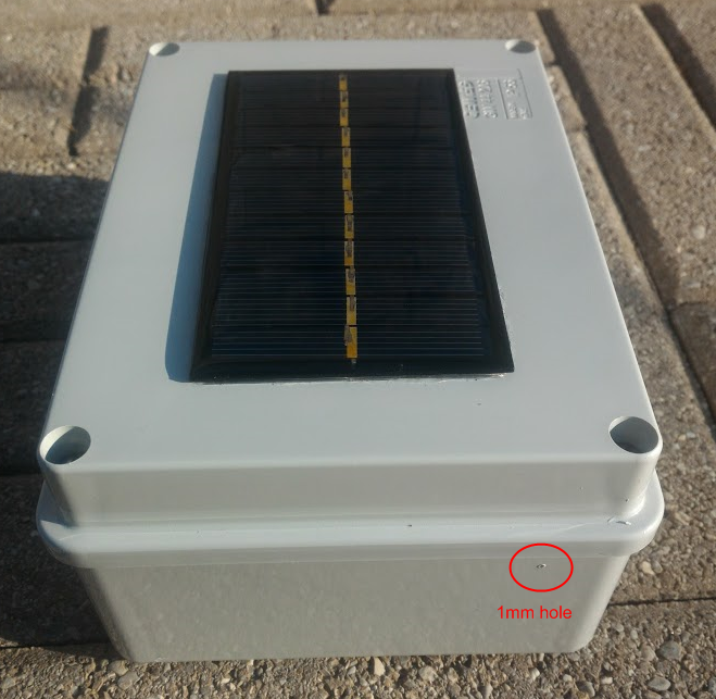
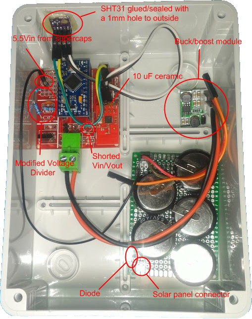
I have uploaded 2 pictures of the solar powered 5.5V node
Uploaded to where? I don't see anything.Nevermind, I see it now at the beginning of the thread. -
I'm currently testing the single 100F cap but it seems the buck boost is barely able to charge the supercap in direct sunlight, while the solar panel connected directly to the 5.5v supercaps was working much better. I'll have to try with a normal buck converter as it seems now the boost mode is making the solar panel working on a voltage too low that doesn't produce much power.
-
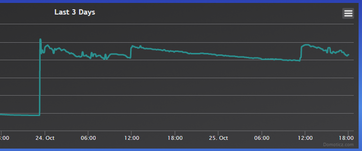
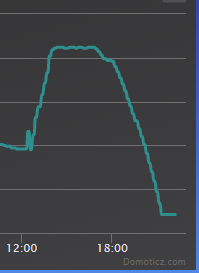
I replaced the buck-boost module with a simple buck converter and it seems to work much better since the operating voltage is from 4.5V to 23V. As you can see from the below picture, the buck-boost barely charged the cap while in direct sunlight while the buck converter was able to charge the cap in a short time even with a cloudy day.
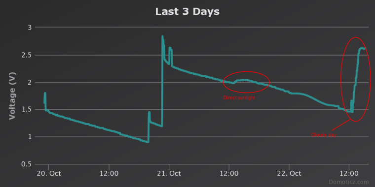
I am also very happy since I set the output voltage to 2.62V on the buck converter and I actually get 2.62V reported by the arduino.
I also forgot to say that I am using a booster like showed in @sundberg84 project link text -
I replaced the buck-boost module with a simple buck converter and it seems to work much better since the operating voltage is from 4.5V to 23V. As you can see from the below picture, the buck-boost barely charged the cap while in direct sunlight while the buck converter was able to charge the cap in a short time even with a cloudy day.
I am also very happy since I set the output voltage to 2.62V on the buck converter and I actually get 2.62V reported by the arduino.
I also forgot to say that I am using a booster like showed in @sundberg84 project link text@gohan I suspect it's "working" because the voltage on your boost converter is higher than 2.62v from the solar panel anyway at the time that it's charging. Even on a cloudy day, it's not hard to get more than 2.6v on a 6v solar panel.
-
The booster is only from the supercap to the node to keep a steady 3.3v. The solar panel if feeding the buck converter directly so it will start charging when panel is providing around 4,5v. It is a double conversion, I know, but efficiency is not the goal.
-
Now voltage stays between 2 and 2.4V (it should be 2.62V but I need to adjust the buck converter and add 0.2V as they are lost though the diode now). I don't understand why the voltage is so unstable now during discharge hours -
-
@xydix In what sense do you mean optimal? I think what separates our approaches is that gohan wants to buy readymade parts off aliexpress and, if possible, connect them with dupont wires. So, if that rings true for you, then you will probably find his approach more optimal.
-
@xydix In what sense do you mean optimal? I think what separates our approaches is that gohan wants to buy readymade parts off aliexpress and, if possible, connect them with dupont wires. So, if that rings true for you, then you will probably find his approach more optimal.
@NeverDie Doesn't matter for me. I have seen your boards on openhardware for solar panels. Interesting.
In many cases an custom PCB get pretty expensive if you just want 1 or 2 board because buy all components required, these are often is selled in 10 pcs or more.
In my case, I want something that works, then if i can get away with just an LDO on an protoboard im fine with that.
I try to build as cheap nodes as possible.
Then if i can find cheap stuff in aliexpress that is doing the job, thats fine.
Have you had any good results useing solar panel indoors? -
@NeverDie Doesn't matter for me. I have seen your boards on openhardware for solar panels. Interesting.
In many cases an custom PCB get pretty expensive if you just want 1 or 2 board because buy all components required, these are often is selled in 10 pcs or more.
In my case, I want something that works, then if i can get away with just an LDO on an protoboard im fine with that.
I try to build as cheap nodes as possible.
Then if i can find cheap stuff in aliexpress that is doing the job, thats fine.
Have you had any good results useing solar panel indoors?@xydix said in Supercap Solar Powered Mysensors nodes as cheap as possible:
Have you had any good results useing solar panel indoors?
Definitely yes. A typical $1 6v solar panel together with an LDO and diode works fine. At least for me. Gohan is exploring something altogether different, and I'd rather not derail his thread. So, if you want more detail, just read the thread I wrote previously.
Hello! It looks like you're interested in this conversation, but you don't have an account yet.
Getting fed up of having to scroll through the same posts each visit? When you register for an account, you'll always come back to exactly where you were before, and choose to be notified of new replies (either via email, or push notification). You'll also be able to save bookmarks and upvote posts to show your appreciation to other community members.
With your input, this post could be even better 💗
Register Login