Supercap Solar Powered Mysensors nodes as cheap as possible


  • Mod

    I am currently testing a couple of concepts to power an outdoor node for temperature and humidity with readily available stuff:

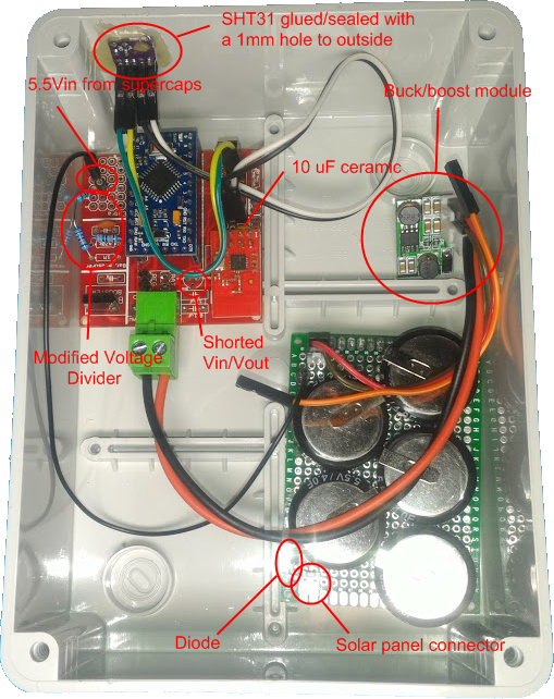
    • 2.7v: using this supercap + this module, just hook up any 6v solar panel to Vin and the supercap on the Vout with a diode in between that will block any reverse current and most important will drop voltage by ~0.7v to make it suitable for the supercap. Then I connected a standard EasyPCB from @sundberg84 with standard voltage divider, SHT31 sensor and this booster

    • 5.5V: using 5 of theese connected directly to 6v solar panel with a diode in between for the above reasons, then connected them to the Vin of the buck-boost module and node connected to the Vout. This time I had to do some changes to EasyPcb: I shorted REG jumper, shorted Vin and Vout on the regulator footprint just above the Arduino and made a different voltage divider on the prototype area with R1 1.22M and R2 300K in order to read a maximum of 5.57v

    ((1e6+220e3+300e3)/300e3)*1.1 = Vmax = 5.57 Volts
    5.57/1023 = Volts per bit = 0.005448028
    

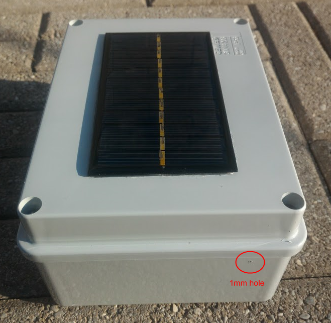
    5.5V inside
    0_1508077207132_upload-5fd5955c-e4c6-497e-9c30-92e3ec5e43aa

    Finished: the solar panel has been glued with transparent silicon for the entire perimeter
    0_1508078961144_upload-8ccf909d-3b1c-454e-9b72-69401a018193


  • Mod

    0_1507824336220_upload-2e658d71-0057-47ab-8d86-9d65134797f3

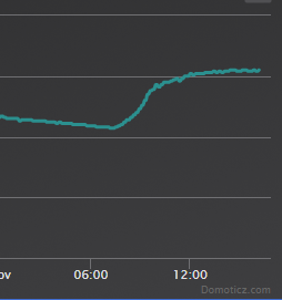
    This is today test for the 5.5V setup: put the solar panel outside this morning at 8:30; I guess at ~10am it must have got direct sunlight. Tonight I'll move the solar panel not in direct sunlight to see how it will affect charging. Btw the 8:30 voltage is after 36 hours of no charge from full caps, sleep time 10 min. The spikes were made when I was reflashed the pro mini last night with a minor SW change


  • Hero Member

    @gohan said in Supercap Solar Powered Mysensors nodes as cheap as possible:

    2.7v: using this supercap + this module, just hook up any 6v solar panel to Vin and the supercap on the Vout with a diode in between that will block any reverse current and most important will drop voltage by ~0.7v to make it suitable for the supercap.

    FWIW, I've noticed quite a variance in the peak voltage produced by various 6v solar panels, even within the same model! I've had some that go as high as 7.5v in direct sunlight. Others never make it above 5.5v even in direct sunlight. Go figure. It's best to think of 6v as a purely nominal value.


  • Hero Member

    @gohan said in Supercap Solar Powered Mysensors nodes as cheap as possible:

    2.7v: using this supercap

    At least from what I've ready, I'm pretty sure you'll find the self discharge rate on that supercap to be very high.


  • Mod

    In fact I'll do some more tests in the next days to see how much energy it can get vertically on the side of the wall, but I think I'll be heading on the 2.7v option. Maybe the crappy quality 100F Chinese supercap has an higher discharge rate, but after 3 days it is still at 1V and it has been sending 4 values every 10 minutes, so in my opinion it is a very reasonable result. In addition I'm not very convinced about the 5.5v supercaps since they are just 2 2.7v caps glued together, without any balancing, so for something that doesn't discharge to zero on a regular basis it will inevitably kill one of the 2 caps. Not to mention how much easier it is to handle a single big cap instead of soldering a bunch on some sort of pcb.

    My biggest problem now it is more related in understanding why the voltage value I get from the A0 through the voltage divider is off +/- 0.3~0.5v. I checked with the multimeter and with a voltage divider calculator and I do get values within a very small error (resistors tolerances). For example on the 2.7v caps I'm reading 1V on multimeter and arduino reports 0.7v, while on the 5.5v caps I'm getting almost 0.5v more. I'm not sure what to look for. The code was from an example of @sundberg84 . Since on the 2.7v I'm running it on a steady 3.3v source (booster), maybe I could read the voltage directly from the A0 pin without voltage divider, or is it gonna kill the arduino?


  • Hero Member

    @gohan said in Supercap Solar Powered Mysensors nodes as cheap as possible:

    My biggest problem now it is more related in understanding why the voltage value I get from the A0 through the voltage divider is off +/- 0.3~0.5v. I checked with the multimeter and with a voltage divider calculator and I do get values within a very small error (resistors tolerances). For example on the 2.7v caps I'm reading 1V on multimeter and arduino reports 0.7v, while on the 5.5v caps I'm getting almost 0.5v more. I'm not sure what to look for. The code was from an example of @sundberg84 . Since on the 2.7v I'm running it on a steady 3.3v source (booster), maybe I could read the voltage directly from the A0 pin without voltage divider, or is it gonna kill the arduino?

    IIRC, you shouldn't try to read a voltage that's higher than around 0.3v (or was it 0.6v?) more than VCC. Either way, if VCC is 3.3v, then 5.5 is well outside that range.


  • Mod

    I'm just talking about the 2.7v option. Ofc I can't read 5.5v directly


  • Hero Member

    Since you're assuming access to direct sunlight, you can tolerate a lot of inefficiencies because of the overabundance of available energy compared to what most sensor nodes require. I remember one guy posted who had a similar 6v solar panel outdoors, and IIRC he said his 10F supercap was already fully recharged just from the daylight before sunrise. i.e. it's bright outside. So, even if your cheap 100F supercaps lose most of what they collect through high self discharge, but they collect a much larger amount all day long because of their higher capacity, maybe you come out ahead. Seems like a worthwhile experiment. Glad you're doing it.


  • Mod

    0_1507838915207_upload-5d845602-b757-44da-8611-265a98133b75
    Here is the graph of the voltage: the measurements started ok at ~2.6V but now it is showing 0.66V while I read 0.936V on multimeter I wonder what it may be. My knowledge in electronics is quite poor 😅


  • Hero Member

    @gohan said in Supercap Solar Powered Mysensors nodes as cheap as possible:

    I wonder what it may be.

    I would guess the capacitor has a high internal resistance. Your multimeter doesn't see it unless the capacitor is under load. But your arduino is a load, so it sees it.


  • Mod

    Actually it should be reading the voltage from the 0.1uF cap that is on the voltage divider of the Easy PCB; would it make sense to increase capacitance? I have a bunch of 10uF ceramics


  • Hero Member

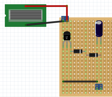
    Maybe a schematic of your setup would help the readers of your thread make informed comments. Otherwise, it starts to become 20 questions, if you know what I mean. People on this forum love to look at schematics.


  • Mod


  • Hero Member

    @gohan
    Well, if 0.1uf is normally sufficient, why wouldn't it be in your case?

    There's an easy way to test my hypothesis: why don't you try powering your setup from some fresh batteries (or a high quality supercap if you have one) and see if there's still the voltage discrepancy? If not, then it's the ESR of your cheap supercap. If it's still there, then maybe you just need to calibrate?


  • Mod

    Maybe in the WE I'll try the full range with the power supply and see, because towards the top end the values are pretty close, less than 0.1V apart


  • Mod

    I have uploaded 2 pictures of the solar powered 5.5V node


  • Hero Member

    @gohan said in Supercap Solar Powered Mysensors nodes as cheap as possible:

    I have uploaded 2 pictures of the solar powered 5.5V node

    Uploaded to where? I don't see anything. Nevermind, I see it now at the beginning of the thread.


  • Mod

    I'm currently testing the single 100F cap but it seems the buck boost is barely able to charge the supercap in direct sunlight, while the solar panel connected directly to the 5.5v supercaps was working much better. I'll have to try with a normal buck converter as it seems now the boost mode is making the solar panel working on a voltage too low that doesn't produce much power.


  • Mod

    I replaced the buck-boost module with a simple buck converter and it seems to work much better since the operating voltage is from 4.5V to 23V. As you can see from the below picture, the buck-boost barely charged the cap while in direct sunlight while the buck converter was able to charge the cap in a short time even with a cloudy day.
    0_1508680267955_upload-2fd7efbf-abd4-4b4b-ac7a-58c00e532370
    I am also very happy since I set the output voltage to 2.62V on the buck converter and I actually get 2.62V reported by the arduino.
    I also forgot to say that I am using a booster like showed in @sundberg84 project link text


  • Hero Member

    @gohan I suspect it's "working" because the voltage on your boost converter is higher than 2.62v from the solar panel anyway at the time that it's charging. Even on a cloudy day, it's not hard to get more than 2.6v on a 6v solar panel.


  • Mod

    The booster is only from the supercap to the node to keep a steady 3.3v. The solar panel if feeding the buck converter directly so it will start charging when panel is providing around 4,5v. It is a double conversion, I know, but efficiency is not the goal.


  • Mod

    I guess I might have overlooked the backward discharge of the buck converter.... It drained the supercap in 4 hours while it should have lasted 3 days. I need to put a diode in place 😅

    0_1508706780475_upload-be076a5d-9be1-4db6-a135-f618726bbc36


  • Mod

    Interesting... The node is still dead... I guess there is big flaw in the setup or the buck converter is dead due to the reverse current flow from supercapacitor


  • Mod

    Schottky diode to the rescue: the buck converter had a 1.5 mA drain. No wonder it didn't last long. After I put a schottky on the input now I get no drain 💪


  • Mod

    0_1508947582961_upload-fa827db0-bb57-447e-891c-da5819e0ab6e
    Now voltage stays between 2 and 2.4V (it should be 2.62V but I need to adjust the buck converter and add 0.2V as they are lost though the diode now). I don't understand why the voltage is so unstable now during discharge hours


  • Hero Member

    @gohan It suggests your boost converter is mostly failing to boost whatever is in the cap to the target voltage.


  • Mod

    I am measuring the supercap voltage before the booster like it was a 2xAA rechargeable batteries. If you look at previous graphs it was much smoother when the diode was not in place


  • Hi guys.
    Im I wrong if I say that both @gohan and @NeverDie discuss a lot of solar/supercap in multipe threads?
    Have some of you come to an conclution?
    Wich supercap is best(good enough)?
    Wich solarpanel the best?
    This is very interesting but im an curious what is the optimal setup?


  • Hero Member

    @xydix In what sense do you mean optimal? I think what separates our approaches is that gohan wants to buy readymade parts off aliexpress and, if possible, connect them with dupont wires. So, if that rings true for you, then you will probably find his approach more optimal.


  • @NeverDie Doesn't matter for me. I have seen your boards on openhardware for solar panels. Interesting.
    In many cases an custom PCB get pretty expensive if you just want 1 or 2 board because buy all components required, these are often is selled in 10 pcs or more.
    In my case, I want something that works, then if i can get away with just an LDO on an protoboard im fine with that.
    I try to build as cheap nodes as possible.
    Then if i can find cheap stuff in aliexpress that is doing the job, thats fine.
    Have you had any good results useing solar panel indoors?


  • Hero Member

    @xydix said in Supercap Solar Powered Mysensors nodes as cheap as possible:

    Have you had any good results useing solar panel indoors?

    Definitely yes. A typical $1 6v solar panel together with an LDO and diode works fine. At least for me. Gohan is exploring something altogether different, and I'd rather not derail his thread. So, if you want more detail, just read the thread I wrote previously.


  • Mod

    I'll let go until Saturday, then I'll do the voltage adjustment and try to discharge the supercap and see if is is able to recover from that condition. If it doesn't I'll need to find a piece of hardware that will have to hold the booster from switching on until a minimum voltage is reached and also add some dynamic sleep time that increases as the voltage decreases below certain levels


  • Hero Member

    @xydix said in Supercap Solar Powered Mysensors nodes as cheap as possible:

    @NeverDie Doesn't matter for me. I have seen your boards on openhardware for solar panels. Interesting.
    In many cases an custom PCB get pretty expensive if you just want 1 or 2 board because buy all components required, these are often is selled in 10 pcs or more.
    In my case, I want something that works, then if i can get away with just an LDO on an protoboard im fine with that.
    I try to build as cheap nodes as possible.
    Then if i can find cheap stuff in aliexpress that is doing the job, thats fine.

    If you want the barest minimum of parts, I've also done it with just a solar panel, a diode, a supercap, and mcu+radio. That's it. Then the trick is to have your mcu monitor the voltage on the supercap. As the voltage approaches the limit, the MCU turns on the radio receiver to burn off extra current, so that the voltage never exceeds the supercap's limit (usually 2.7v). It works.

    Having said all that, though, I'm interested in what Gohan will come up with. I'm sure his approach will work too. 🙂


  • Mod

    The best option I think would be 2 supercaps in series and a balance circuit/overvoltage protection /sab mosfets, this way you only need the solar panel and a diode for charging. The problem still remains when the supercaps eventually drain completely


  • Mod

    I'm kind of stuck in finding any ready made product for balancing, so I'm looking at the ALD810026 sab mosfet chip and mount it on a 8soic to dip adapter. It's the closest I could get without the need to print out a pcb. What do you think?


  • Hero Member

    @gohan said in Supercap Solar Powered Mysensors nodes as cheap as possible:

    ALD810026

    I haven't tried to do balancing, so you're guess is probably better than mine. The guy with the swiss accent had a circuit for it. Your solution sounds better than his though because his only worked while charging to maximum charge whereas yours maybe balances after-the-fact and/or to less charges as well?


  • Mod

    Yes, he used those pcbs from aliexpress that do overvoltage protection, but those are sized for much bigger caps and wouldn't fit much into small boxes. For what I could understand the sab mosfets work while the supercap discharges to keep voltage even across them, so you have to be careful not to apply a higher voltage than the maximum combined of the caps in series. If I could find a way to make a overvoltage protection with some simple components I'd be fine with it.


  • Hero Member

    Not long ago someone (was it you?) posted a link to a youtube video where some guy had a charge balancing circuit that wasted very little power, IIRC. He's probably selling it now. Maybe you could just buy one of those?


  • Mod

    exactly, it was me and it was about these sab mosfets


  • Mod

    I maybe up to something: I used a MCP1700 ldo and on Vout a diode + a schottky in series to drop the voltage ( could have used just the diode, but the Vout was 2.7x volts so for supercap longevity I added the schottky to have a safe margin) and it is charging even with panel pointed away from the sun. I'll see how it goes tomorrow, but I am pretty happy with the results so far. If it works I think i can't go cheaper then a LDO + 2 diodes ✌


  • Mod

    It started charging at around 7:30am: it is placed on an eastern wall in vertical position with practically no direct sunlight. It takes a while to stabilize around 2.55V but overall it looks reasonable for the cost of all the power circuit.

    0_1509635630373_upload-5a2288c5-2308-4125-ba3e-6d83cb94fa71


  • Hero Member

    What is the cost? Also, it's not clear to me how much usable charge you're getting.


  • Mod

    1.5€ for solar panel, 1.7€ for 100F supercap, 1€ for booster and some cents for MCP1700, diodes and a small PCB. A fully charged supercap gives 3 days of working time, with send every 10 minutes of temp. hum, TX rssi, RX RSSI, battery voltage and battery percentage


  • Hero Member

    Sounds sorta roughly like the kind of circuit used in solar garden lamps, except you've replaced the typical rechargeable battery with a supercap and are boosting to a higher voltage than they typically do. I wonder whether any of them do boost to the same voltage that you're targeting? Perhaps the brighter ones, for example? Those solar garden lights typically have a single, inexpensive integrated circuit that does it all.


  • Mod

    the booster is plugged in the Easy PCB and it is used to power arduino and sensor


  • Hero Member

    @gohan said in Supercap Solar Powered Mysensors nodes as cheap as possible:

    the booster is plugged in the Easy PCB and it is used to power arduino and sensor

    By "plugged in," do you mean like in your earlier photo?
    alt text


  • Mod

    nope, that was the 5.5v supercap version. I mean plugged in in the socket next to the green screw terminal. Of course the buck boost module now it is not used. I have to put the new photo I know.


  • Hero Member

    Since you're not posting schematics, maybe it's time for a new photo....


  • Mod

    I need to learn how to make schematics 😅


  • Mod

    0_1509643234861_upload-e0f0eada-447b-47c3-9d6d-500457d53ed2

    Does it make sense? The output terminals go to the Easy Pcb green screw terminals .


  • Hero Member

    @gohan said in Supercap Solar Powered Mysensors nodes as cheap as possible:

    Does it make sense?

    I suppose. Why the two diodes again instead of just the one?


  • Mod

    Because only one was not dropping enough voltage to have a safe margin, the schottky is giving that extra 0.2v


  • Hero Member

    You'll have a very long charge tail with the diode(s) in that position.


  • Mod

    Do you mean it will take long time to fully charge?


  • Hero Member

    @gohan Yes.


  • Mod

    It took about 5 hours to charge and it wasn't in direct sunlight, I'm still happy with the results given I'm using general purpose parts I already had around and no sophisticated charge controllers (and no particular knowledge about electronics 😅)


  • Hero Member


  • Mod

    0_1509815907001_upload-9b8d0c02-2431-40e8-a5e2-a8116c85246a

    Today was overcast all day so it took about 3 hours longer (until 3pm) to fully charge but overall it looks like a nice graph for the last 3 days.


  • Mod

    0_1510134605001_upload-fe574220-a002-4e36-bb4f-a895f54f1db9
    2 days of rain and it can't charge, luckily it has more than 3 days of running time without charge. Being not in direct sunlight (vertically positioned on a wall just below roof) it has some drawbacks, but today it is catching up


  • Hero Member

    The overcast days are where the two diodes are burning you.


  • Mod

    if it is overcast it is not that dramatic as it still charges, it is the rainy day that is bad. I know that a more efficient and specific charging circuit would work better even at lower light/voltages, but still this is working fine as it recovered to 2.4V within 3 hours and 3 more to reach 2.5V. Unless I get 4 days or rain I should be fine but in the event of 4 rainy days I think I would be more worried about other things 😄


  • Mod

    0_1511358675325_upload-4799b991-916e-4052-9fd2-b421052a9d44

    That is looking great so far (the spike was a reboot after I installed the SMA antenna)


  • Hero Member

    Since your goal was "as cheap as possible," what was your final tally on how much it cost? It would be good to know just how cheap is possible.


  • Mod

    @gohan said in Supercap Solar Powered Mysensors nodes as cheap as possible:

    1.5€ for solar panel, 1.7€ for 100F supercap, 1€ for booster and some cents for MCP1700, diodes and a small PCB. A fully charged supercap gives 3 days of working time, with send every 10 minutes of temp. hum, TX rssi, RX RSSI, battery voltage and battery percentage

    I already wrote it 3 weeks ago. 😄


  • Hero Member

    So, something like $4 then I guess at today's exchange rate.

    @gohan said in Supercap Solar Powered Mysensors nodes as cheap as possible:

    .5€ for solar panel, 1.7€ for 100F supercap, 1€ for booster and some cents for MCP1700, diodes and a small PCB.


  • Mod

    yes 5$ range, of course you need to add the other costs like box, the node itself and everything you need to have the node working outdoor


  • Hero Member

    I wonder if you might do better with the cheaper 10F chinese supercaps. Obviously they hold less initially, but the question boils down to whether they end up holding more in the end if only because they're losing charge at a much slower rate. I don't know what the answer will be. It's really an empirical question.


  • Mod

    Of course a better quality one would hold the charge better, but at what cost? Would it be really beneficial also from a cost perspective? Maybe, I don't know... It could be that a couple of good quality 10F caps are fine and that you could get away also with a smaller/cheaper solar panel, it's all a matter of trying 😀


  • Mod

    I think I found a major flaw in the design: if the supercap voltage drops below 0.8V the booster is not able to work properly and instead of shutting off it starts drawing current until the supercap is empty. I did some startup tests at 0.8V and I saw current up to 140mA, much more than the solar panel can provide. I would need to reach around 1V on the supercap in order to have a safe margin to have a complete startup cycle. At this time of the year the daylight is getting shorter every day and clouds are making even more difficult to get a proper charge. I haven't done many changes so far because I wanted to see how it behaved in the worst conditions that we get during winter. Now the next steps are: adding some code to make sleep time increase as the supercap voltage decreases and making a board with the 3 supercaps I have in order to avoid as much as possible the voltage to drop below the 0.8V.


  • Hero Member

    Three supercaps? Sounds like you're leaving the zone of "as cheap as possible." I'd also be leary of a solar design where falling below "x" voltage leaves the system in a state it can't recover from without human intervention. Murphy's Law. Stuff happens.


  • Mod

    Well, I said 3 because I have 3 and I paid 3.35€ for 2, so it is not that expensive. The problem is that I would need to add something that would wait for the voltage to reach 1V after it has dropped below 0.8V before giving power to the booster: that is where a charge controller may come handy. Unfortunately I have no sufficient knowledge on how to solve this problem, so for now the code and 3 supercaps would have to do 😄


  • Hero Member

    @gohan You can solve that using a voltage detector. 0.2v hysteresis would not be uncommon. So, it would cut the current to your boost converter when the voltage drops below 0.8v, and it wouldn't allow it to come back on again until your supercap voltage reaches 1.0v.


  • Mod

    do you have an example I could take a look? I never used them


  • Hero Member

    @gohan Not really, but the datasheets for voltage detector chips would have example circuits.


  • Hero Member

    They're commonly used in brownout detectors and also circuits that do automatic resets if the voltage drops below a particular threshold. Not sure whether Aliexpress has premade circuits you can just buy, which seems to be your preference. Maybe. I haven't looked for that.


  • Hero Member

    @gohan said in Supercap Solar Powered Mysensors nodes as cheap as possible:

    do you have an example I could take a look? I never used them

    I'm just remembering now that I used a voltage detector in this project, where in the comments I gave you a detailed walk-thru explanation for how it worked:
    https://www.openhardware.io/view/396/Simple-Solar-Supercap-Charger#tabs-instructions
    The design files include a schematic.


  • Mod

    I believe I found another problem: the discharge I am seeing in the supercaps, I am suspecting it is due to the self discharge as it is not affected by the sleep time and the adding of the second supercapacitor.
    As usual the Chinese stuff it is just worth the money you pay for it.


  • Hero Member

    @gohan What exactly is it that you're noticing?


  • Mod

    Looking at how quickly the voltage drops over time, I'm seeing no big difference between sending data every 10/30/60 minutes and even adding a second supercapacitor so I'm assuming they are just junk
    I'm seriously considering ditching the supercaps and go with a LiFePo4 battery and leaving just the mcp1700 to keep the battery at 3.3v


  • Hero Member

    @gohan Maybe before giving up entirely, perhaps you want to try a quality supercap in place of the shoddy one?


  • Mod

    Do you have any suggestion on something of decent quality and not too high price? I mean something of at least 100F but that doesn't cost like 10$


  • Mod

    @gohan do you really need 100F? How much energy does your node consume? Maybe it is easier to get the energy consumption down than to find a cheap huge capacitor wih low self-discharge?


  • Mod

    Well it probably doesn't need that much, but I plan to add more sensors and I need to compensate for the winter days when it's cloudy and the daylight is shorter. Of course I could expose the solar panel to direct sunlight to optimize the charging but it would be exposed to harsher weather conditions and the sun will cause the temperature reading to be higher.


  • Hero Member

    @gohan said in Supercap Solar Powered Mysensors nodes as cheap as possible:

    Do you have any suggestion on something of decent quality and not too high price? I mean something of at least 100F but that doesn't cost like 10$

    https://www.digikey.com/products/en/capacitors/electric-double-layer-capacitors-edlc-supercapacitors/61?k=avx+supercap&k=&pkeyword=avx+supercap&pv2049=u100F&mnonly=0&ColumnSort=0&page=1&quantity=0&ptm=0&fid=0&pageSize=25

    AVX is a good brand. At least worth a shot to test your idea. If it doesn't meet your expectations, then it's not the supercap's fault. If it turns out to be overkill, you can downgrade from there. Or just start with the higheswt capacity AVX supercap that you think is affordable and make your give-up decision after first testing with that.


  • Hero Member

    @mfalkvidd said in Supercap Solar Powered Mysensors nodes as cheap as possible:

    @gohan do you really need 100F? How much energy does your node consume? Maybe it is easier to get the energy consumption down than to find a cheap huge capacitor wih low self-discharge?

    I agree, but I think he just wants to quickly test his proof-of-concept first without thinking about it too hard. Kinda a first-fit rather than best-fit search pattern. We've all done it, I'm sure.


  • Mod

    @neverdie 8$ it is not bad but still 6x the initial price I was thinking. Also 8$ is the cost of 3 or 4 LiFePo4 AA batteries that are less temperature sensitive than lipo but can still hold a lot more energy than a supercapacitor and have the right 3.3v working voltage avoiding the need for a voltage regulator/booster . I'll think about it


  • Hero Member

    @neverdie said in Supercap Solar Powered Mysensors nodes as cheap as possible:

    Or just start with the highest capacity AVX supercap that you think is affordable


  • Mod

    I always like to stay on the safe side and plan ahead. Now I need to find out quickly if the solar panel is actually able to provide enough power to keep the node running even with short daylight ( I am thinking about using the LiFePO4 battery charged at 3.1V and see if it can reach the 3.3V or if it drops below 3V); meanwhile I'll try to do a runtime test on the supercaps and try to see how long I can power a node without sleep and make an estimate for a target capacity of a good quality supercap


  • Mod

    The LiFePO4 battery setup was unable to charge the battery (maybe because I didn't study how to charge those batteries). I am now back to the 5V supercaps but with the HW radio to see how it works and I noticed the TX power dropped from 40% to 0% so the power amplifier is actually doing its job


  • Mod

    Also the buck/boost module has some low voltage issues when voltage drops below 1.4V it start drawing 130/140mA and I needed to increase voltage to 1.7V (where it was drawing 240mA) before it started to supply the correct voltage for the node to boot and have the current back to a normal 20/40mA.
    I need to find a solution for recovering the node after the booster goes crazy and that would require for sure using a voltage detector like @NeverDie suggested but that is going to require making a custom PCB with integrated booster for the 3.3v output and the supercap charger mentioned earlier.
    Is anybody willing to help? 😅


  • Mod

    Ok, after almost a year 3 out of 5 5.5v supercaps started leaking... Rip


  • @gohan that's a pity. Do you know what the root cause could be? Temperature? Charging cycles? Bad part quality?


  • Hero Member

    Andreas Spiess did a whole video on how to properly charge supercaps in series. Gohan's supercaps were just soldered together without those protections to get their 5.5v rating. Maybe it was that. Or, since it was outdoors, maybe corrosion got to them.... It would be interesting to hear what Gohan's post-mortem reveals. As Edison would say, Gohan learned a new way of how not to do it. That still leaves a lot of ways that it could be done though.


  • Mod

    No idea really, the box was sealed. I suspect they might have gotten unbalanced. About charge cycles I don't think they were a problem since they probably had less than 400 (1 cycle a day). They were cheap Chinese parts, so poor quality for sure given the self discharge rate they had. Given the cost of a LiFePO4 battery compared to supercaps, I think I'm going to take the battery route and ditch the whole solar power. I have an identical node running on a single AA LiFePO4 and in 8 months it barely discharged even if it is sending 4 values every 10 minutes


  • Hero Member

    I've forgotten, but didyou do any protection circuit for your supercaps to keep each one from overcharging? Julien Ilett tested some and found that not all of Chinee circuits stopped the charging at 2.7v, but instead allowed them to go to 2.8 or 2.9v instead:
    https://www.youtube.com/watch?v=r7M6Pb2roLs&t=180s
    So, maybe that's what happened to the yours that leaked.


  • Mod

    I couldn't because they are packed together, but it was something I was expecting anyway. I had them completely discharged every now and then when the arduino went crazy and drained them out.


  • Mod

    Small update after some time running on 2 100F supercaps in parallel

    0_1538559724740_25ea6c6c-ab32-4422-93a0-a8d6875d0972-image.png

    Voltage seems consistent over time

    0_1538559840091_b6c991f5-00ef-4008-97d6-13952e2fd45f-image.png

    Here you can see the transition from the 5.5v supercaps to the normal ones, the odd thing is that it seems the supercaps took a few days to accept higher charge voltage


  • I may misunderstand how they work, but I've had the idea that (super)caps are better in short term high current situations. Like regenerative brakes for robot lawnmowers, not slow drain low power devices. It sounds to me like the life boat is the lifepo4 batteries. I'm all for experiments, so please dont stop, but unless the environmental conditions are intolerable for the batteries, I'd say you found your answer.


Log in to reply
 

Suggested Topics

  • 8
  • 7
  • 1
  • 2
  • 1
  • 5

0
Online

11.4k
Users

11.1k
Topics

112.7k
Posts