nRF5 action!


  • Hero Member

    Good news! Switching over to the RC oscillator totally fixed the problem. Both the Fanstel BT832 and BT832X now receive just fine. 🙂


  • Hero Member

    In fact, both the Fanstel BT832 and the BT832X (with no LNA turned on) have much better receive range than an Ebyte module. They are head and shoulders better. In turn the BT832X (again, even with no LNA turned on) has a noticeably better receive range than the BT832.

    So, at this point, I'm sold on the Fanstel modules for the most common uses. The Fanstel modules also have a smaller footprint than the Ebyte modules. The Ebyte modules might be better for those cases where you need a lot of easily accessible pins to do something, but that's about it I think.


  • Hardware Contributor

    @NeverDie said in nRF5 Bluetooth action!:

    In fact, both the Fanstel BT832 and the BT832X (with no LNA turned on) have much better receive range than an Ebyte module. They are head and shoulders better. In turn the BT832X (again, even with no LNA turned on) has a noticeably better receive range than the BT832.

    So, at this point, I'm sold on the Fanstel modules for the most common uses. The Fanstel modules also have a smaller footprint than the Ebyte modules. The Ebyte modules might be better for those cases where you need a lot of easily accessible pins to do something, but that's about it I think.

    Now we need to convince Fanstel to find another shipping method outside the US 😄


  • @NeverDie it looks like we found an ideal gateway.
    What about the code they provide to activate PA+LNA?
    Can it be used in mysensors?


  • Hero Member

    I tried out the sub-dime sized BC832 on a quick port of the BC832X breakout board:
    0_1509402087595_bc832.jpg

    What I'm finding is that the Rx range for the BC832 is about the same as for the Ebyte nRF52832 module: I'm hard pressed to tell which is better than the other. The BC832 is nonetheless impressive, given how small its antenna is relative to the Ebyte antenna.


  • Hero Member

    @Toyman said in nRF5 Bluetooth action!:

    it looks like we found an ideal gateway.

    Agreed. 🙂

    @Toyman said in nRF5 Bluetooth action!:

    What about the code they provide to activate PA+LNA?

    I only extracted the needed info from their code to make it work. It works just fine with mysensors. For instance, here's mysensors code to activate the PA:

    #define PA_PIN 17
    #define CPS_PIN 6
    #define LNA_PIN 19 
    
      myNrf5_pinMode(CPS_PIN,OUTPUT_H0H1);
      digitalWrite(CPS_PIN,HIGH);  //disable.  Active LOW
      //while (!(digitalRead(CPS_PIN)==HIGH)) {} //wait until confirmed
       
      myNrf5_pinMode(LNA_PIN,OUTPUT_H0H1);
      digitalWrite(PA_PIN,LOW);  //disable.  active HIGH
      //while (!(digitalRead(LNA_PIN)==LOW)) {} //wait until confirmed
      
      myNrf5_pinMode(PA_PIN,OUTPUT_H0H1);  
      digitalWrite(PA_PIN,HIGH);  //enable.  active HIGH
      //while (!(digitalRead(PA_PIN)==HIGH)) {} //wait until confirmed
    
      //myNrf5_pinMode(CPS_PIN,OUTPUT_H0H1);  
      digitalWrite(CPS_PIN,LOW);  //enable.  active LOW
      //while (!(digitalRead(CPS_PIN)==LOW)) {} //wait until confirmed
    

    I've tested it, and it works. From my testing it appears that the pins are write-only (which is why the while loops are now commented out).


  • @Nca78 How about sending a email to the company and ask if there is a distributor / Rep in your area?
    Dr. Yuan Fan
    Fanstel Corp.
    Trusted Name Since 1990
    7466 E. Monte Cristo Ave., Scottsdale AZ 85260 USA
    Tel. 1480-948-4928 x101;
    email: yfan@fanstel.com http://www.fanstel.com


  • Hero Member


  • Hero Member

    @Toyman Have you received your Fanstels yet? I'd like to compare notes with someone on the LNA part of it.


  • @NeverDie I haven't ordered yet. Waiting for my paycheck.


  • Hero Member

    When you combine my BT832XE gateway with the LNA on this external "booster," the result is really great reception range, even at 2Mbps:
    0_1509558101829_awesome.jpg
    I think this combo will be hard to beat. In fact, I can receive even from nRF24L01's that are far away (further away than a nRF24L01 with PA+LNA can receive). 🙂


  • Well my NRF51822 has been running 25days approx sending every 60secs on a cr2032.
    No signs of problems yet.
    0_1509561715247_upload-e21e5fcc-113b-4d47-bd54-7d7d89841bf9


  • Hero Member

    @rmtucker I don't recall whether you already have, but would you mind posting a photo of your node?


  • @NeverDie
    Its just the waveshare ble400 board but i have cut one of the tracks to prevent the residual drain from the on board regulator.
    And i have an external cr2032 battery holder feeding it.
    I would love to make a small pcb for the NRF core to plug in to instead of the big motherboard as below, but i failed dismally at the design side of things.

    0_1509571898531_upload-00d6665f-f065-4ed7-927d-2a5e27224fc6


  • Hero Member

    @rmtucker said in nRF5 Bluetooth action!:

    I would love to make a small pcb for the NRF core to plug in to instead of the big motherboard as below

    Here you go: https://www.openhardware.io/view/510/Button-cell-Temperature-Humidity-sensor#tabs-bom

    This should be even smaller and less expensive than what you wished for. I made it for the Si7021 because I had some extras laying around. The BME280 would also be a good choice.


  • @NeverDie
    That would be perfect but i would have to order everything from china.
    Well maybe not the led and resistor.
    I also prefer the si7021 also it has far less consumption and quite accurate.


  • Hero Member

    @rmtucker said in nRF5 Bluetooth action!:

    I also prefer the si7021 also it has far less consumption and quite accurate

    As long as the humidity is less than 80%. Otherwise, you need to turn on its "heater" to avoid permanently ruining its humidity accuracy.


  • Hardware Contributor

    @NeverDie it's not that quick, it happened only to the one I put in bathroom with very high humidity for a long time.
    Other sensors reached over 90% humidity sometimes and spent many days in the 75-85 range but just a nightly use of aircon seems to have maintained their hability to measure humidity.
    So my feeling is unless you are in a very humid environment you should have no problem with the si7021.

    I'm in a tropical country and problem happened during rainy season, >80% humidity at 30°C makes a lot of humity in the air, I don't think you get close to that level in European countries or most of the US.


  • Hero Member

    @Nca78 I'm just taking what the datasheet says at face value. In practical terms, I think it's fairly rare to see >80% humidity in an indoor "conditioned space" (well, maybe a bathroom is an exception to that sweeping generality) but outdoors it happens by definition anytime the air temperature approaches the dew point. That certainly does occur in quite a lot of geographies.

    So, for that reason, I think of the si7021 as more of an indoor TH sensor. From what I can tell, the BME280 doesn't have this issue, so it would therefore seem to be a good choice for outdoors.

    Of course, the si7021 sensor modules are made in Asia, and if it's tropical asia (Thailand for instance?), it may have already been exposed to high humidity. So, that's a bit of an unknown factor hanging in the background.

    Anyhow, thanks for the additional insight that maybe the si7021 really needs to soak in high humidity for a long time before it gets ruined. Otherwise, it can spring back from brief exposures. I certainly hope that's the case. Running its heater does consume a significant amount of current.


  • Hero Member

    It turns out that on the nRF52832, pins 9 and 10 are assigned to NFC by default. The following code allows them to behave "almost" like regular GPIO pins:

      //Make pins 9 and 10 usable as GPIO pins.
      NRF_NFCT->TASKS_DISABLE=1;  //disable NFC
      NRF_NVMC->CONFIG=1;  // Write enable the UICR
      NRF_UICR->NFCPINS=0; //Make pins 9 and 10 usable as GPIO pins.
      NRF_NVMC->CONFIG=0;  // Put the UICR back into read-only mode.
    

    Well, good enough for a blink demo anyway.


  • Hero Member

    Is there some particular trick to reading the built-in temperature sensor? I've tried it a number of ways, but after doing

    NRF_TEMP->TASKS_START
    

    I can never get NRF_TEMP->DATARDY to return true, no matter how long I wait. If I just try reading NRF_TEMP->TEMP anyway, it always returns zero.

    [Edit: Nevermind. The answer was right in front of me. It obviously should have been:

    NRF_TEMP->TASKS_START=1;
    

    Because the PPI uses the former syntax, and the regular code uses the later syntax for the same thing, I sometimes interchange the syntax by mistake.

    Anyhow, problem solved. 🙂


  • @NeverDie said in nRF5 Bluetooth action!:

    BT832XE

    What booster is it?


  • Hero Member

    @NeverDie said in nRF5 Bluetooth action!:

    @rmtucker said in nRF5 Bluetooth action!:

    I would love to make a small pcb for the NRF core to plug in to instead of the big motherboard as below

    Here you go: https://www.openhardware.io/view/510/Button-cell-Temperature-Humidity-sensor#tabs-bom

    This should be even smaller and less expensive than what you wished for. I made it for the Si7021 because I had some extras laying around. The BME280 would also be a good choice.

    I'm realizing now that I can get a decent temperature reading from just the nRF5x chip itself. With calibration it should get even better.


  • Hero Member

    Today I finally received the PTR9618PA that I ordered a while back:
    0_1510110556809_ptr1.jpg
    0_1510110572062_ptr2.jpg

    Like the Fanstel modules, it lacks a 32.768Khz crystal oscillator. Also, as you can see from the second photo, the PA/LNA chip is the 2401C: http://www.skyworksinc.com/Product/3213/RFX2401C


  • @NeverDie said in nRF5 Bluetooth action!:

    @NeverDie said in nRF5 Bluetooth action!:

    I'm realizing now that I can get a decent temperature reading from just the nRF5x chip itself. With calibration it should get even better.

    I used the internal temperature in the past but i can not remember how i did it?
    Do you have some example code to remind me?


  • Hero Member

    @rmtucker said in nRF5 Bluetooth action!:

    Do you have some example code to remind me?

    /*
     * This example sketch shows how you can manage the nRF5 pin mapping as part of your code.
     * You can use the method for any nRF51822 or nRF52832 board or module.
     * 
     * Most components, like UART, SPI, Wire Bus, of the nRF5 series chips don't
     * have a fixed pin mapping. There are some pins with restrictions like analog
     * inputs, NFC or pins near the radio module. Please refer the latest
     * documentation about pin restrictions at http://infocenter.nordicsemi.com 
     * 
     * To use the custom pin mapping you have to do following steps:
     * 
     * 1. Install "arduino-nrf5" like described at
     *    https://github.com/sandeepmistry/arduino-nRF5/
     * 2. Install the "My Sensors nRF5 Boards" with the board manager like
     *    explained at https://github.com/mysensors/ArduinoBoards
     * 3. Copy the files "MyNRF5Board.cpp" and "MyNRF5Board.h" from
     *    "MyNRF5Board" example into your sketch.
     * 4. Modify pin mappings in "MyNRF5Board.cpp" and "MyNRF5Board.h" to fit
     *    your requirements.
     * 5. Select "MyNRF5Board nrf52832" or "MyNRF5Board nrf52822" as your board.
     *    Choose the correct parameters and programmer in the Tools menu.
     */
    
    // Many thanks to d00616 for this framework!
    
    //------------------------------------------------------------------------------------------------------------------------------------------------------------------------
    
    //Simple program to demonstrate that both the LED and Serial  and Temperature are working correctly on the breakout board:
    // https://www.openhardware.io/view/471/Ebyte-nRF52832-Small-Breakout-Board
    
    //Note: Compile and upload from Arduino IDE using "MyNRF5Board nRF51822" as the board and with 16K RAM, RC Oscillator, and no bootloader as the options.  
    //


    #define MY_CORE_ONLY
    
    #include <nrf.h>
    #include <MySensors.h>
    
    
    void setup() {
      hwPinMode(LED_BUILTIN,OUTPUT_D0H1);
      digitalWrite(LED_BUILTIN,HIGH);
      NRF_CLOCK->INTENSET=B11;  //enable interrupts for EVENTS_HFCLKSTARTED and  EVENTS_LFCLKSTARTED
      Serial.begin(9600);
      Serial.println();
      Serial.println("Starting...");
      NRF_CLOCK->TASKS_HFCLKSTART=1;  //start the high frequency crystal oscillator clock
      while (!(NRF_CLOCK->EVENTS_HFCLKSTARTED)) {} //wait until high frequency crystal oscillator clock is up to speed and working
    
      NRF_TEMP->TASKS_STOP;
      NRF_TEMP->EVENTS_DATARDY=0;
    
      NRF_TEMP->INTENSET=1;  //enable EVENTS_DATARDY temperature interrupt
      while (!(NRF_TEMP->INTENSET==1)) {} //wait until completed
    }
    
    uint32_t blinkCounter=0;
    uint32_t rawTemperature=0;
    float celsius=0.0;  //rawTemperature converted to Celsius
    void loop() {
      NRF_TEMP->TASKS_START=1;
      while (!(NRF_TEMP->EVENTS_DATARDY)) {} //wait until temperature measurement is complete
     
      rawTemperature=NRF_TEMP->TEMP;
      celsius=((float)rawTemperature)/4.0;
    
      Serial.print(celsius);
      Serial.println(" degrees Celsius");
        
      Serial.print(blinkCounter++);
      Serial.println(", HIGH");
      digitalWrite(LED_BUILTIN,HIGH);
      delay(500);
      Serial.print(blinkCounter++);
      Serial.println(", LOW");
      digitalWrite(LED_BUILTIN,LOW);
      delay(500);
    }
    

  • Hero Member

    I made a prototype of my CR2032 buttoncell project using the earlier small nRF51822-4 beakout board. I have it running the MySensors passive sensor code. It reports to the serial gatewaqy once every minute.
    0_1510229855666_cr2032_proto1.jpg


  • Hardware Contributor

    cool.
    you could add some clearance for the antenna, better I think for antenna radiation.


  • Hero Member

    @scalz said in nRF5 Bluetooth action!:

    you could add some clearance for the antenna, better I think for antenna radiation.

    0_1510243932750_cr2030_proto2.jpg
    0_1510243941869_cr2030_proto3.jpg

    OK, I adjusted it. How about now?


  • I dont have access to the source code now. Can someone please tell which pins are configured as Tx and Rx for serial communication ?


  • Hero Member

    @ahmedadelhosni Do you mean in general? In the general case, you can select which pins are meant for Rx and Tx using your software.


  • Yes I read this from the datasheet but I thought maybe MySensors defines some Pins for debugging.

    How can I set them ? Any ApI refrences ?


  • Hero Member

    @ahmedadelhosni said in nRF5 Bluetooth action!:

    Yes I read this from the datasheet but I thought maybe MySensors defines some Pins for debugging.

    How can I set them ? Any ApI refrences ?

    Look at the source code posted at https://www.openhardware.io/view/510/CR2032-Small-Wireless-Temperature-Humidity-Sensor#tabs-source

    It will be obvious from that.


  • Contest Winner

    @ahmedadelhosni said in nRF5 Bluetooth action!:

    Yes I read this from the datasheet but I thought maybe MySensors defines some Pins for debugging.
    How can I set them ? Any ApI refrences ?

    Most NRF5 pins are freely configurable. MySensors only uses the definition of the Arduino variant. If you are not lucky with the pins defined with the Arduino board variants, you can use the ArduinoHwNRF5 board. There are examples to redefine pins.

    This repository has the release 0.1.0 its usable and stable, but I have plans to rename the files to MyBoardNRF5 and change the g_ADigitalPinMap to the more flexible Arduino primo format in the near future. I think this is required to support NRF52840 MCUs in the future.


  • Thanks both for the guiding. I will look through them.


  • Hardware Contributor

    @NeverDie how is the battery voltage doing on your existing test node ?
    I think you should include a strong capacitor to help the battery during TX/RX sequences. It's probably less necessary on NRF5 boards, but on atmega+nrf24 a board without a 100-200µF (meaning only around half of that available with a 3V bias) capacitor has a very poor battery life.


  • Hero Member

    @Nca78 said in nRF5 Bluetooth action!:

    @NeverDie how is the battery voltage doing on your existing test node ?
    I think you should include a strong capacitor to help the battery during TX/RX sequences. It's probably less necessary on NRF5 boards, but on atmega+nrf24 a board without a 100-200µF (meaning only around half of that available with a 3V bias) capacitor has a very poor battery life.

    No real data as of yet, though I haven't noticed any problems per se. What size capacitor do you recommend?

    Here's why I was hoping I could maybe sidestep the issue:
    0_1510565830687_pulse.png
    http://data.energizer.com/pdfs/cr2032.pdf
    i.e. very short pulses might have stable voltage. I'm not sure what amount of current is assumed by that Energizer graph though.


  • Hardware Contributor

    @d00616 said in nRF5 Bluetooth action!:
    I think this is required to support NRF52840 MCUs in the future.

    Again, you've done a nice a work on ESB driver 👍
    At least we can confirm that nrf52840 works with regular variant boards, and basic MySensors features, as it was a part of an intense traffic setup yesterday.

    That's the proof MySensors is getting better week after week 🙂


  • Hardware Contributor

    @NeverDie
    I would use 100 to 200uf like said above. That's what i'm doing with all my coincell nodes too.
    This is regarding the internal resistance of coincells which is not great >5mA, especially when coincell will be more aged. So it is recommanded to increase lifetime.

    But not too strong capacitor value, else that won't be better (you don't want to waste energy, and increase internal coincell res, by charging caps, else you would need a current limiting resistor lol).

    I would not be too cheap by omitting decoupling and buffering capa, on my boards I prefer to have footprints (optional or not) because sure it can work well at the beginning but as soon as lifetime goes, it can change..


  • Hero Member

    Thank you @nca78 and @scalz . Per your suggestions, I added a 100uF ceramic cap to version 8 of the multi-sensor board:
    https://www.openhardware.io/view/510/Multi-Sensor-TempHumidity-LeakMagnetLightAccel


  • Hero Member

    Anyone tried building a bluetooth stack on the nRF5x from within the Arduino IDE? I can see how running it simultaneously with the mySensors code would be tricky, but maybe one could switch back and forth between the two? e.g. if you want to output debug text to a terminal window on your smart phone via bluetooth If so, anyone have any demo code for doing that?

    For that matter, has anyone here tried the Arduino Primo? And if so, how did it go?


  • Hardware Contributor

    @NeverDie said in nRF5 Bluetooth action!:

    Anyone tried building a bluetooth stack on the nRF5x from within the Arduino IDE? I can see how running it simultaneously with the mySensors code would be tricky, but maybe one could switch back and forth between the two?

    From what I understand this is not possible, the NRF5 Core used by @d00616 is not using the soft device to have better access to the hardware, while the Arduino IDE version is using soft device to run bluetooth stack. So you have to flash one or the other, not the two at the same time.


  • Contest Winner

    @NeverDie said in nRF5 Bluetooth action!:

    Anyone tried building a bluetooth stack on the nRF5x from within the Arduino IDE? I can see how running it simultaneously with the mySensors code would be tricky, but maybe one could switch back and forth between the two? e.g. if you want to output debug text to a terminal window on your smart phone via bluetooth If so, anyone have any demo code for doing that?

    The parts of the SDK to disable and enable the SoftDevice are not included into the arduino-nrf5 port, but on the Primo port.

    For that matter, has anyone here tried the Arduino Primo? And if so, how did it go?

    The Arduino-NVM library is not compatible. This results in a crash. My first try to use the SoftDevice API was not successful.


  • @d00616 have you looked at https://mynewt.apache.org/?


  • Hero Member

    @Toyman said in nRF5 Bluetooth action!:

    @d00616 have you looked at https://mynewt.apache.org/?

    Does it have any worthwhile demo apps running on it?


  • Contest Winner

    @Toyman said in nRF5 Bluetooth action!:

    @d00616 have you looked at https://mynewt.apache.org/

    Yes, I have seen the documentation and some parts of the source code. It's a good project. I like the concepts.


  • Hardware Contributor

    @Toyman said in nRF5 Bluetooth action!:

    @d00616 have you looked at https://mynewt.apache.org/?

    on my side, i tested it. agree with d00616, it's interesting.
    yes there are examples.


  • Hero Member

    How would you all rate the mynewt's stage of development? Pre-alpha? Or, is it already fairly well tested and production ready?


  • Hardware Contributor

    latest release is 1.2.0, it's not prealpha. for production I think, easiest is to read docs and try 😉

    Note it's an OS (which means shared resources etc..), not arduino integrated, nor mysensors compatible actually. If you want to use MySensors, you would need to port the code and check what's in use by the OS etc..

    If I would like to use a RTOS+BLE with NRF5, I would use this one.
    For other mcus, not sure, there are others nice OS.
    Hard to find one fits for all, and not very handy to have x toolchains&libraries to handle (I already have arduino, espressif, apache, TI.. OS&frameworks installed and this can be too much!). And i don't mention rpi/linux stuff..

    That depends on the project.
    But for my HA project, as MySensors targets arduino actually, and I prefer the NRF5 ESB driver than BLE for multiple reasons (security etc), it's easier to stick to arduino environment and I can use all mcus for that in Visual Studio.


  • Hero Member

    How are people here preferring to connect to their nRF5x node for programming/debugging? I had been using a 10-pin IDE boxed connector on the PCB's I was making, but I just recently tried a micro-USB OTG connector (just as a 5-pin connector, not for anything truly USB protocol related), and I find that I like it a lot. For one thing, it's a lot more compact:
    0_1511483028982_usbcon_2.jpg
    0_1511483048204_usbcon_1.jpg

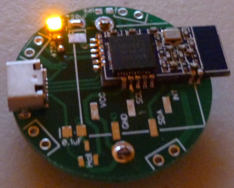
    It does require making an adapter, but once you've made it (once and done), it's easy.

    Any thoughts on this? I'm tentatively leaning toward switching over to it for everything.


  • Hero Member

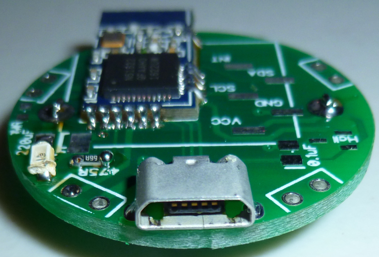
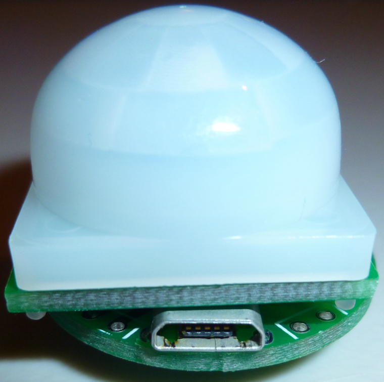
    The other cool thing is that the side access allows me to make a very compact PIR motion sensor that's still re-programmable:
    0_1511485705122_compact_PIR.jpg
    🙂


  • Hardware Contributor

    @NeverDie I think it's ok only if you keep those only for yourself, and/or make an enclosure hiding this plug.
    Because if you give to someone like a friend and an USB plug is visible one day or another they'll plug it and fry the board with 5V 🙂


  • Hero Member

    Good point. To avoid that as a potential problem then, can anyone suggest a better connector to use?


  • Hero Member

    I suppose if/when OTA updates are developed for the nRF5x's, then the issue would go away. Then you'd only need the connector when first setting it up, and then later work could be uploaded OTA. After the initial setup, one could simply sabotage the USB connector (fill it with epoxy maybe, or perhaps just cut the traces) to prevent the friend from plugging the node into an actual USB charger or the like.


  • Mod

    I'd say to make something with pogo pins if you really need it once


  • @NeverDie check out a product called "TAG-CONNECT". It is perfect for programming. It is used on the Nordic Semiconductor Beacon Reference Design.


  • Contest Winner

    @Jokgi said in nRF5 Bluetooth action!:

    @NeverDie check out a product called "TAG-CONNECT". It is perfect for programming. It is used on the Nordic Semiconductor Beacon Reference Design.

    Thank you. Here is an programmer with this connector: http://aconno.de/acnprog/
    I don't know if this is compatible to the Beacon Reference Design, but its compatible with the nRF52 boards provided by aconno.


  • @d00616 not familiar with the USB interface / tag connect. The ones I have used have the connector type that plugs onto the nRF5x-DK, uLinks, jlink lite, etc. a ten pin Micro Cortex connector to six or ten pin "pogo pin" tag-connect connector. There is also a clip that allows the connector to stay attached for debugging purposes.


  • Hero Member

    A bit off-topic perhaps, but does anyone here happen to know what kind of switch Enocean uses to transduce a button press into the electrical energy needed to send a packet? I'm guessing it's some kind of piezo switch. Can just that transducer part be purchased by itself? I'm wondering whether the same trick can be done using an nRF5...


  • I would stick with cortex 10-pin connector. Mostly because it's (a) standard (b) a cable can be made without soldering by using IDC connectors and a ribbon cable.
    The only downside is height.
    Using USB connector for sometging that's not USB is generally a bad idea as it's not foolproof


  • Is signing soft supported or not yet ?

    The personalizer sketch do not have hash define for the NRF52.


  • Contest Winner

    @ahmedadelhosni pull requests are always welcome.


  • Contest Winner

    @ahmedadelhosni said in nRF5 Bluetooth action!:

    Is signing soft supported or not yet ?
    The personalizer sketch do not have hash define for the NRF52.

    The security personalizer is working with the NRF5X. Random numbers for the Soft Signing are generated with the internal AES hardware, seeded with the hardware number generator. This allows a fast and secure nonce generation.

    At the Moment the NRF5 with Soft Signing is not at the same level like the ATSHA204, because the read back protection is not enabled. If you want to do this, you have to add some code.


  • Hero Member

    What else should I turn-off to save power during sleep?

    Presently, I turn-off these things: the radio, NFC, the high frequency clock, and uarte, Meanwhile, the low frequency clock is working.

    Presently getting a sleep current drain of apprxoimately 2.8 microamps.


  • Hardware Contributor

    @NeverDie said in nRF5 Bluetooth action!:

    What else should I turn-off to save power during sleep?

    Presently, I turn-off these things: the radio, NFC, the high frequency clock, and uarte, Meanwhile, the low frequency clock is working.

    Presently getting a sleep current drain of apprxoimately 2.8 microamps.

    Which chip are you talking about ?


  • Hero Member

    nRF52832. I'm guessing the same will apply to the nRF51822, except for the NFC (which the nRF51822 doesn't have).


  • Hero Member

    I should probably add that the 2.8ua is with the RTC and LPCOMP running. So, maybe it's already as low as it can go, I don't know. Just wondering if there are any other obvious suspects I should try turning off. I'll try i2C and SPI to see if it makes a difference... Not sure, but maybe SPI gets initialized through the header file without my even being aware of it.


  • Hero Member

    Well, it could be within the bounds of measurement error, but it appears that dropping I2c and SPI has reduced the drain to 2.6ua.


  • Contest Winner

    @NeverDie said in nRF5 Bluetooth action!:

    Well, it could be within the bounds of measurement error, but it appears that dropping I2c and SPI has reduced the drain to 2.6ua.

    Is I2C or SPI used somewhere in your code?


  • Hero Member

    @d00616 said in nRF5 Bluetooth action!:

    @NeverDie said in nRF5 Bluetooth action!:

    Well, it could be within the bounds of measurement error, but it appears that dropping I2c and SPI has reduced the drain to 2.6ua.

    Is I2C or SPI used somewhere in your code?

    Not in the current test code that I'm running.


  • Contest Winner

    @NeverDie said in nRF5 Bluetooth action!:

    Not in the current test code that I'm running.

    Interesting. The SPI is rated with <1µA idle current. TWI has no idle current in the datasheet.


  • Hero Member

    @d00616 Well, I suppose that's consistent with what I'm seeing, isn't it? i.e. not much effect.


  • Hero Member

    So far, UARTE is the biggest offender. Turning off and disabling that saves a lot of current.


  • Hero Member

    So, here is code which works! Many thanks to @d00616 and others for their helpful comments above.

    To keep from distracting, I stripped out the radio code, but you can easily insert your favorite brand of that.

    Basically, the sketch blinks an LED very briefly once every 5 seconds. Between blinks, it sleeps. However, if a leak is detected (which is equivalent to a button push), it wakes up immediately and blinks a lot. It runs on both nRF52832 and nRF51822. The sleep current is ~2.6ua on an nRF52832. To get sleep current that low, it is using the Low Power Comparator (LPCOMP) to watch for a change on the leak detector pin while the CPU sleeps.

    I haven't yet measured the sleep current consumption on an nRF51822, but I expect it would be something comparable.

    //This sketch is applicable to Coincell Multisensor nRF51822, version 10
    
    #define MY_CORE_ONLY
    
    
    #define IS_NRF51  //true iff the target is an nRF51.  If an nRF52, then comment this line out!
    
    #define I2C_INTERRUPT_PIN 3
    #define LEAK_DETECTION_PIN 2
    
    #include <nrf.h>
    #include <MySensors.h>
    
    volatile bool button_pressed=false;
    
    void blinkityBlink(uint8_t pulses, uint8_t repetitions) {
      for (int x=0;x<repetitions;x++) {
        for (int i=0;i<pulses;i++) {
          digitalWrite(LED_BUILTIN,HIGH);
          wait(20);
          digitalWrite(LED_BUILTIN,LOW);
          wait(100);
        }    
          wait(500);
      }
    }
    
    void disableNfc() {  //only applied to nRF52
    
    #ifndef IS_NRF51
      //Make pins 9 and 10 usable as GPIO pins.
      NRF_NFCT->TASKS_DISABLE=1;  //disable NFC
      NRF_NVMC->CONFIG=1;  // Write enable the UICR
      NRF_UICR->NFCPINS=0; //Make pins 9 and 10 usable as GPIO pins.
      NRF_NVMC->CONFIG=0;  // Put the UICR back into read-only mode.
    #endif
    }
    
    
    void turnOffRadio() {
      NRF_RADIO->TASKS_DISABLE=1;
      while (!(NRF_RADIO->EVENTS_DISABLED)) {}  //until radio is confirmed disabled
    }
    
    void turnOffUarte0() {
    #ifndef IS_NRF51  
      NRF_UARTE0->TASKS_STOPRX = 1;
      NRF_UARTE0->TASKS_STOPTX = 1;
      NRF_UARTE0->TASKS_SUSPEND = 1;
      NRF_UARTE0->ENABLE=0;  //disable UART0
      while (NRF_UARTE0->ENABLE!=0) {};  //wait until UART0 is confirmed disabled.
    #endif
    
    #ifdef IS_NRF51
      NRF_UART0->TASKS_STOPRX = 1;
      NRF_UART0->TASKS_STOPTX = 1;
      NRF_UART0->TASKS_SUSPEND = 1;
      NRF_UART0->ENABLE=0;  //disable UART0
      while (NRF_UART0->ENABLE!=0) {};  //wait until UART0 is confirmed disabled.
    #endif
    }
    
    void turnOffAdc() {
    #ifndef IS_NRF51
      if (NRF_SAADC->ENABLE) { //if enabled, then disable the SAADC
        NRF_SAADC->TASKS_STOP=1;
        while (NRF_SAADC->EVENTS_STOPPED) {} //wait until stopping of SAADC is confirmed
        NRF_SAADC->ENABLE=0;  //disable the SAADC
        while (NRF_SAADC->ENABLE) {} //wait until the disable is confirmed
      }
    #endif
    }
    
    
    void turnOffHighFrequencyClock() {
        NRF_CLOCK->TASKS_HFCLKSTOP = 1;
        while ((NRF_CLOCK->HFCLKSTAT) & 0x0100) {}  //wait as long as HF clock is still running.
    }
    
    
    void mySleepPrepare()
    {
      turnOffHighFrequencyClock();
      turnOffRadio();
      turnOffUarte0();
    }
     
    
    void activateLpComp() {
      //NRF_LPCOMP->PSEL=1; // monitor AIN1 (pin P0.03 on nRF52832 test board).
      //while (!(NRF_LPCOMP->PSEL==1)) {} //wait until confirmed
      NRF_LPCOMP->PSEL=3; // monitor AIN3 (pin P0.02 on nRF51822 for coincell_multisensor_v10)
      while (!(NRF_LPCOMP->PSEL==3)) {} //wait until confirmed
      NRF_LPCOMP->REFSEL=1;  // choose 1/4 VDD as the reference voltage
      while (!(NRF_LPCOMP->REFSEL==1)) {} //wait until confirmed
      NRF_LPCOMP->ANADETECT=1;  //detect UP events.
      while (NRF_LPCOMP->ANADETECT!=1) {} //wait until confirmed
      NRF_LPCOMP->INTENSET=B0100;  //Enable interrupt for UP event
      while (!(NRF_LPCOMP->INTENSET==B0100)) {} //wait until confirmed
      NRF_LPCOMP->ENABLE=1;  //Enable LPCOMP
      while (!(NRF_LPCOMP->ENABLE==1)) {} //wait until confirmed
      NRF_LPCOMP->TASKS_START=1;  //start the LPCOMP
      while (!(NRF_LPCOMP->EVENTS_READY)) {}  //wait until ready
      
      NVIC_SetPriority(LPCOMP_IRQn, 15);
      NVIC_ClearPendingIRQ(LPCOMP_IRQn);
      NVIC_EnableIRQ(LPCOMP_IRQn);
    }
    
    void suspendLpComp() { //suspend getting more interrupts from LPCOMP before the first interrupt can be handled
      if ((NRF_LPCOMP->ENABLE) && (NRF_LPCOMP->EVENTS_READY)) {  //if LPCOMP is enabled
        NRF_LPCOMP->INTENCLR=B0100;  //disable interrupt from LPCOMP
        while (NRF_LPCOMP->INTENCLR==B0100) {} //wait until confirmed
      }
    }
    
    void resumeLpComp() { //suspend getting interrupts from LPCOMP
      NRF_LPCOMP->INTENSET=B0100;  //Enable interrupt for UP event
      while (!(NRF_LPCOMP->INTENSET==B0100)) {} //wait until confirmed
    }
    
    void setup() {
      hwInit();
      hwPinMode(LED_BUILTIN,OUTPUT_D0H1);
      disableNfc();
      turnOffAdc();
      activateLpComp();
      blinkityBlink(2,1);  //Signify end of setup with two quick pulses.
      mySleepPrepare();
      button_pressed=false;
    }
    
    
    void loop() {
    
      sleep(5000);  //sleep for 5 seconds.
      mySleepPrepare();  //An ounce of prevention: Turn-off HF clock, etc, ASAP to save power, just in case the library's sleep() routine resumed them.
      if (button_pressed) {   //if a leak is detected
        suspendLpComp(); //suspend LPCOMP to prevent multiple interrupts
        blinkityBlink(10,3);  //blink a lot to show that a leak was detected.
        button_pressed=false;  //Clear the semaphore
        NRF_LPCOMP->EVENTS_UP=0;  //Clear the semaphore
        resumeLpComp();  //operations of LPCOMP were suspended after detecting the LPCOMP iterrupt
      }
      else {
        blinkityBlink(1,1);  //otherwise, just one short blink to indicate the wakeup was scheduled by the RTC
      }
    }
    
    
    // * Reset events and read back on nRF52
    //* http://infocenter.nordicsemi.com/pdf/nRF52_Series_Migration_v1.0.pdf
     
    #if __CORTEX_M == 0x04
    #define NRF5_RESET_EVENT(event)                                                 \
            event = 0;                                                                   \
            (void)event
    #else
    #define NRF5_RESET_EVENT(event) event = 0
    #endif
    
    
    // This must be in one line
    extern "C" { void LPCOMP_IRQHandler(void) {button_pressed=true; NRF5_RESET_EVENT(NRF_LPCOMP->EVENTS_UP); NRF_LPCOMP->EVENTS_UP=0; MY_HW_RTC->CC[0]=(MY_HW_RTC->COUNTER+2);}}
    

  • Contest Winner

    @NeverDie Nice stuff! Perhaps you could file a PR and include it as a example in the repo?


  • Hero Member

    Here's the hardware I developed it on:
    0_1512074240032_hardware.jpg
    For the nRF52832 (on the right), I literally used a button push to simulate a leak detection. However, for the nRF51822 (on the left), I did use the leak detection pins. I've tried putting it on a flooded surface and, indeed, it does detect water. By that I mean a water leak is enough to wake it up from sleep and trigger a detection event.


  • Hero Member

    I just now measured the sleep current on the nRF51822 (above), and it is 3.9ua. So, higher than the nRF52822. Go figure.

    BTW, I'm using a uCurrent Gold paired to a Fluke 87V for my current measurements, so I think my measurements are probably reasonably accurate (and repeatable by anyone else with similar equipment).


  • Hero Member

    @Anticimex said in nRF5 Bluetooth action!:

    @NeverDie Nice stuff! Perhaps you could file a PR and include it as a example in the repo?

    I think instead of that I'll bake it into an improved demo script for the multisensor node and post it there. So, instead of waking up every 5 seconds to blink an LED, it will instead wake-up every 5 minutes to take a temperature/humidity reading and report it back wirelessly to the gateway. Meanwhile, if it happens to detect a water leak, it will report that the instant it is detected. That will be the practical upshot of the above script, which is a boilerplate for how to quickly respond to interrupts while sleeping and yet still remain miserly with respect to battery consumption.

    Or, better yet, I'll do it for the PIR demo code, since it doesn't yet have demo code. Same basic idea.


  • Hero Member

    @Anticimex said in nRF5 Bluetooth action!:

    @NeverDie Nice stuff! Perhaps you could file a PR and include it as a example in the repo?

    I posted an enhanced version of it here as the demo sketch--it includes proper MySensors radio code as well: https://www.openhardware.io/view/499/10-years-wireless-PIR-Sensor-on-just-one-set-of-3-AAs#tabs-source


  • Need your help, guys. I am trying to reprogram a smart socket based on nrf51 module. The schematic is:
    alt text
    I successfully did it using conventional BT Arduino core (Sandeep's) and I was able to switch the relay on/off.
    However, when I tried to use Mysensors ESB5 implementation, the relay just switches On briefly and then immediately Off.
    I believe this is because the pin doesn't supply enough current for the transistor to saturate (3.3v/1k=3.3ma).
    Questions:
    a ) shall I use hwPinMode(PIN, OUTPUT_S0H1)? if yes,
    b ) why in non-MySensors sketch a simple pinMode(PIN, OUTPUT) worked?
    Does MuSensors implementation overrides Sandeep's definitions so the pin supplies less current?


  • Hero Member

    @Toyman I don't know the answers, but section 20.4.1 GPIO Electrical Specification from the datasheet might give you some insight. What I notice from it is that there's quite a spread between the min and max driver current rating, with no real explanation as to why. So, for that reason, if your target currents are higher than the minimum ratings, perhaps you're better off using an nRF5 pin to control a load switch, which in turn should easily handle your desired currents?


  • The schematic is given. I just don't understand why it worked with BLE core and why it doesn't with d0016's.
    I always thought Mysensors is an extension of vanilla nrf5 arduino core.


  • Contest Winner

    @Toyman said in nRF5 Bluetooth action!:

    The schematic is given. I just don't understand why it worked with BLE core and why it doesn't with d0016's.
    I always thought Mysensors is an extension of vanilla nrf5 arduino core.

    You have to remove the SoftDevice. The EEPROM Emulation, included in MySensors, is incompatible and the radio and RTC interrupt is blocked by the SoftDevice. The system call to disable the SoftDevice is not available in the Arduino port. Here is some example to erase the MCU.


  • @d00616 everything is working EXCEPT relay control.
    So the node is recognized in Domoticz, I can switch it on and off, but the relay just doesn't switch on permanently when I send HIGH to the pin. It switches on and almost immediately off.


  • Contest Winner

    @Toyman said in nRF5 Bluetooth action!:

    @d00616 everything is working EXCEPT relay control.
    So the node is recognized in Domoticz, I can switch it on and off, but the relay just doesn't switch on permanently when I send HIGH to the pin. It switches on and almost immediately off.

    With the extended output mode, you are on the safe side, but I think this isn't the problem. Maybe domoticz sends the off command or there is something in the sketch logic. Please try to switch on the port outside the MySensors logic like in setup() or by the button.

    Your design has connected a button to P0.00 and an transistor to P0.01. These pins are for the 32kHz clock. Please check, that you have to choosen the RC oscillator as LFCKL source.


  • Hero Member

    I received a battery clip designed to hold two CR2032's in series, but I was surprised to find how much wider it is than a single cell holder:
    0_1512523048051_battery_clip.jpg
    Why? And, is that how they all are?

    So, at this point, I either need to increase the PCB diameter again, or else go square and hang this clip diagonally.

    You may ask, why do this at all? One of the reasons is that the AM612 PIR requires a minimum of 2.7v, and a single CR2032 doesn't leave much headroom, especially given the dippy discharge nature of coincells. I figure two CR2032's in series with a voltage regulator should, in theory, manage the issue a lot better. Indeed, with that in mind, I already have PCB's with the pads for a voltage regulator on them, but I didn't expect the battery clip to be so big.


  • @neverdie said in nRF5 Bluetooth action!:

    else go square

    if you ask me, go this way given the BT module itself is already beyond the circular footprint


  • @neverdie frankly, I would revive CR2450 idea. 620mah vs 200mah is HUGE difference


  • Hero Member

    I did a quick hack for testing purposes:
    0_1512574770015_v20_2.png
    0_1512574776678_v20_1.png
    With all this extra space, I could probably add the hall sensor back in. I had taken it out so that I'd have the option of adding an extra LED, plus two pushbuttons.


  • Hero Member

    I found a much better 2x battery clip made by Linx. Even though it's through-hole rather than surface mount, its footprint is much smaller. https://www.mouser.com/Search/ProductDetail.aspx?R=BAT-HLD-001-THMvirtualkey66280000virtualkey712-BAT-HLD-001-THM
    Using it, I don't have to enlarge the diameter or go square. I can keep the same size.


  • Hero Member

    @toyman said in nRF5 Bluetooth action!:

    @neverdie frankly, I would revive CR2450 idea. 620mah vs 200mah is HUGE difference

    If I can keep the footprint the same (and I don't see why not), I could attach a 2x battery clip for a 2450, and then you'd have the best of both worlds. I have a hunch that finding such a clip, though, won't be easy.


  • Hero Member

    @omemanti Thanks.

    I ordered the Linx from mouser yesterday, though. It uses four smaller pins instead of two larger pins. That actually helps keep the footprint small. Also, Linx has practically identical holders for holding a single CR2032 versus holding two CR2032's. That means I can use a single PCB board and decide which configuration I want. The mouser price is quite reasonable (about 25 cents each).

    I did try looking for a holder that can hold two CR2450's in series, but I didn't find any.


  • Hero Member

    I received the Linx parts today. I like them more than any other battery holders I've yet seen, because they elevate the sides just a smidge, which eliminates any risk of short-circuiting to nearby through-holes. For instance, the ones from Aliexpress (linked above by Omemtani) don't do that. Nor do any of the other ones I've tried so far.

    On Tuesday I should receive PCB's specifically designed to use the Linx holders. I can hardly wait.


  • Hero Member


  • Hero Member

    Here's one for the blooper reel:
    0_1512843096871_blooper.jpg
    I blithely put the photoresistor in one of the vacant leak detection slots. Of course, in retrospect, it's an obvious mistake: too close to the LED. So, when the LED lights, the photoresistor thinks it's suddenly bright out. 😆


  • Hardware Contributor

    @neverdie said in nRF5 Bluetooth action!:

    I just noticed these small and fairly cheap nRF52 modules on Aliexpress:
    But how would one solder it? Is solder paste the only option?

    I have bought two to check the range but I don't have very high expectations about that 😄
    For soldering it should work the same way than with qfn chips:

    • put a bit of solder on each pad of the module, then use solder wick to remove excess so it's just lightly tinned
    • put a bit of solder on PCB pads
    • put chip in place, then heat up with hot air gun

    Here as it's a module the hot air might unsolder some components, so using regular iron, flux and a bit oversized pads (so you can heat them up with soldering iron) should do the trick. I will try and tell you the result.


  • @nca78 "At first I was afraid, I was petrified" :-), but then I relialized that if "recepting" pads are long enough even plain soldering iron will do.
    The solder will just flow under the module provided module pads are pretinned Ias you recommended)


  • Hero Member

    @neverdie said in nRF5 Bluetooth action!:

    I received the Linx parts today. I like them more than any other battery holders I've yet seen, because they elevate the sides just a smidge, which eliminates any risk of short-circuiting to nearby through-holes. For instance, the ones from Aliexpress (linked above by Omemtani) don't do that. Nor do any of the other ones I've tried so far.

    On Tuesday I should receive PCB's specifically designed to use the Linx holders. I can hardly wait.

    I received the PCB's a day early. Unfortunately, it's almost total fiction to say that the Linx holder is designed to hold two CR2032's. Instead, it can hold one CR2032 comfortably, or, with finessing, it can hold two CR2025's. With extreme finessing I did get it to hold two CR2032's, but it will be touch-and-go as to whether the solder joints will hold long-term under the strain. Aside from the small footprint, I'm not happy with it. 😞


  • Hero Member

    I guess for now, until something better can be found, I'll simply make do with either 1x CR2032 (240mah) or 2x CR2016 (effectively 100mah).


Log in to reply
 

Suggested Topics

  • 8
  • 44
  • 2
  • 1
  • 3
  • 1

27
Online

11.2k
Users

11.1k
Topics

112.5k
Posts