6/8 Buttons battery remote node
-
@neverdie I know, it is similar to the arduino examples for the classic flat numeric keypad, the problem would be how to trigger the interrupt to wake the mcu.
@gohan said in 6/8 Buttons battery remote node:
the problem would be how to trigger the interrupt to wake the mcu.
What problem? You trigger on the rising edge.
The other benefit is that it consumes no power unless a button is pushed.
-
Well, on an arduino, you could wire it to both the IRQ pin and an analog pin (see above schematic). On an nRF52832, you'd need only one pin.
-
@gohan said in 6/8 Buttons battery remote node:
Would it still be able to trigger interrupt even with all those resistors?
Try it. I don't see a problem with it, but if it were a problem, you'd just reduce all the resistor values proportionately.
-
The nice thing is that since you'd be measuring the voltage relative to the voltage powering your arduino/mcu, even if the battery voltage were to decrease, you'd still get the correct value for the button pressed.
-
Well, on an arduino, you could wire it to both the IRQ pin and an analog pin (see above schematic). On an nRF52832, you'd need only one pin.
-
@neverdie said in 6/8 Buttons battery remote node:
On an nRF52832, you'd need only one pin.
Slightly off topic question. On the nRF5's, can any pin act as an interrupt?
@dbemowsk said in 6/8 Buttons battery remote node:
@neverdie said in 6/8 Buttons battery remote node:
On an nRF52832, you'd need only one pin.
Slightly off topic question. On the nRF5's, can any pin act as an interrupt?
IIRC, any GPIO can. I can't think of any exceptions. So, notionally, you would wake from the interrupt pin, then change it to be an analog pin and read the voltage from that.
-
Here it is notionally for 4 buttons:
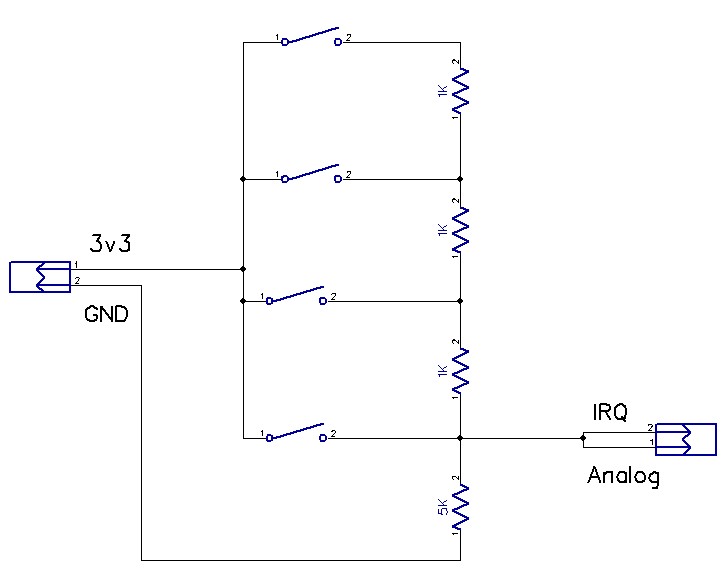
It's a voltage divider. Structured like this, it could trigger the IRQ pin when a button is pushed, and the analog pin could read the voltage to determine which button it was.@neverdie said in 6/8 Buttons battery remote node:
Here it is notionally for 4 buttons:
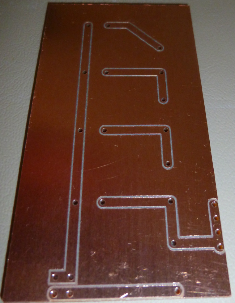
It's a voltage divider. Structured like this, it could trigger the IRQ pin when a button is pushed, and the analog pin could read the voltage to determine which button it was.I made a custom PCB to test the concept:
-
Tomorrow I'll try to bring out the arduino numeric keypad and an old sketch I used with it and see what I can do
@gohan said in 6/8 Buttons battery remote node:
Tomorrow I'll try to bring out the arduino numeric keypad and an old sketch I used with it and see what I can do
Cool! I didn't know there was an official Arduino keypad.
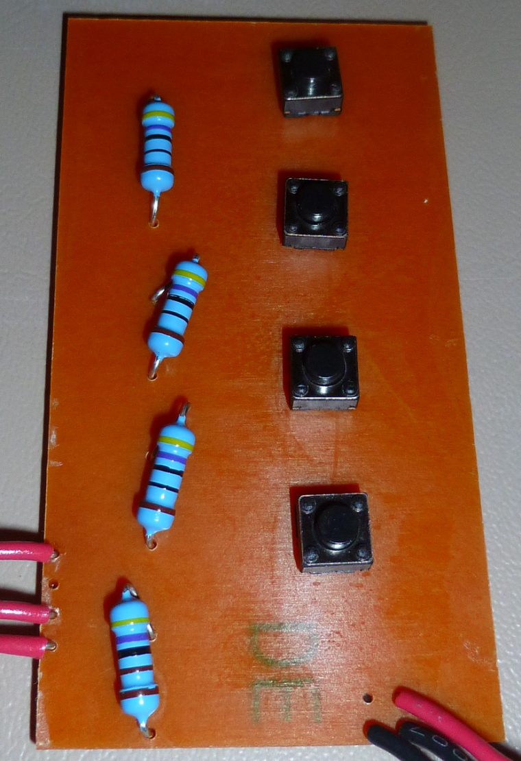
Here's mine:
-
It works. Connecting the output wires to A0 and D3, and running this script:
#include <avr/sleep.h>

void wake ()
{
  // cancel sleep as a precaution
  sleep_disable();
  // precautionary while we do other stuff
  detachInterrupt (1);
}  // end of wake

void setup() {
  pinMode(A0,INPUT);
  Serial.begin(115200);
  Serial.println("Starting...");
  Serial.flush();

}

void loop() {
  uint16_t voltage;

  set_sleep_mode (SLEEP_MODE_PWR_DOWN);
  sleep_enable();

  // Do not interrupt before we go to sleep, or the
  // ISR will detach interrupts and we won't wake.
  noInterrupts ();

  // will be called when pin D2 goes low
  attachInterrupt (1, wake, RISING);  //pin D3

  EIFR = bit (INTF1);  // clear flag for interrupt 1

  // turn off brown-out enable in software
  // BODS must be set to one and BODSE must be set to zero within four clock cycles
  MCUCR = bit (BODS) | bit (BODSE);
  // The BODS bit is automatically cleared after three clock cycles
  MCUCR = bit (BODS);

  // We are guaranteed that the sleep_cpu call will be done
  // as the processor executes the next instruction after
  // interrupts are turned on.
  interrupts ();  // one cycle
  sleep_cpu ();   // one cycle

  delay(100);  //debounce the button
  voltage=analogRead(A0);
  if (voltage>0) {
    Serial.println(voltage);
    Serial.flush();
  }
}
on a 3.3v Arduino pro mini yields these values for each of the four buttons:
Starting...
1023
930
852
787
The pro mini sleeps until one of the buttons gets pressed, then it wakes up, reads the value, displays the value, and then goes back to sleep. :)
-
It * might* get a little hairy though if running at 1.8v and you've got a lot of buttons to disambiguate and you still want to wake up on any button press. According to Table 32-2 of the atmega328p datasheet, the minimum threshold for input HIGH if running at vcc=1.8v-2.4v is 0.7Vcc. So, at the limit, that is 0.7*1.8v=1.26v. So, if n is the number of buttons, you need to disambiguate, then in a perfect world 0.54/(n-1) volts separates each button press. So, if say 12 buttons, that is 0.54/11=0.049 volts. Well, let's see: resolution is 1.8v/1023=0.0018v.
Hmm... Again, in a perfect world, that's 27 analog read units separating each button press. In an imperfect world, that's not a lot of headroom for disambiguation. I guess in the worst case you might have to run a one-time calibration for each button and store it in EEPROM. I would hope to avoid such a calibration step, but it might come to that.
@neverdie Is this not an instance where a high efficiency low dropout booster supply would null this particular issue?
-
@neverdie Is this not an instance where a high efficiency low dropout booster supply would null this particular issue?
@zboblamont said in 6/8 Buttons battery remote node:
@neverdie Is this not an instance where a high efficiency low dropout booster supply would null this particular issue?
Yes, that trade-off would relax the constraints.
But so does a one-time calibration. Since writing the above, I've warmed up to the idea. At least for my purposes, it's not that big a deal.
-
@zboblamont said in 6/8 Buttons battery remote node:
@neverdie Is this not an instance where a high efficiency low dropout booster supply would null this particular issue?
Yes, that trade-off would relax the constraints.
But so does a one-time calibration. Since writing the above, I've warmed up to the idea. At least for my purposes, it's not that big a deal.
@neverdie said in 6/8 Buttons battery remote node:
But so does a one-time calibration. Since writing the above, I've warmed up to the idea. At least for my purposes, it's not that big a deal.
What about resistance variation due to temperature changes ? :)
-
@neverdie said in 6/8 Buttons battery remote node:
But so does a one-time calibration. Since writing the above, I've warmed up to the idea. At least for my purposes, it's not that big a deal.
What about resistance variation due to temperature changes ? :)
@nca78 said in 6/8 Buttons battery remote node:
@neverdie said in 6/8 Buttons battery remote node:
But so does a one-time calibration. Since writing the above, I've warmed up to the idea. At least for my purposes, it's not that big a deal.
What about resistance variation due to temperature changes ? :)
I hadn't really thought about that. Should I? In my case (12 buttons on a remote control) I'm assuming the resistors stay more or less room temperature.
Hello! It looks like you're interested in this conversation, but you don't have an account yet.
Getting fed up of having to scroll through the same posts each visit? When you register for an account, you'll always come back to exactly where you were before, and choose to be notified of new replies (either via email, or push notification). You'll also be able to save bookmarks and upvote posts to show your appreciation to other community members.
With your input, this post could be even better 💗
Register Login