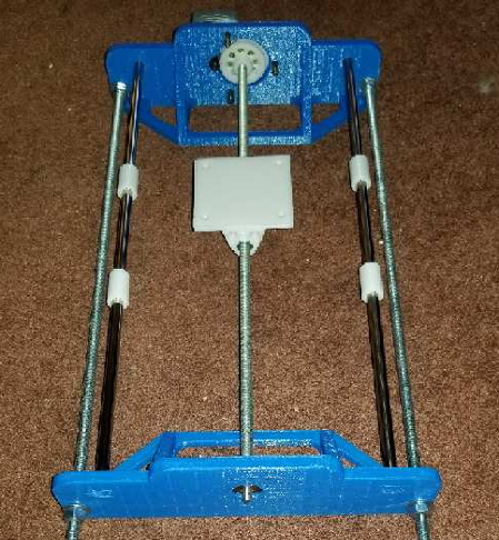
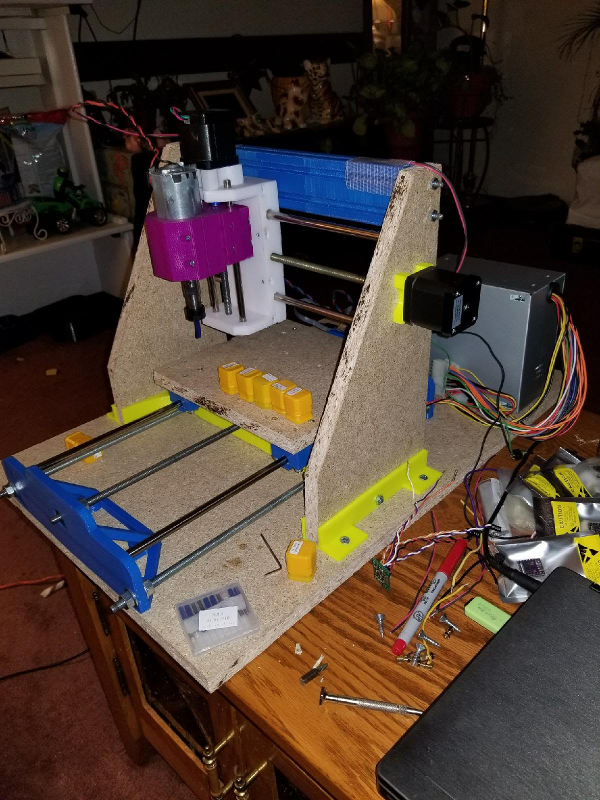
DIY CNC mill from mainly salvaged and 3D printed parts

-
I haven't had a chance to test the accuracy of the machine yet, but I did find a web page that has a VERY useful calculator for figuring out your steps per mm for a lead screw type system.
https://www.prusaprinters.org/calculator
Scroll down to the section labeled "Steps per millimeter - leadscrew driven systems". You just enter the parameters of your motor, microstepping, gear ratio (if any) and lead screw type/size. From that it calculates the steps per mm that is needed to configure your X, Y and Z axes for your GRBL controller.Figured this may be useful to others.
-
Or use a dial gauge and get an exact measurement.
-
That should work. Here's what I meant though:
-
That should work. Here's what I meant though:
-
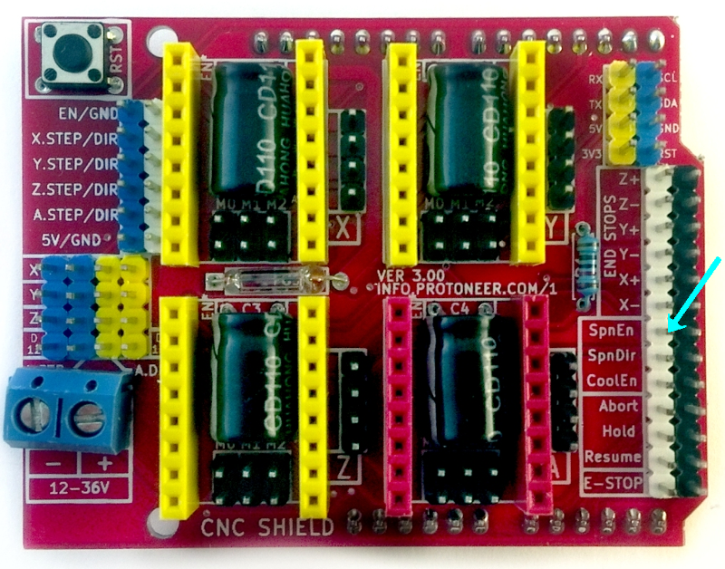
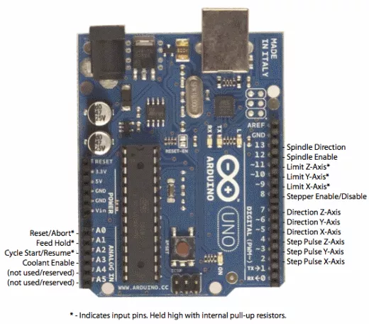
So I am trying to get my spindle control set up and I am having an issue. I am checking with a volt meter between the spindle enable (SpnEn) and ground and I am reading 5v. No matter what spindle commands I am sending (M03, M04 or M05) I am always reading 5v. Is there a different command for spindle enable? If I check the spindle direction pin (SpnDir), I read 5v when I send M03, and 0v when I send M04. So that appears to be working.
-
So I am trying to get my spindle control set up and I am having an issue. I am checking with a volt meter between the spindle enable (SpnEn) and ground and I am reading 5v. No matter what spindle commands I am sending (M03, M04 or M05) I am always reading 5v. Is there a different command for spindle enable? If I check the spindle direction pin (SpnDir), I read 5v when I send M03, and 0v when I send M04. So that appears to be working.
@dbemowsk
On my board,
M3 SP1000
spins the spindle at maximum speed. Just M3 by itself doesn't.
It's not obvious from looking at your board where the spindle OUT voltage is. Maybe on the opposite side? I guess you'll have to probe around to find it. -
@dbemowsk
On my board,
M3 SP1000
spins the spindle at maximum speed. Just M3 by itself doesn't.
It's not obvious from looking at your board where the spindle OUT voltage is. Maybe on the opposite side? I guess you'll have to probe around to find it.@neverdie The SpnEn and SpnDir are control signals. For this board you need to have an external motor driver. After some looking, I may have found my answer. I am running GRBL 1.1. It appears that they swapped 2 of the pins. Pin 12 used to be the spindle enable pin in GRBL 0.9. In 1.1, they swapped 11 and 12 because pin 12 cannot be used for PWM which is how the controller limits the speed. I have not tried it yet, but I am going to try the Z+ pin which is pin 11. If that works, I may do a slight board mod.
Here is the post that explains it. https://github.com/grbl/grbl/issues/1187
-
Yes, my typo, just S, not SP.
I do wonder whether some of the more "advanced" boards, like the Duet WiFi, actually perform better, or whether the results are the same.
I think I may get a RAMPS board, if only because it supports Marlin, and that's what the MPCNC uses.
On the other hand, there is a smoothieboard clone on aliexpress for $40. . Hmm... It's tempting....
The jump from GRBL 0.9 to 1.1 convinced me that the firmware can make a difference, that it's not just all equivalent.
@neverdie I have always said, at least for 3D printers, that RAMPS was the way to go if you had to change your main board. Many of these 3D printer main boards have everything integrated into them. With RAMPS, it is all modular. If something dies, you are replacing 1 part rather than an entire board.
-
@neverdie I have always said, at least for 3D printers, that RAMPS was the way to go if you had to change your main board. Many of these 3D printer main boards have everything integrated into them. With RAMPS, it is all modular. If something dies, you are replacing 1 part rather than an entire board.
@dbemowsk I'll give it a shot. I ordered a mildly upgraded RAMPs board (so called "version 1.6"). It doesn't have the re-settable fuses, which I guess have a dodgy reputation (or so Tom Sanlanderer seems to imply).
https://www.aliexpress.com/item/Bigtreetech-upgrade-Ramps-1-5-Base-on-Ramps-1-4-3D-control-panel-printer-Control-Reprap/32822038995.html?spm=a2g0s.9042311.0.0.9zbnJj
I'll be curious as to whether it can accept either the TMC2130 or the TMC2660 modules. -
@dbemowsk I'll give it a shot. I ordered a mildly upgraded RAMPs board (so called "version 1.6"). It doesn't have the re-settable fuses, which I guess have a dodgy reputation (or so Tom Sanlanderer seems to imply).
https://www.aliexpress.com/item/Bigtreetech-upgrade-Ramps-1-5-Base-on-Ramps-1-4-3D-control-panel-printer-Control-Reprap/32822038995.html?spm=a2g0s.9042311.0.0.9zbnJj
I'll be curious as to whether it can accept either the TMC2130 or the TMC2660 modules.@neverdie I think most of those stepper driver modules run the same footprint. Check out this link. It is from Tom's 3D forum. People there are talking about those as replacements for the DRV88256's, which are the ones that I have. May be some useful info for you.
https://discuss.toms3d.org/hardware-f6/drv8825-vs-tmc2100-vs-tmc2130-vs-tmc2208-t250.html -
@neverdie I think most of those stepper driver modules run the same footprint. Check out this link. It is from Tom's 3D forum. People there are talking about those as replacements for the DRV88256's, which are the ones that I have. May be some useful info for you.
https://discuss.toms3d.org/hardware-f6/drv8825-vs-tmc2100-vs-tmc2130-vs-tmc2208-t250.html@dbemowsk Short of making a very careful study of the datasheets, the other info that's available is awfully sketchy, so I ordered one of each module, and I'll see if I can get either one to work on the RAMPS board that I ordered. I'm not completely sure, but I get the impression that after they are properly configured, they can maybe just plug and play.
-
So, here is the latest update with pictures. I have the whole setup mounted on a leftover piece of MDF. I am using an ATX computer power supply to run everything. The fan pulls air from the back of the setup and blows it over the heatsinks for all of the modules.
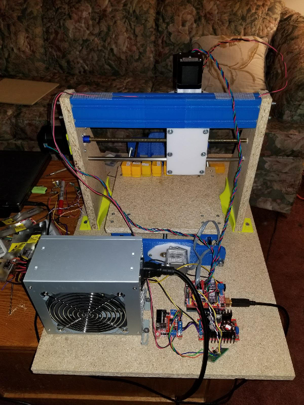
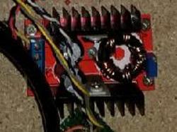
For spindle control I have 3 different modules. The first is a buck converter to boost the 12 volts to 24 for running the spindle motor.
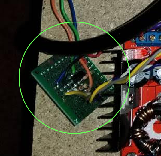
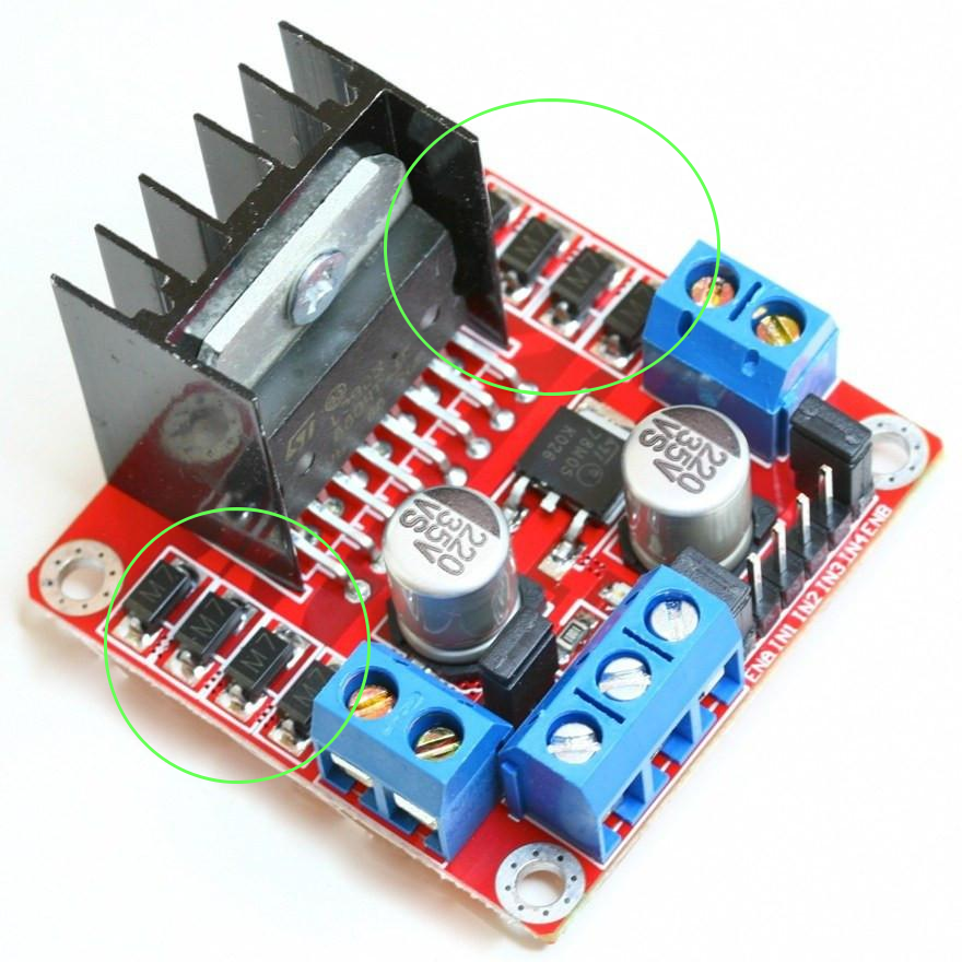
Next I have a dual H-Bridge that I had in my parts bin. I am only using one side of it. This handles the motor direction and speed. One problem with it that I had to overcome was that it had separate logic inputs for forward and reverse. The problem was that the CNC shield had a single output for spindle direction. To overcome this, I made a simple not gate circuit using an NPN switching transistor which sends a normal logic level to one input pin and an inverted signal to the other. I then use the enable line to start and stop the spindle. This setup works well.
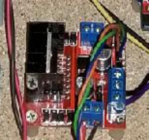
This is the entire spindle drive circuity.
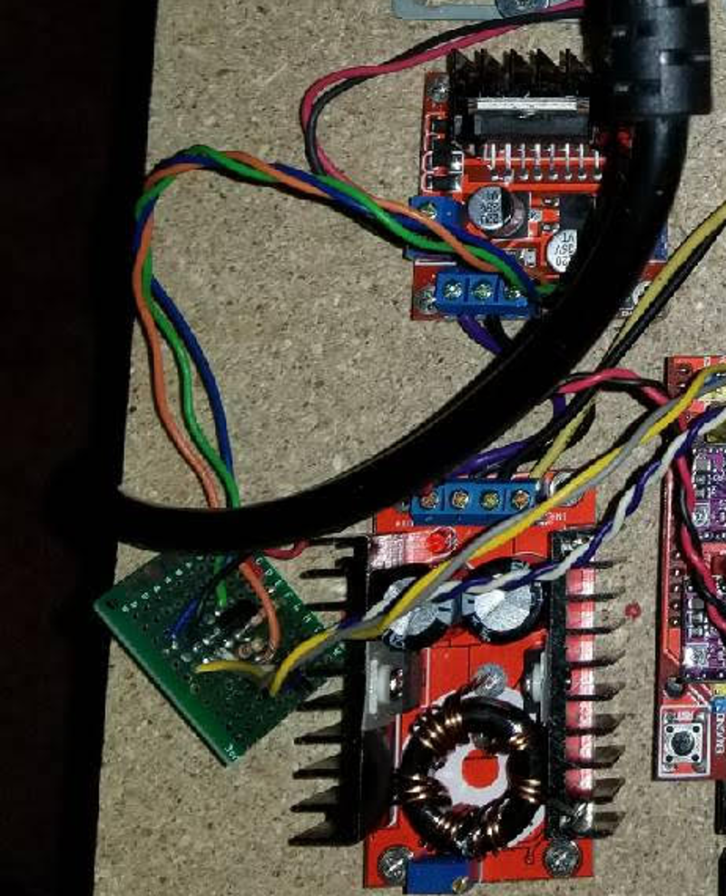
Here is an angled front view.
-
Don't forget to include a snub diode on the motor, if you haven't already.
-
I like the idea of recycling an old PC power supply with a boost converter. For instance, a lot of the 48v power supplies don't come with regular 110VAC plugs, and you're even left with semi-exposed 110VAC wiring, so this kinda works around that. It's a bit ungainly, but it works.
The only problem is you probably can't get to more than 240w, as that would be 20amps at 12v to the input of the boost converter. Actually less than 240w because of conversion inefficiency. At best probably just 0.85*240=204w. Maybe it would be good enough for milling PCBs though.
Hello! It looks like you're interested in this conversation, but you don't have an account yet.
Getting fed up of having to scroll through the same posts each visit? When you register for an account, you'll always come back to exactly where you were before, and choose to be notified of new replies (either via email, or push notification). You'll also be able to save bookmarks and upvote posts to show your appreciation to other community members.
With your input, this post could be even better 💗
Register Login