nRF5 action!
-
For instance, this buttonless approach stays in DFU mode for 30 seconds after a reset: https://thingtype.com/blog/dfu-ota-updating-an-nrf52-application-over-the-air/
I guess maybe that's the shortest path out of this dilemma.
-
For instance, this buttonless approach stays in DFU mode for 30 seconds after a reset: https://thingtype.com/blog/dfu-ota-updating-an-nrf52-application-over-the-air/
I guess maybe that's the shortest path out of this dilemma.
-
@neverdie but all those bootloaders rely on bluetooth (thus softdevice) for DFU, that means we need to write our custom bootloader which uses different transport.
@monte said in nRF5 action!:
@neverdie but all those bootloaders rely on bluetooth (thus softdevice) for DFU, that means we need to write our custom bootloader which uses different transport.
In a perfect world, yes. However, since that doesn't yet exist, the question is: what else, if anything, can be done today?
-
@monte said in nRF5 action!:
@neverdie but all those bootloaders rely on bluetooth (thus softdevice) for DFU, that means we need to write our custom bootloader which uses different transport.
In a perfect world, yes. However, since that doesn't yet exist, the question is: what else, if anything, can be done today?
@neverdie said in nRF5 action!:
In a perfect world, yes. However, since that doesn't yet exist, the question is: what else, if anything, can be done today?
Today is either use bluetooth/ant/thread (all need softdevice) or write your own OTA bootloader for legacy radio without softdevice.
-
Looks as though micropython does support the bluetooth stack for both nRF52832 and nRF52840: https://github.com/micropython/micropython/tree/master/ports/nrf
Micropython also runs on the nRF51, but apparently (judging from the BBC micro:bit), there's not also enough extra space to also support the bluetooth at the same time on the nr51.
@neverdie Speaking of micropython: Adafruits fork of micropython (called circuitpython) now also supports the nRF52840. The also added the nRF52840 dongle as make target (pca10059). After compiling, you can use nRF Connect to flash the hex file to the dongle, via the stock USB DFU bootloader, so you don't need an extra programmer.
I like that dongle, it's cheap yet powerful, and it may be the smallest micropython-capable board with native USB. Native USB is nice, because in this case it has not only a serial REPL, but also a virtual drive with the code files, like the original pyboard.
-
After running through a gauntlet, I managed to get micropython running on the nRF52832-DK! I posted the firmware here: https://forum.micropython.org/viewtopic.php?f=2&t=5343&p=30756#p30756 to spare anyone else from running the same gauntlet. Just copy the firmware.hex file directly to the nRF52832-DK drive on your PC, and it will upload automatically to the DK and start running micropython. )
-
@toyman Micropython on the BBC micro:bit (which uses the nRF51822) has a Radio library that uses Nordic's proprietary radio modes and doesn't involve Bluetooth. I suppose the question is: what would be involved in getting it to run on the nRF52832 or the nRF52840. Seems like it would be substantially the same.
Faiing that, if I can directly manipulate the radio registers from miropython as I can from C, then it shouldn't be too hard to get at least minimal radio capability up and running from within micropython.
If I can get rudimentary radio communications working in micropython, then from there it should be easy to do OTA updates via REPL. I did some proof of concept to that effect on the micro:bit, but quickly ran out of memory--the micro:bit has only a total of 16K of RAM, so there's very little headroom to begin with. On the nRF52840, lack of RAM shouldn't be an issue.
-
@scalz hinted at it previously, but it looks like MyNewt OS might offer yet another way to do OTA updates. According to their posted information, it offers:
A open-source Bluetooth 5.0 stack (both Host & Controller), NimBLE, that completely replaces the proprietary SoftDevice on Nordic chipsets. (https://github.com/apache/mynewt-core/blob/master/README.md)
Apparentlly it runs on both the nRF52832 and the nRF52840.
@neverdie
1737 posts and counting
Spend hours reading this. Amazing journey so far. -
@toyman Micropython on the BBC micro:bit (which uses the nRF51822) has a Radio library that uses Nordic's proprietary radio modes and doesn't involve Bluetooth. I suppose the question is: what would be involved in getting it to run on the nRF52832 or the nRF52840. Seems like it would be substantially the same.
Faiing that, if I can directly manipulate the radio registers from miropython as I can from C, then it shouldn't be too hard to get at least minimal radio capability up and running from within micropython.
If I can get rudimentary radio communications working in micropython, then from there it should be easy to do OTA updates via REPL. I did some proof of concept to that effect on the micro:bit, but quickly ran out of memory--the micro:bit has only a total of 16K of RAM, so there's very little headroom to begin with. On the nRF52840, lack of RAM shouldn't be an issue.
@neverdie There are three ways to manipulate registers directly from Micropython:
-
Use machine.mem16
-
Use the decorator @micropython_viper
The Viper code emitter implements integer types and pointers, allowing to access memory and registers directly. -
Use the decorator @micropython.asm_thumb
Write your code in ARM assembler.
Problem: I don't know whether any of this is already implemented and works reliably in Micropython for nRF.
-
-
@neverdie
1737 posts and counting
Spend hours reading this. Amazing journey so far.@speechsupply this thread is golden. I was so empowered that was able to easily switch to nRF SDK and to start producing (semi) commercial BLE-ANT device
-
@speechsupply this thread is golden. I was so empowered that was able to easily switch to nRF SDK and to start producing (semi) commercial BLE-ANT device
@toyman
Yea, On monday I'll order a couple of nRF52840 EVAL boards. Any suggestion regarding what to get?
Looked at both the BMD-340-EVAL and ofcourse the NRF52840-DK -
@neverdie There are three ways to manipulate registers directly from Micropython:
-
Use machine.mem16
-
Use the decorator @micropython_viper
The Viper code emitter implements integer types and pointers, allowing to access memory and registers directly. -
Use the decorator @micropython.asm_thumb
Write your code in ARM assembler.
Problem: I don't know whether any of this is already implemented and works reliably in Micropython for nRF.
@uhrheber said in nRF5 action!:
@neverdie There are three ways to manipulate registers directly from Micropython:
-
Use machine.mem16
-
Use the decorator @micropython_viper
The Viper code emitter implements integer types and pointers, allowing to access memory and registers directly. -
Use the decorator @micropython.asm_thumb
Write your code in ARM assembler.
Problem: I don't know whether any of this is already implemented and works reliably in Micropython for nRF.
Thanks! We finally nailed it all the way down on this thread here: https://forum.micropython.org/viewtopic.php?f=12&t=5377
:smiley:
-
-
I see somewhat strange behaviour when using millis() for intervals.
I'm not sure it's my mistake, but one thing is that it seems that the millis rollover is around; 131.068.570 (36 hours)
When the rollover happens, it looks like it interrupts my sleep. Does that make sense?
sleep(digitalPinToInterrupt(PIR_Pin), CHANGE, LongSleep);Debug lines => (Temp / RH - Millis)
21.44 / 61.15 - 130977952
21.43 / 61.16 - 131008158
21.42 / 61.15 - 131038364
21.44 / 61.14 - 131068570
I woke up because I saw movement at: 26576
Sleep Duration : -131042000  Im going back to sleep for 150000
21.43 / 61.16 - 176822
20-10-2018 => its been ±36 hours laters, and he woke up again at the same moment.
18.57 / 56.88 - 131007553 18.56 / 56.86 - 131037759 18.58 / 56.85 - 131067965 I woke up because I saw movement at: 25971 Sleep duration : -131042000 => Rollover?? 18.55 / 56.89 - 206423 18.53 / 56.89 - 236628 18.54 / 56.90 - 266834 18.55 / 56.89 - 297040 18.54 / 56.90 - 327246 -
I have the same problem with brand news ebyte modeules.
Here are my openocd logs:
Open On-Chip Debugger 0.10.0-dev-gdc53227 (2016-04-09-13:45)
Licensed under GNU GPL v2
For bug reports, read
http://openocd.org/doc/doxygen/bugs.html
debug_level: 2
0x4000
Info : The selected transport took over low-level target control. The results might differ compared to plain JTAG/SWD
adapter speed: 10000 kHz
Info : Unable to match requested speed 10000 kHz, using 4000 kHz
Info : Unable to match requested speed 10000 kHz, using 4000 kHz
Info : clock speed 4000 kHz
Info : STLINK v2 JTAG v17 API v2 SWIM v4 VID 0x0483 PID 0x3748
Info : using stlink api v2
Info : Target voltage: 3.241270
Info : nrf52.cpu: hardware has 0 breakpoints, 2 watchpoints
Error: timed out while waiting for target halted
TARGET: nrf52.cpu - Not halted
in procedure 'program'
in procedure 'reset' called at file "embedded:startup.tcl", line 478
in procedure 'ocd_bouncer'embedded:startup.tcl:454: Error: ** Unable to reset target **
in procedure 'program'
in procedure 'program_error' called at file "embedded:startup.tcl", line 479
at file "embedded:startup.tcl", line 454
wybrany port szeregowy at file "embedded:startup.tcl", line 454
nie istnieje albo Twoja płytka nie jest podłączona@maciekczwa said in nRF5 action!:
Licensed under GNU GPL v2
For bug reports, read
http://openocd.org/doc/doxygen/bugs.html
debug_level: 2
0x4000
Info : The selected transport took over low-level target control. The results might differ compared to plain JTAG/SWD
adapter speed: 10000 kHz
Info : Unable to match requested speed 10000 kHz, using 4000 kHz
Info : Unable to match requested speed 10000 kHz, using 4000 kHz
Info : clock speed 4000 kHz
Info : STLINK v2 JTAG v17 API v2 SWIM v4 VID 0x0483 PID 0x3748
Info : using stlink api v2
Info : Target voltage: 3.241270
Info : nrf52.cpu: hardware has 0 breakpoints, 2 watchpoints
Error: timed out while waiting for target halted
TARGET: nrf52.cpu - Not halted
in procedure 'program'
in procedure 'reset' called at file "embedded:startup.tcl", line 478
in procedure 'ocd_bouncer'**embedded:startup.tcl:454: Error: ** Unable to reset target ****
in procedure 'program'
in procedure 'program_error' called at file "embedded:startup.tcl", line 479
at file "embedded:startup.tcl", line 454
wybrany port szeregowy at file "embedded:startup.tcl", line 454maybe someone else already found the solution, but it took me a while to figure it out for myself.
So for documentation sake:
Just had the exact same things with new Ebyte NRF52832 modules, ST-Link v2 couldn't erase it. (the old once did erase without a single problem )
After some digging, I found the following:
(I'm using my NRF52832-DK for it, maybe other devices work as well, just tested this one)DK => Ebyte module
GND(detect) => GND
SWDIO => SWDIO
SWDCLK => SWCLK
VTG => 3,3V
3,3V => 3,3V
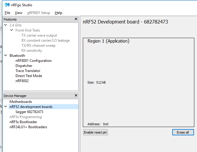
GND =>GNDyou can erase the protection using nRFgo Studio
- On the left, you can find a header named Segger, click on that.
- then it shows that it is locked, and you can click recover.
- after that you can erase it
- upload a new sketch using an ST-link V2 or the DK while you are still at it.
Hello! It looks like you're interested in this conversation, but you don't have an account yet.
Getting fed up of having to scroll through the same posts each visit? When you register for an account, you'll always come back to exactly where you were before, and choose to be notified of new replies (either via email, or push notification). You'll also be able to save bookmarks and upvote posts to show your appreciation to other community members.
With your input, this post could be even better 💗
Register Login