What did you build today (Pictures) ?


  • My wife said "I do not want to see "those things""...
    Challenge accepted!

    0_1544224086865_TV LED display 1 - 20181207_171500.jpg

    1_1544224086867_TV LED display 2 - 20181207_183612.jpg

    0_1544224266422_MVI_5770.00_00_03_13.Still001.jpg

    (see the gif in action here https://ibb.co/BCbS2Dc )


  • Milled some PCA9615 differential I2C converters for the sensors ouside: magnetometer for the gas meter, temp/hum, baro.
    Until now I've used a 7 meter long cable, but whenever the gas water heater fired up the Arduino would just freeze losing the count of gas pulses, I've tried shielded cable but it hasn't solved the issue.
    Since Sparkfun's breakout boards are on the wrong side of the pond I decided to make my own.
    Really hope the Arduino doesn't lock up anymore.

    LE. That TSSOP10 was a b*tch to solder šŸ˜

    0_1544228821399_IMG_20181207_192354.jpg 0_1544228904350_IMG_20181207_200947.jpg 0_1544228912010_IMG_20181208_000800.jpg


  • Hardware Contributor

    @dakipro woaw!!! šŸ‘


  • Hardware Contributor

    @dakipro thank you that's what I planned to do but wasn't sure it would be visible through the plastic layer.
    Coupled with capacitive sensors it could give awesome results !


  • @dakipro
    great job šŸ™‚
    , and also the show on TV is quite funny, those two Englishmen in US buying old cars renovating and selling those


  • @nca78 I used white decorative self adhesive wallpaper, so not sure which plastic you are planing to use, but you can easily test that before mounting I think. If you go for paper/foil, put some one-peace plastic in front of the displays as they (mine) are not perfectly soldered in line, so they are noticeable sa foil will glue to them. Not a big deal for me, but would love "the perfection". But yeah, plastic or some harder material would work awesome I think.

    All in all, not difficult project and a very high wow-factor/time-spent value (and waf)


  • Hardware Contributor

    @dakipro ah ok you cheated šŸ˜„

    I thought you kept the plastic layer that's glued on top of the wood panel. I'll try to get some samples from the company selling those here and make some tests then.


  • @dakipro
    BTW I can only recommend to spray your bare cobber wires with Plastic 70, as this will protect your cobber from corrosion with a thin layer acrylic

    0_1544345727981_plastik_70.png


  • Try this one.
    The smallest board I have ever assembled using just a hot fan. A solar battery charger based on BQ25504 from a solar panel. Almost all components are 0402. Far too small for my liking, but can go under the solar panel.

    0_1546964306401_FFE84E8C-991D-4342-8272-2180F79333A8.jpeg


  • Looks great. I'm still happy when I get an 0805 down well. Guess I have to keep practicing.


  • Hardware Contributor

    @nagelc said in What did you build today (Pictures) ?:

    Looks great. I'm still happy when I get an 0805 down well. Guess I have to keep practicing.

    Try solder paste applied with a thin needle, and a hot air gun at minimum speed (so components don't fly away). Then it's really easy to do SMD šŸ™‚


  • @nca78 there many other aspects. Iā€™m using a low temp melting solder paste. I have been using only a top quality (no AliExpress) one from Chipquick. It has to be stored property in the fridge.

    Using stencil may help. Iā€™m not using it and have to doze the paste very precisely which is a challenge. This is why my soldering is not 100% consistent, but it works. With 0402 components it is not easy - the pad size is very small.

    However, I must admit, 0402 are far too small. In the process, unless your space / lab is very well organised many components are lost. And a good magnifying glass / microscope is a must too. In the future, iā€™ll try to stick to 0805 or larger - these are a bit larger and more visible.

    All in all, this is not as difficult as many people may think. With a little bit of practice, this can be done.


  • @nagelc try 0603 size first. I am sure you will manage it with 0402 with a good microscope ;-))

    Iā€™m still using a magnifying glass which is an extra challenge. Eventually I will have to buy a good microscope


  • Mod

    @alexsh1 how much did one module cost?


  • Hardware Contributor

    Today i recieved my new mini-easy-pcb i posted some info about 3 months ago. This with a breakoutboard-daugher board for all "common" sensors in the MySensors shop. I want to create a small motherboard which can be powered using a battery but also can use the battery for UPS/backup if powered from another daugherboard. The motherboard should be standard and then I would be able to add 1-2 daugherboards to specify the node.

    The breakoutboard is just for test, but can be used by newbies offcourse.
    My wish is to create the ultimate security sensor running on 12v but with a battery backup. It should include motion, temp, smoke and light.

    0_1548081587912_377d9c22-187f-4482-812f-80bb7d553bce-image.png

    0_1548081617961_8349e553-898f-4e17-b29d-87eba091e53c-image.png

    Il will get back in another 3 months when tested šŸ˜‰


  • @sundberg84 Nice job.


  • @nca78
    Thanks for giving me a push. I had used hot air only for removing parts. I got some paste and populated my first board. So easy compared to the soldering iron.


  • @gohan module? you mean the PCB? or total?


  • So for some time now I have been working on a conversion to my 3D printer to allow me to change between different tool heads easily, thus increasing the versatility of the machine. To jump right in and give a little background on the mod, I have a plate that mounts to my X carriage that has 4 10mm neodymium magnets in it. These magnets hold the tool in place that will be used which also has 4 magnets in it's mounting plate.0_1549168718079_Resized_20181230_084440_8356-2.jpg
    0_1549168740823_Resized_20181230_084411_8868-2.jpg
    The first tool that I did was my 3D printer head. I obviously did that one first because I would need that to make future parts and tool heads to expand the machine. Here is my 3D printer head mounted to the working assembly.
    0_1549169544562_Resized_20190118_013816_2670.jpg
    Another tool head that I made for this is my simple pen plotter tool for drawing.
    0_1549169817834_Resized_20190202_225547_6180.jpg
    Here is a sample of something I did with the pen plotter using fine point sharpie markers. The left is the original image, and the right was done with the plotter.
    0_1549170644769_0f86124a-cf32-4e8a-a078-f2e4870df5a3-image.png
    The most recent tool head that I did was my laser engraver tool. This tool is the main reason for this post. This is the 6 watt laser module mounted to the carriage.
    0_1549170198674_Resized_20190202_230033_4069.jpg
    So what I am looking to do with this on the MySensors end of things is to build some sort of flame sensor that can monitor the engraving operation to indicate a small fire and take some sort of action, and also report it to my vera controller. Exactly what action I would have it take I have not figured out yet. If anyone has suggestions I'm all ears. I was thinking of something that could easily extinguish the small flame. As for the flame sensor, I know they make these small flame sensor modules, but I don't know how reliable they are, ore even how they work.
    0_1549171496732_6c6a2026-c4f2-408a-83a5-745076ec537d-image.png

    For anyone interested, here is a sample engraving on a piece of thin plywood. The left image is the original. The center is at a low resolution, and the right one was at a high resolution.
    0_1549172116707_f5a6f311-a35e-4363-8e9d-e4c3cb6460a6-image.png
    One other thing that I want to test with this is I've seen people that make circuit boards with these. They spray a layer or two of paint on their blank copper clad and then laser etch their pattern on the painted surface. Then they run it through their ferric chloride or other etching solution. Finally, sand off the layer of paint.

    Any suggestions or help people can give is greatly appreciated. Thanks for viewing.


  • Mod


  • @mfalkvidd Not a bad idea. I could get a CO2 canister with a solenoid valve and hook it to a hose that would blow CO2 directly onto the flame to put it out. Since my 3D printer is in an enclosure, it should contain the CO2 helping further extinguish the flame.


  • Admin

    @dbemowsk

    Cool setup, is the adapter system stable enough for the different tools? Mainly the extruder for the 3d printing?


  • @tbowmo With the 4 recessed indents on the plate, it centers the tool being mounted pretty good. I have printed a number of things with it since the upgrade and haven't had any issues with it yet. The Makerbot Replicator series of printers use a similar way of attaching their Smart Extruder heads with the 4 magnets in the corners.
    0_1549405568093_d4143092-fc52-4f28-a738-8938b2181ad4-image.png

    One difference between the Makerbot extruders and my setup is that the Makerbots put their extruder stepper behind the hot end assembly and that mates to the motor with a castle nut type assembly.
    0_1549406115458_a97a2379-85fb-4247-8c5f-dfdec50722cf-image.png

    My setup uses a Bowden extruder setup that is mounted at the top of my enclosure.
    0_1549406227269_a9f59e50-adae-484d-85e9-9d79c9eaf733-image.png
    With no stepper on my hot end, that takes the majority of the weight off of the carriage. This is one of the first tests of the 3D printer head.
    3D printing tool test ā€“ 02:09
    ā€” Dan Bemowski


  • Admin

    @dbemowsk

    One extra question, what type of filament did you use to print the adapter plates in?


  • @tbowmo All the parts are in PETG. I got the 1kg roll cheap on Amazon for $12 US with prime shipping.


  • For anyone interested in my 3D printer mod for using different tools, I posted it on thingiverse.
    https://www.thingiverse.com/thing:3407486


  • Built a 1284(p) into a 328p Pro Mini footprint. Not sure what to call it, a Pro Mini XL maybe?

    0_1549628124362_328p Pro Mini vs. 1284p Pro Mini XL.jpg

    I now have x4 the program memory (128K vs. 32K), x4 the EEPROM (4K vs. 1K) and x8 the SRAM (16K vs. 2K) all in a 328p Pro Mini pin-compatible (I think!) footprint of about same size.

    I can also run at 20MHz vs. the usual 8MHz provided Iā€™m prepared to run it at 4.5v and above.

    Had to sacrifice a few pins and components, but might be able to put various selections back in future revisions. Nothing major (in my opinion) just components associated with the regulator really. I also went for a crystal (not installed yet, on order, LEDs too..) over a resonator - just a personal preference for when timing is critical.

    And yes, those are 0402 SMDs. I actually did them by hand (!) with a microscope and a judicious amount of coffee; a fine-point iron, solder wick and flux became my best friends.

    So far, Iā€™ve had it working with nRF24s and RFM69s radios, ATSHA for personalization and external flash for FOTA. The DualOptiboot bootloader code and makefile needed a bit of tweaking, but nothing major.

    I broke out the JTAG I/F but havenā€™t played with that yet and also added power pins next to the I2C to make some of the sensor modules (like SI7021) pluggable - see below.

    0_1549628236323_Pro Mini XL with RFM69HW ATSHA EEPROM and SI7021.jpg

    I also want to play with the QTouch library support for built-in capacitive touch buttons, sliders, etc.

    Why not just go with an ARM (STM32, SAMD, nRF52)?

    Iā€™m working on it! ;o)

    Am not wanting to start a(nother) 8-bit vs. 32-bit discussion. Iā€™ve got an AliExpress package of 32-bit MCUs coming (very) slowly to me. When it arrives, Iā€™ll start experimenting and exploring - probably with the nRF52s, since those seem to be the flavor-of-the-month and very capable-looking chips...

    But until then, I need more program memory!
    (Among other thingsā€¦)


  • Finally finished building my dual precision voltage reference LTC6655:

    0_1549896394457_B2F58A87-E2DB-436B-ADFA-0514F43D2AAA.jpeg


  • @acb I have built similar board.
    0_1549896894038_41B5EC1D-BA6B-4ADA-BE5D-9CB48359207D.jpeg

    The only downside is the cost and size of Atmega1284p is just so prohibitive. Yet it is 8 bits processor. I have only one fully conpleted board and a few blank pcbs.


  • That looks awesome @alexsh1!

    Nicely laid out and cleanly soldered. Was that with an iron or hot air (or both)? Nice clear silk too; I like the power and ā€œsignalā€ symbols. Did you ever try a FOTA update with it? Or a low power/speed profile?

    I see you went a bit wider and longer than the standard Pro Mini, (Iā€™m assuming) to get at all the pins and add the extra regulator, LEDs, etc.

    I was constrained by needing something that fit the same footprint for existing boards I already had, e.g. other ā€œmotherboardsā€ Iā€™d made similar to @sundberg84ā€™s excellent Easy/Newbie PCB or wanting pin-compatibility for stacking boards like the ATSHA+EEPROM+Radio+ICSP one below:

    0_1549963211745_06 - Pro Minis with ATSHA, Ext. Flash, Radio & ICSP.jpg

    I tried routing with the chip at a 45 degree angle too but couldnā€™t get a DRC to pass with the pads so close to the PTHs. I may try again with shorter (custom) TQFP pads...

    Re: 1284pā€™s downsides of cost and size.

    I know. I ended up justifying it to myself this way:

    We can all get cheap 328p Pro Minis from Ali for around $2. The vast majority of my Pro Mini projects are battery powered, so thereā€™s some ā€œlabor costā€ to disable the power LED and remove the regulator. But regardless, I certainly canā€™t make myself a low(er) power Pro Mini for $2 - the OSH Park PCB alone is probably close to that.

    I think the cheapest I ever got 1284p chips for was around $2.50, again from Ali. My ā€œPro Mini XLā€ PCBs were around $1.70 from OSH Park, add a sprinkling of 0402s, etc. and weā€™re probably at around $5.

    I couldnā€™t find any 1284p-based boards near that price. The closest I got was Kevinā€™s Mini Duino, which is another lovely looking board, but doesnā€™t fit my need for a Pro Mini-constrained size and pin-compatibility. Essentially, I was after something close to a drop-in replacement.

    So, $2+ versus $5+ for all the benefits (at least as far as I was concerned) listed above? It became a bit of a no-brainer.

    And on the low power front, I profiled the MySensors library sleep command on it at around 5uA on 4.5v @ 20MHz using an external full swing, around 4uA on 3v @ 8MHz and around 3uA on 1.8v @ 1MHz Internal RC Osc:

    0_1549963330901_03 - 3.2uA in Power-save Mode - ATMEGA 1284 on 1.8v at 1MHz Int. RC Osc.JPG

    Those numbers are certainly good enough for all my current applications - no pun intended! šŸ˜‰

    But I would like to look at the 32-bit contenders as potential replacements.

    Iā€™ve seen nRF52s with 512K for around $2 on Ali, so maybe Iā€™ll try my hand at a Pro Mini nRF52 or something similar eventually. The board above was a fun challenge, and afterall is what this is (mainly) about for me.


  • @acb Nice pro mini sized 1284 boards. These would work nice in my in-wall OLED scene controller boards. The standard 328 pro minis really limit what I can do with the OLED display when using it with the MySensors library. I could get more use out of the graphics end of the display with something like that.

    Do you have these on OpenHardware.io? Can fully functional boards be purchased somewhere? I would be interested in trying a few out if possible.

    Kudos on the design.


  • Thanks for the kudos, @dbemowsk. Right back at you for your scene controllers; Iā€™m trying to get into 3D design myself, but canā€™t justify the time commitment right now.

    Re: Do you have these on OpenHardware.io?

    No, sorry, that would require me to be far more organized than I am at present! šŸ˜‰

    Maybe if there was enough interest, I could justify putting in the time to clean things up enough to publishā€¦ But it is valentines today, so any tinkering will surely be met with an icy stare if I try it tonight! šŸ˜®

    Re: Can fully functional boards be purchased somewhere? I would be interested in trying a few out if possible.

    Really? Iā€™ve never done something like that before. You do realize these are very much ā€œalphaā€ right? I mean, Iā€™ve tested the majority of the pins, but nothing like proper production hardware verification or anything. Having said that, itā€™s not like thereā€™s anything complicated going on.

    I managed to dig out four spares this afternoon that Iā€™m not using from the last batch I made - how many would you like?

    0_1550175379519_07 - 4x Pro Mini XLs.JPG

    Three have a 1284p attached and one has the regular 1284 - I believe the only difference is the 1284 doesnā€™t have BOD, but I normally turn that off anyway for a (probably) miniscule power saving. I havenā€™t installed the crystal oscillator or reset switch yet. I donā€™t normally do that until I know what the use-case is. I believe I have enough spare 16MHz and 20MHz ones to fit (maybe some 8s) and some SMD reset switches too.

    The only other thing would be the bootloader. I could flash the standard MySensors DualOptiboot?

    So, if you (or I suppose anyone else for that matter) are interested, just shoot me a chat message via my profile and we can figure things out off-thread, as this is a bit off-topic now.

    Thanks again for the interest - even if you donā€™t buy - made my day! šŸ™‚


  • Hardware Contributor

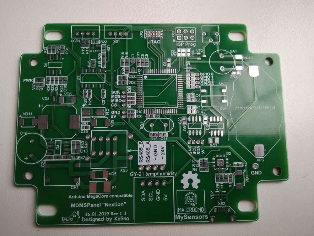
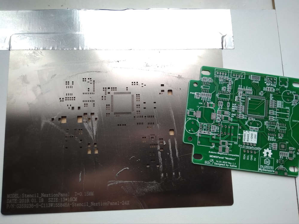
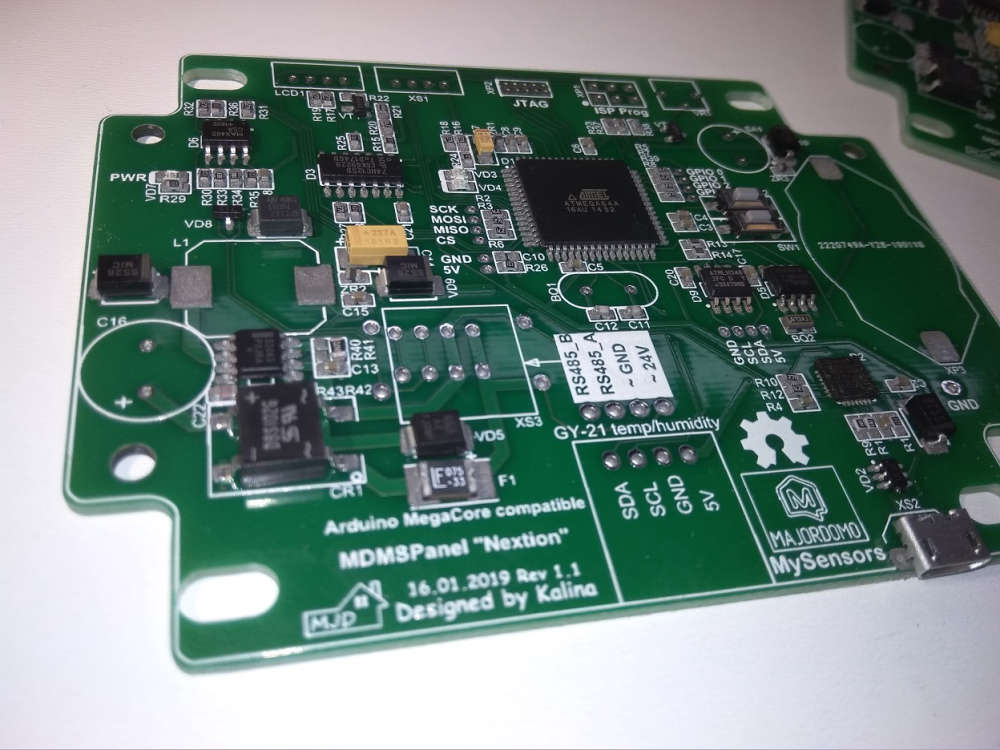
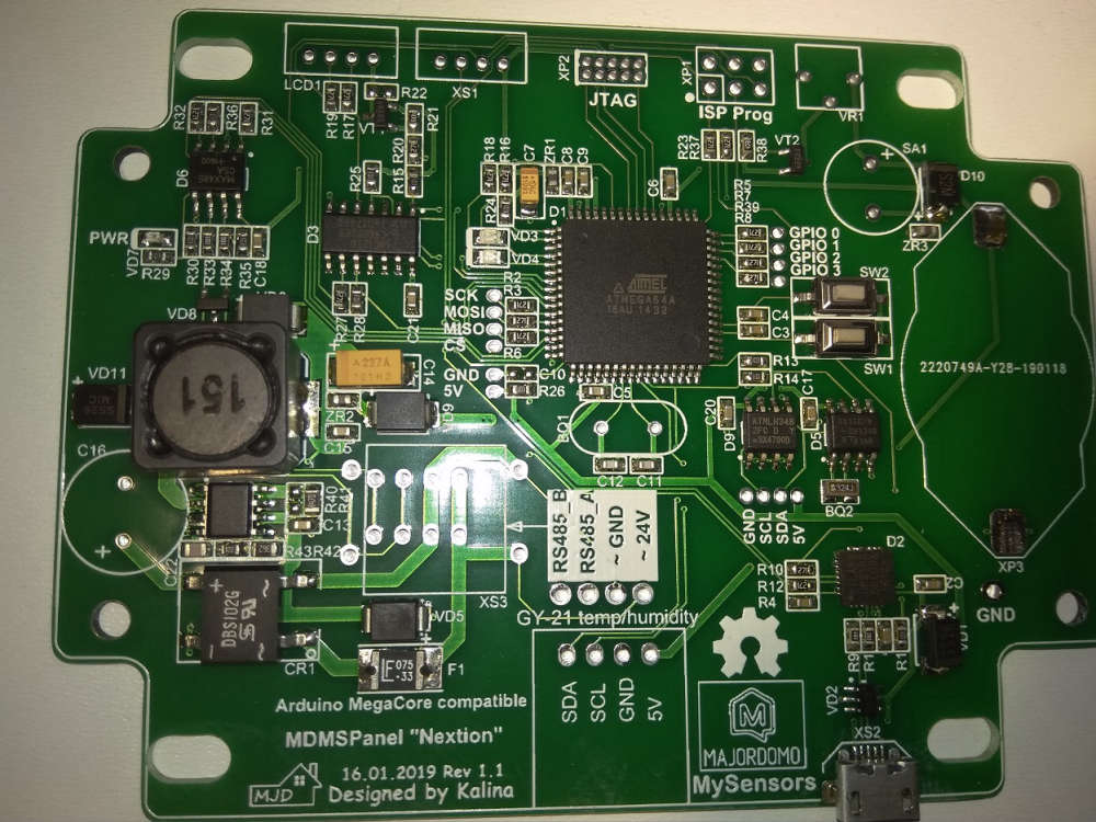
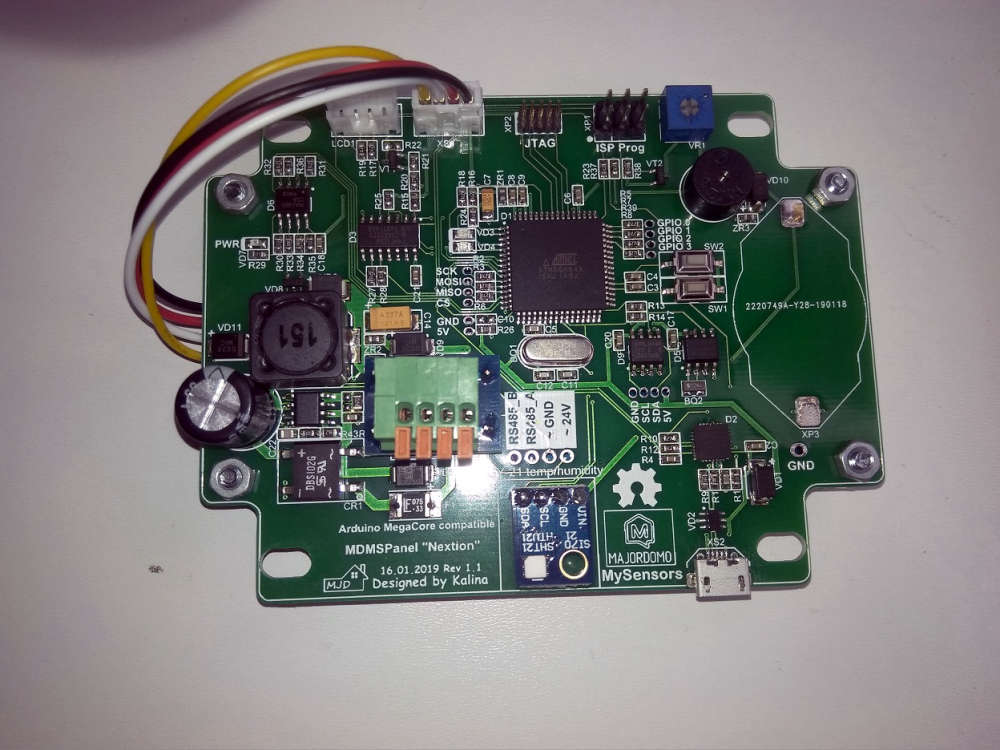
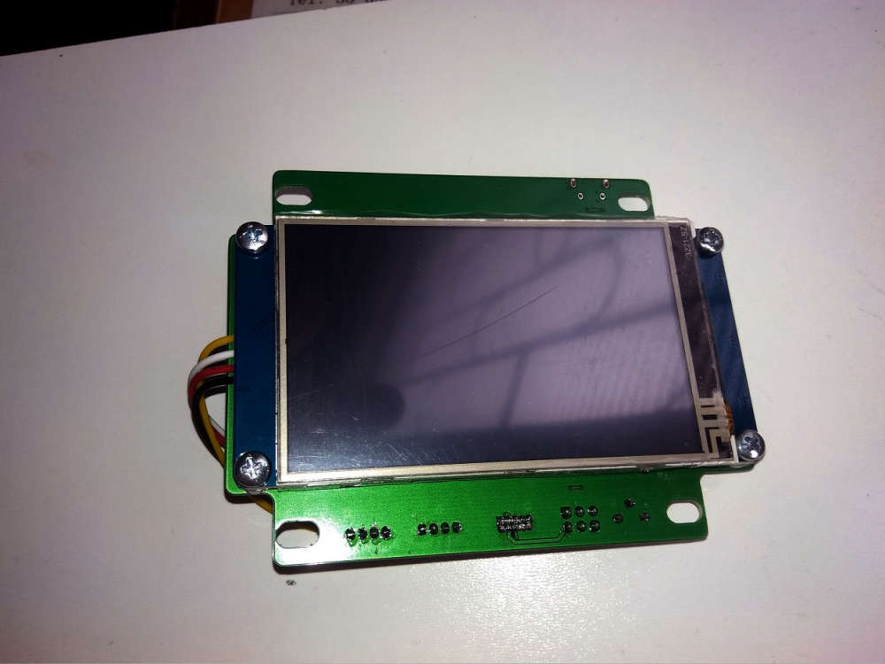
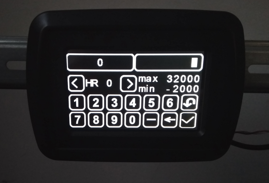
    Some photos of my new device - MDMSPanel "Nextion". I have finished soldering an hour ago)) Next week i will public this project.

    0_1550219059331_NextionPanel_1.jpg 0_1550219064537_NextionPanel_2.jpg 0_1550219068735_NextionPanel_3.jpg 0_1550219072239_NextionPanel_4.jpg 0_1550219076119_NextionPanel_5.jpg 0_1550219079784_NextionPanel_6.jpg 0_1550219083264_NextionPanel_7.jpg


  • @kalina
    Looks good, however due to EMC I strongly recommend to add a GND groundplane on your PCB. I would myself have TOP layer as +DC and BOT layer as GND, this provide less power "sparks" on the tracks and a "capacitor" effect on whole PCB

    https://en.wikipedia.org/wiki/Ground_plane#/media/File:TerraTec_G3_circuit_board_2.jpg

    https://www.quora.com/What-is-the-importance-of-a-ground-plane-of-a-PCB?share=1


  • Mod

    @kalina very cool board. Must be your most advanced MySensors board so far?


  • Hardware Contributor

    @mfalkvidd I would to say what this board is the most necessary for me at the moment. I tired of using various gadgets as a control panels for my nodes. Also, i want to try RS-485 in conjunction with MySensors. Next step is add RS-485 to my MDMSGate....


  • @bjacobse to do proper ground and vcc planes you need a 4-layer PCB. Otherwise you won't get much of a difference in terms of EMI. Another way is to have 2 layer board and to have one layer only for ground plane, but that means you have to do all routing on one side, without making lines across your ground plane. Otherwise you decreasing grounding effect on EMI.
    More on this topic in this free webinar: https://www.signalintegrityjournal.com/events/54-best-iot-board-design-practices-balancing-density-cost-low-power-and-mixed-signal


  • @monte
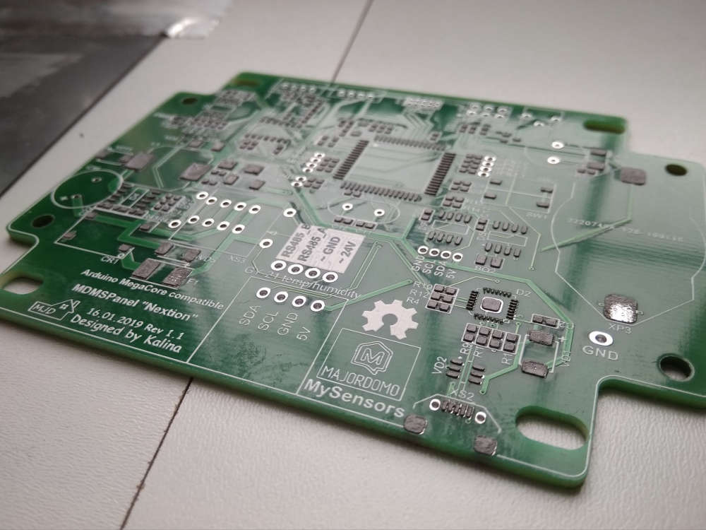
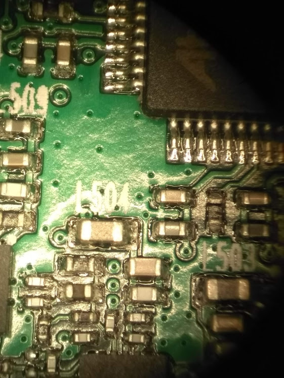
    Well now Kalina already uses 2 layer PCB, so to improve current 2-layer PCB with ground planes are strongly advised.
    Yes 4 layer is naturally much better, but is it needed for a "commodity" device? I think not, and it will increase PCB cost...

    If you don't have a GND and power planes, you will most likely have power spikes when an IC needs current, this will introduce a magnetic field that will "disturb" especially sensitive analogue tracks and clock signals


  • Hardware Contributor

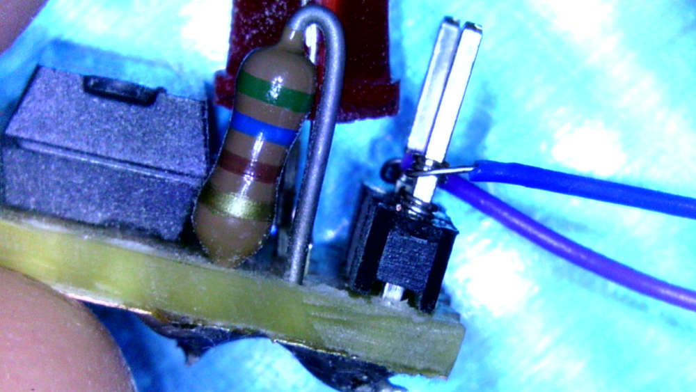
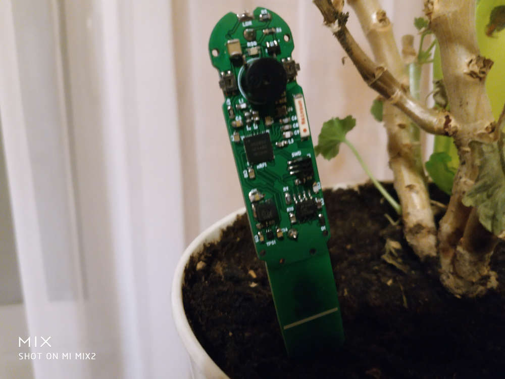
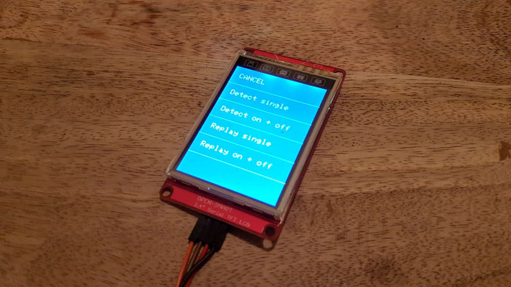
    My actual project is a doorbell sensor with additional temperature and humidity sensors. Tried different ways to detect the ring:

    • hall sensor (failed)
    • microphone (FFT, ongoing research)
    • optocoupler to detect the 12V AC -> favorite solution

    As I was heavy prototyping, I tried wire wrapping and it is fun:
    0_1550390000040_SUNP0002_Moment.jpg


  • @acb Hot air has been used for soldering the board. I have not tried low power as I did not build this board for a battery sensor. My board has got two LEDs - power and another LED connected to D0 so clearly not very low power. I also have a 16Mhz firmware. I did not have any size limitation either. I have one particular node with a few sensors and with signing I cannot upload the sketch onto ATMEGA328P as it is marginally larger. Having said that I have not spent too much time optimising the sketch. I think that refactoring libraries, you are fine with ATMEGA328P in 98% of all MySensors applications.
    BTW - this is not my project. I have followed it https://github.com/peekpt/mightyduino

    Re cost. I stopped Ali shopping for ICs and other sensitive components some time ago after purchasing some fake ATMEGA328P and wasting so many hours trying to troubleshoot it. There is a post about it here on MySensors forum. Ever since I order all components on digi-key. 1284p is priced around $5 + 20% VAT. 328P is priced at $1.2 + VAT. However, I can also buy ATSAMD21 for $2.2 + VAT. Do you see my point? 1284p is extremely expensive and yet it is still 8 bit processor. That's why for me it was a one-off board.

    Re sleeping
    I am using TPL5110 which I built myself (similar to Adafruit one).
    Check out sleeping current:

    alt text

    Sadly, I struggled to get some sensors to sleep properly - probably lack of my programming skills - and with a sleeping current being hundreds of uA, I had to resort to this trick. Most of the time, the node sleeps is disconnected from power by TPL5110 then timer is up and it powers up, sends all sensors readings to the GW and then power gets disconnected to the node, only TPL5110 goes to nA sleep. Perfect!


  • @kalina scene controller? I have almost finished mine on Nextion, but do not have time to tidy things up.


  • Hardware Contributor

    @alexsh1 Yes, it will be a scene controller. I also developed nice enclosure with a magnetic mount. In a few days I will share new photos.


  • @bjacobse but it actually seems that he HAS a ground plane on one side of PCB, if you look closer at the third photo šŸ˜‰


  • @monte I didn't notice this, but you are right, "hidden" LCD šŸ™‚


  • @fotofieber
    Wirewrapping is an "old" and well proven technology, remember to have extra cable in case you need to re-wire your cables. Not so popular by DIY as tools used to be fairly expensive as it was protected by patents...


  • @bjacobse
    Just to add a little more info about adding a GND plane to your PCB
    I work in a electronic company, not doing PCB layout there though.
    but we have a TV adapter which have 2.4GHz transmitter. and this PCB is GND on both sides and with plenty GND via's (all the small holes) to ensure good grounding
    0_1550599901242_pcb_gnd.jpg

    In case you wonder what it is, then it's an Oticon TV adapter 3.0
    Clear Opn pairings with TV Adapter 3.0 ā€“ 00:34
    ā€” Oticon USA, Inc.


  • Plugin Developer

    A picture from the touch screen version of the universal 433Mhz signal cloner.

    0_1550657275800_20190218_220812_resized.jpg

    0_1550657368700_20190218_220931_resized.jpg


  • Hardware Contributor

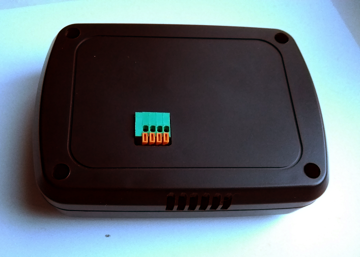
    I have finished an enclosure for the my MDMSPanel "Nextion" today.

    4_1550659232406_Panel_5.png 3_1550659232406_Panel_4.png 2_1550659232405_Panel_3.png 1_1550659232405_Panel_2.png 0_1550659232404_Panel_1.png


  • Plugin Developer

    Wow, very cool! Can you share a bit more about the project? Is it MySensors based? Is there code available? What does the hardware inside look like? What processor is it base on?

    Ah, scrolling up answered some of my questions šŸ™‚


  • Hardware Contributor

    @alowhum Yes of course. I am going to publish this project this week.


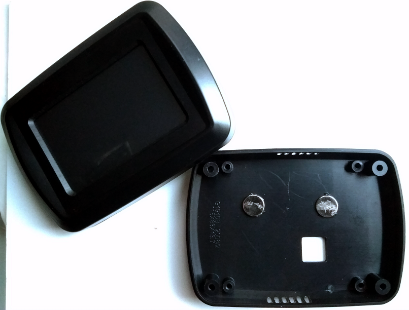
  • @kalina Kudos on the case. Is that a case you designed, or is it a prefab case that you bought somewhere? I am assuming that from the markings inside the case that it is a prefab.I do like the design though and love it's underlying project. Is that just a thermostat, or is it a multi option controller?


  • Hardware Contributor

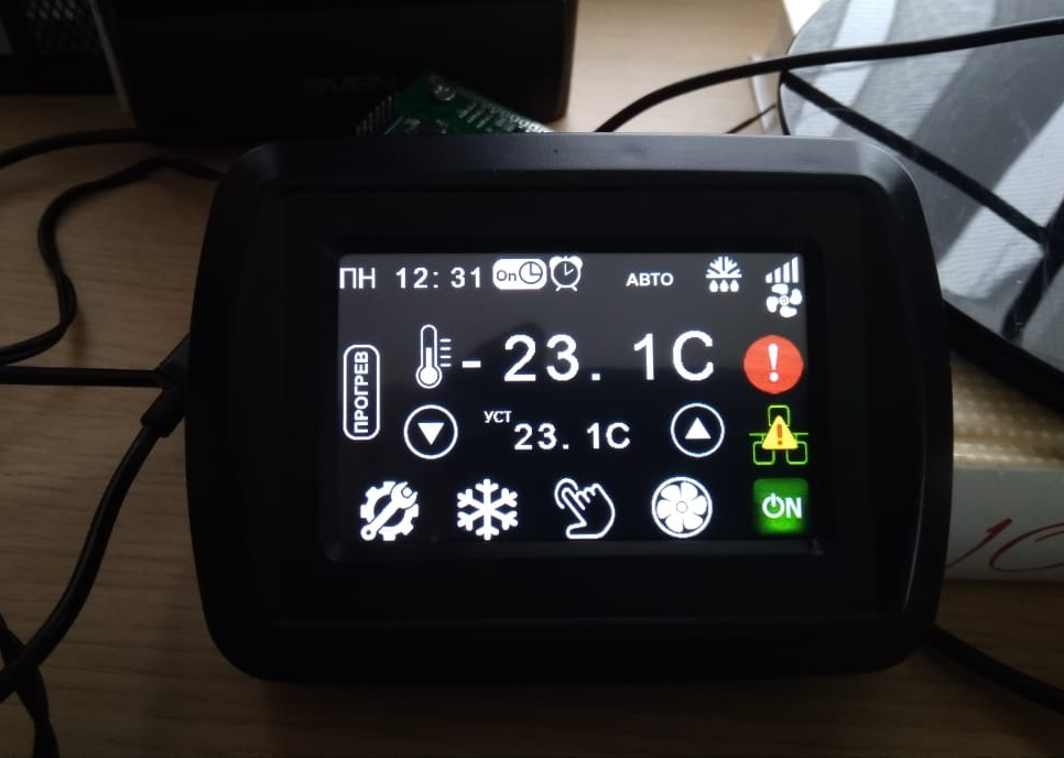
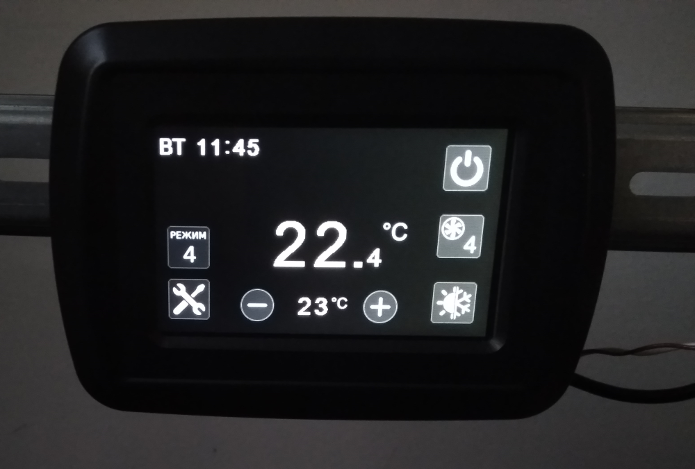
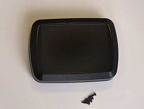
    @dbemowsk Yes, it is a factory case, and before the changing it looked like this :

    0_1550728110717_Enclosure.jpg

    At the moment this is termostat, but I will not limit myself to this)) The purpose of the panel will be determined by the software project loaded into it. I will describe this in more detail when I publish the project.


  • @kalina
    Yes it's very impressing what you have achieved


  • @kalina I like that case design so much that I may design one like it in OpenSCAD and post it on thingiverse.


  • Hardware Contributor

    @bjacobse said in What did you build today (Pictures) ?:

    Yes it's very impressing what you have achieved

    Thanks, the project is published already.

    https://www.openhardware.io/view/676/MDMSPanel-Nextion


  • Hardware Contributor

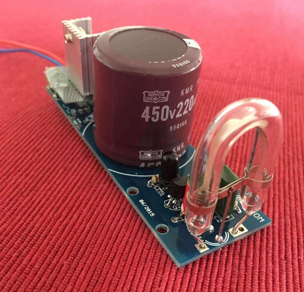
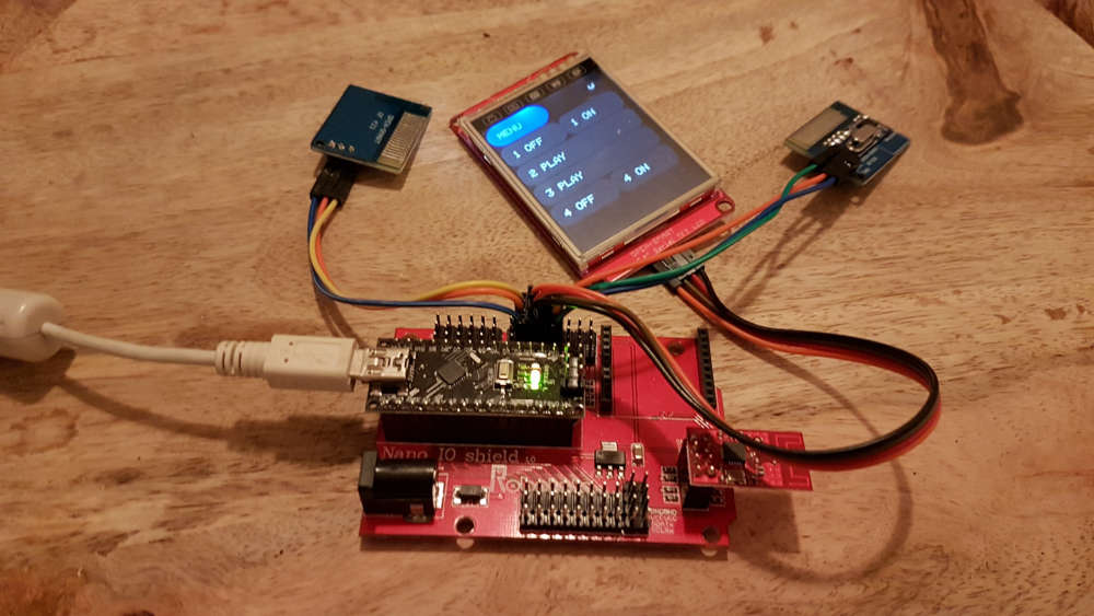
    Building a (xenon) flash to notify alarms. Flashes every 5 seconds if activated.
    0_1551620885559_IMG_3712.JPG


  • Hardware Contributor

    0_1551906897330_IMG_20190306_202143.jpg


  • Hardware Contributor

    0_1551991351537_15519913129101101407969.jpg

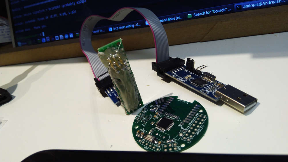
    Today I made a iscp pogo pin adapter... Great for uploading bootloaders.


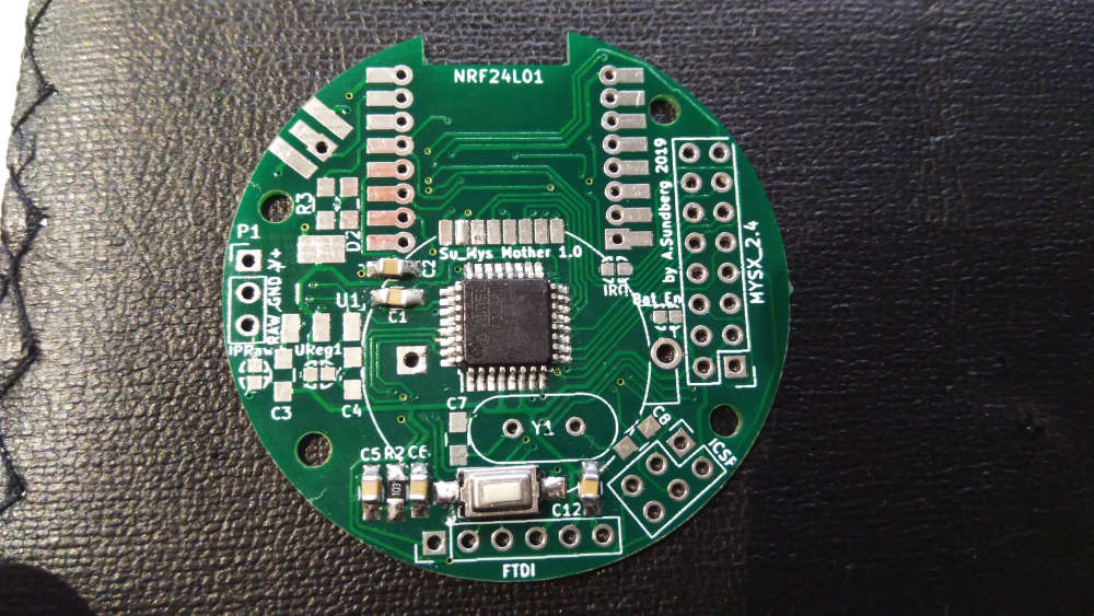
  • Almost finished one of my projects. The test sketch showed that HW works as it should. Now i need to make good software.
    0_1552175238135_IMG_20190310_023119.jpg

    Mysensors Plant Watering Sensor on nRF52832 | not just MeSensors :) ā€“ 00:28
    ā€” Andrew EfektaSB


  • @sundberg84 that board looks nice and crisp šŸ‘


  • After months of slow painstaking work (day job is somewhat busy, o and the kids šŸ˜‰ ) I finally completed my Domoticz server(case) with Dashticz as frontend.

    The Endgame; when my new house is finished every room is monitored for motion, RH and Temperature using my MySensors PCB's. (Jung AS500 Node)

    Everything is monitored using a raspberry with a MySensors serial gateway (NRF52) and an RFLink controller for my KAKU switches.

    To make everything nice and shiny I use Dasticz to interface the data in a proper way using a tablet that somehow will be mounted on a wall or something.

    So far the introduction;
    To put everything away nice and tidy I used a box to install everything using 2 pieces of din-rail.
    It has a 230V inlet that is converted to 5V using an off the shelf (safety sake) MeanWell RS-15-5 converter. This powers everything using a couple of din-Rail terminals.
    0_1552832998737_20190317_135951.jpg

    • Terminal => USB-micro => Raspberry
    • Terminal => just a couple of wires => old nrf52 prototype => FTDI => Raspberry
    • Raspberry => RF-link (ard. Mega +433mhz)

    Since the Raspberry has Wifi no other cable then power is needed to operate

    0_1552833042835_20190317_140232.jpg

    Second part: the 2 screenshots of dasthicsz.
    0_1552832852811_Das1.png
    0_1552832860357_Das2.png

    The best part, it took some work, but the WAF incread big time, because everything looks clean šŸ™‚


  • @omemanti Nice DIN rail enclosure.


  • @dbemowsk

    If someone would be interested:
    Enclosure
    Ard. Mega enclosure
    Raspberry enclosure

    Had to do some modifications for the mega, but the cost of this enclosure was more than worth it.

    Hmz.. normaly don't buy stuff at conrad but apparently they have good prices on cases... šŸ˜


  • @omemanti well...enclosure at a price of 3 raspberry pi zero. Good price indeed šŸ™‚


  • Hardware Contributor

    0_1552926495997_15529264809961412241838.jpg


  • Nothing fancy. Got my new ts100 today and I pre-soldered some V10 easyPCBs with 3.3v Arduino pro minis.
    The iron is pretty good. It is Louis Rossmann approved. Now I need a good 24V power source to drive this thing.

    alt text


  • Hardware Contributor

    Testing a CCS811 CO2 sensor. It seems to use less power then the MH-Z14A I am using now. The CCS811 may even run on battery. I will compare measurements of these two sensors with a Netatmo sensor. The sensors have to burn in for two days bevore I start the comparison.
    0_1554572353955_IMG_3788.JPG
    The CCS811 breakout board I use hast temp, hum and barometer sensors (and the CO2).


  • Hardware Contributor

    @fotofieber said in What did you build today (Pictures) ?:

    Testing a CCS811 CO2 sensor.

    Unfortunately this is not a CO2 sensor. It's only a VOC sensor giving an estimated eCO2 value. It's useful to tell you if your room needs ventilation, but not much more. And as even the VOC part is not calibrated it's only good for relative measurement.
    AFAIK the only similar sensors which are calibrated and give absolute values are SGP30 and BME680.
    If you want to measure CO2 you need a CO2 sensor and it's going to consume a lot of power, at least too much for a battery powered sensor.

    [edit] there's also the MiCS-VZ-89TE TVOC sensor, they claim to have a curve of eCO2 not too far from NDIR sensor in their datasheet. But that datasheet is strangely poor in details, they didn't even put any electrical characteristics...
    https://sgx.cdistore.com/datasheets/sgx/MiCS-VZ-89TE_V1.0.pdf


  • My battery operated mini touch switch

    1_1554642160825_photo_2019-04-07_13-58-03.jpg 0_1554642160824_photo_2019-04-07_13-58-02.jpg


  • 1_1554642422327_photo_2019-04-05_21-32-08.jpg 0_1554642422326_photo_2019-04-05_21-32-08 (2).jpg


  • Hardware Contributor

    I don't think I ever managed to get it right the first revision.

    0_1554644735090_1554644713534396819827.jpg


  • Hardware Contributor

    But it's something...

    0_1554651767460_15546517582521430623468.jpg


  • Hardware Contributor

    @sundberg84 you should print the board on paper, stick it on a piece cardboard and cut. Then check if size is good, you can even put the "big" components on it by sticking the pins through the cardboard to make sure you'll have enough space.


  • Hardware Contributor

    @nca78 great tip! But it's more common it's a schematic or footprint error. The outline "should" be the easy part even if I messed up.


  • Hardware Contributor

    @nca78 said in What did you build today (Pictures) ?:

    @fotofieber said in What did you build today (Pictures) ?:

    Testing a CCS811 CO2 sensor.

    Unfortunately this is not a CO2 sensor. It's only a VOC sensor giving an estimated eCO2 value. It's useful to tell you if your room needs ventilation, but not much more. And as even the VOC part is not calibrated it's only good for relative measurement.

    My tests will show, how far away I am with this sensor in my indoor usage scenario.

    My Netatmo sensors claim to measure CO2 and are battery powered. They seem to calibrate themselves to the lowest level they measure in 24 hours. This behaviour seems to be similar with the CCS811. The Netatmo sensors seem quite close to my MH-Z14A.

    In the datasheet for the CCS811 I have read, that you can't use them in your green house, because of its self calibration. Netatmo may have the same restriction too.

    AFAIK the only similar sensors which are calibrated and give absolute values are SGP30 and BME680.

    I have ordered a SGP30 some days ago and will test it too. The BME680 needs binary code linked which is a no go for me. (As a gift I would take it into my test setup. šŸ™‚ )

    If you want to measure CO2 you need a CO2 sensor and it's going to consume a lot of power, at least too much for a battery powered sensor.

    The problem with high power sensors is, that they produce heat, which can make your temperature measurements unusable. šŸ˜ž

    As my CO2 sensors have a color led to show air quality, they are mains powered anyway.

    [edit] there's also the MiCS-VZ-89TE TVOC sensor, they claim to have a curve of eCO2 not too far from NDIR sensor in their datasheet. But that datasheet is strangely poor in details, they didn't even put any electrical characteristics...
    https://sgx.cdistore.com/datasheets/sgx/MiCS-VZ-89TE_V1.0.pdf

    Thank you for the link. I have ordered one for my test setup. They are really expensive, about twice the price of the MH-Z14A, the SGP30 or the CCS811.

    Other CO2 sensors I should use in my test setup?

    I like the MH-Z14A and depending on my tests may stay with them.

    EDIT: ordered a MHZ-19 for the tests


  • Hardware Contributor

    @fotofieber said in What did you build today (Pictures) ?:

    EDIT: ordered a MHZ-19 for the tests

    Make sure you order a MHZ-19B, it uses less power and has fixed an autocalibration problem.
    SenseAir S8 has a better calibration process using several days, so if you don't ventilate your room during 24h it will not use a wrong reference level and report wrong values.

    And about BME680 there are boards on AliExpress with included STM32 Cortex M0+, basically it's the same than the MiCS-VZ-89. Search for GY-MCU680V1.


  • Hardware Contributor

    @nca78 said in What did you build today (Pictures) ?:

    And about BME680 there are boards on AliExpress with included STM32 Cortex M0+, basically it's the same than the MiCS-VZ-89. Search for GY-MCU680V1.

    Thx, ordered one on aliexpress. Hope I have time to test when they arrive... šŸ™‚
    EDIT: first results, hope CCS811 will calibrate better in the next two days
    0_1554786685400_co2-sensor-comparison.png


  • Admin

    @berkseo nice! What did you use for the capacitive sensor? MPR121?


  • Hardware Contributor

    @petewill said in What did you build today (Pictures) ?:

    @berkseo nice! What did you use for the capacitive sensor? MPR121?

    TTP223s in top left and top right corners šŸ˜‰

    @berkseo I'm curious about that, why not use the capacitive touch function of the NRF52832 ?


  • @nca78 said in What did you build today (Pictures) ?:

    TTP223s in top left and top right corners

    yep šŸ™‚


  • @nca78 said in What did you build today (Pictures) ?:

    I'm curious about that, why not use the capacitive touch function of the NRF52832 ?

    Ttp223 chips suit me. Very stable stuff. When I tried to do it on amtel328, these mcu also had this feature (almost all mcu have this feature). But it was not very stable. I'm not sure that a stable device using the mcu 52832 would be possible. If there is an example of a stable software implementation, I would be happy to test it, and then it would be clear to do it without external capacitive chips or not.


  • Mod

    My new workbench is coming along nicely.
    0_1555441622135_533CC67F-75F9-4E27-B9BE-15796197EC60.jpeg


  • Mod

    Top shelf is for network stuff
    0_1555446671813_IMG_1208_edit.jpg


  • @mfalkvidd good job


  • Continuing along the theme of one of my last projects, I built a nRF52832 into a 328p Pro Mini footprint. Made two versions: One with some edge SMA or U.Fl pads and another with a PCB trace antenna:

    0_1555494186797_Pro Mini 328p vs. Pro Mini nRF52.jpg

    0_1555494248417_Pro Mini 328p vs Pro Mini nRF52.jpg

    I wanted to start getting into using 32-bit microcontrollers (ARM Cortex varieties like nRF5x, SAMDs, STMs, etc.) for some more complex HA and other electronics projects and am trying to ease the learning curve from all my 8-bit ATMEGA experience.

    Keeping the 328p pin-compatible footprint and PCB size means I can still reuse most of my other Pro Mini project boards to get going. An added bonus is the nRF52's ability to remap (almost) any pins, which will no doubt come in handy.

    Theyā€™re both two layer boards and I get pretty decent range out of the PCB trace antenna - ever so slightly better RSSI than EByteā€™s E73-2G4M04S1B, which was surprising since I didnā€™t really do anything different (that Iā€™m aware of) and their module is shielded too.

    Since thereā€™s no need for a separate nRF24 board and other associated components, like external SRAM or ATSHA, itā€™ll possibly save me a few $ too! Power pins next to the (remappable) I2C pins make some of the sensor modules (like SI7021) pluggable.

    I also gain 16x the program memory (512K vs. 32K) and 8x the speed (64MHz vs. 8MHz) which is no small increment!

    Some of the project boards I have made use of the Pro Mini 328pā€™s FTDI pins, so I added a few components to enable the use of an FTDI programmer with custom DFU serial bootloader.

    0_1555494282393_FTDI DFU Serial Bootloader - Pro Mini nRF52.jpg

    Basically, a DTR pin toggle from the FTDI will reset the nRF52 into a state where itā€™ll briefly listen for a new program - similar to Adafruitā€™s Feather. You can also force that state for a longer period with a combination button press like Nordic and SparkFunā€™s development boards.

    Iā€™m unfamiliar with SWD/JTAG programming/debugging and all things GDB/OCD, so I built myself a black magic probe out of a STM32 blue pill and am going to have a play with all of that, along with VS Code and PlatformIO and probably one or two others.

    MySensors nRF52 support worked out of the box (!) - so a huge thanks to all the hard work of the folks round here for getting that up and running. If thereā€™s anything I can help with there, please let me know and if Iā€™m able, Iā€™ll try to take a stab at it (OTA maybe?). Like I said, Iā€™ve got quite a steep learning curve here though.

    On the low power end, I added the DCDC components Nordic recommend too and managed to get the MySensors smartSleep() current down to around 0.7uA - as per the datasheet, I think. However, I found that with a couple more code tweaks and grounding the SWDCLK, I would get into the nA region. This seems a bit out of spec to me and perhaps itā€™s just a measuring error, but it was repeatable and the board still happily sending data/heartbeat again each time it woke up. (Itā€™s fluctuating around 1.6nA below - no sensors connected though, but itā€™s a startā€¦)

    0_1555494689754_1.6nA Fluctuating Sleep Current - SWDCLK to GND - Pro Mini nRF52.JPG

    One other project in the back of my mind is using this board as the basis for a quadcopter, but thatā€™ll probably have to wait until the summer holidaysā€¦!


  • @acb Nice! I have serious board envy. I really like that clip on programmer too.


  • @acb have you written a bootloader yourself, or found already available? Can you tell more about it and a board you using to connect nrf52 to FTDI?
    Nice work!


  • Well,in my case, I mounted and tried to fix bugs in my very first design. This is supposed to be a castelizable Sensebender compatible node, embedding NRF24L01+, LED, Temp/Humi/Press sensor, Memory, crypto, with most of the IO exposed. The updated design is online, but still work in progress. 0_1555517692648_IMG_20190417_180651748.jpg
    project on OpenHardware


  • @acb Wow. Awesome


  • My light sensor on the window. Will work as a slave device for the curtain controller.
    0_1555632724931_WhatsApp Image 2019-04-19 at 02.39.39.jpg

    Mysensors Light sensor (LUX) on nRF52832 | First HW&SW test ā€“ 01:46
    ā€” Andrew EfektaSB


  • Hardware Contributor

    New gateway going live and migrating slowly from Domoticz to Homeassistant. At least to try it.

    0_1555657543370_IMG_20190419_090304.jpg


  • @nagelc Thanks! The clip on programmer is one-part Adafruitā€™s FTDI ā€œFiddyā€ from here, and one-part SparkFunā€™s old (retired?) 3.3 or 5v selectable FTDI programmer with a custom 3D printed enclosure.

    I plan to modify the ā€œFiddyā€ design a bit as there were some elements of it that Iā€™ve found a bit frustrating. However, YMMV. Gotta love pogo pins for programming thoughā€¦

    Re: Board envy. Really? Well, if you like, I could do what I did on my last project - which was selling the leftovers. At the moment, I always make more than I need, for testing and some much needed practice with the smaller 0402s. Just send me a chat message if you (or anyone else?) are interested.


  • @monte Re: FTDI Boards & Bootloaders.

    I didnā€™t write the bootloader myself from scratch, but modified and combined various elements from Nordicā€™s SDK v11 example, SparkFunā€™s development version and Adafruitā€™s Feather version.

    It was quite a nice learning experience of hacking in bootloader land and dealing with event-driven architectures without any low level debugging skills (yet!) - thatā€™s why Iā€™m now trying to get into SWD/JTAG debugging to make things like this easier.

    I certainly donā€™t understand everything thatā€™s going on, but ā€œlooselyā€ from what I can figure out, it uses Nordicā€™s proprietary SoftDevice (S132) combined with some custom bootloader code to boot into a predefined state, where itā€™ll wait for new ā€œimageā€ either over a serial or bluetooth connection.

    The new ā€œimageā€ can be either your regular sketch-type code (referred to as the ā€œapplicationā€), a new SoftDevice (S212, S332, etc.) and/or even a new bootloader.

    Once the new ā€œimageā€ is received and validated by the (existing) bootloader, it is copied to replace the existing ā€œimageā€ parts where necessary and the chip is reset.

    Nordicā€™s pc-nrfutil command line utility handles interfacing with any standard FTDI board over a COM port (mine is an old SparkFun, but any should work) to perform the upload.

    In SDK11, there isnā€™t much in the way of safeguards, but in SDK15 there are things like cryptographic signing, custom initialization packets and protocol buffers, etc.

    I did have to make one tweak to the nrfutil Python code, to make it wait a little longer after opening the COM port before sending the DFU initialization packet. This might be unnecessary with optimized bootloader code, I donā€™t know, since the nRF52832 boots pretty quickly.

    I could go on, but Iā€™m still learning myself, and so if you or anyone else has any other questions, comments, suggestions, etc., perhaps we better move them to a new discussion thread? (Just tag me in so I see itā€¦)

    Thanks for your interest though!


  • Very nice @Fanfan!

    Love the power protections - those would have saved me a few nRF24s in the past!

    How have you found the ceramic antennas?

    Iā€™ve been wondering whether to add pads to mine for experimenting...


  • Thanks @berkseo!

    Have been enjoying your work with nRF52 designs.

    Also on my list is trying the built-in capacitive touch capabilities of the chip.

    I can @ you if I get anywhere with it - might come in handy for your capacitive touch glass mini switch to save you a few components?


  • @acb Of course!!!, ttp 223 gives a reliable result, but if there is an opportunity to make a stable implementation based on the chip itself, then definitely it needs to be done. I would appreciate any help and advice.


  • @acb we can continue discussion in this thread, If you want: https://forum.mysensors.org/topic/6961/nrf5-action/

    So as I understand for now you are using native SDK and not using Arduino and mysensors? As far as I know arduino's core for nrf5 has no support for bootloaders, and mysensors conflicts even with softdevice being present on a chip. And it seems that sandeepmistry (author of the core) isn't going to invest his time into writing bootloader and can't use nordic's one because of license. I would like to have a bootloader solely for bluetooth OTA programming for projects beside mysensors. Maybe you could share your work, and/or write some kind of brief tutorial on where to start working on this subject maybe to avoid problems you have already solved? Anyway, great work from you, hope someday we will have mysensors on nrf52 with working OTA.


  • well this is my project , right now im using 2 arduino nano with ethernet shield to read 3 lines Voltage on a delta instalation , 3 current sensors of 300amps for a motor , and 1 water pressure ,
    all conected to a raspberry pi with domoticz
    0_1555866423061_IMG_20190416_160915041_BURST000_COVER_TOP.jpg

    but yesterday i decide to change all , instead of 2 uno i will use a pro mini with a nrf24
    so i desing two pcb
    0_1555866610375_downImg.png

    0_1555866627272_downImg2.png

    some code

    #define MY_NODE_ID 100
    #define MY_DEBUG
    #define MY_RADIO_NRF24
    
    #include <SPI.h>
    #include <MySensors.h>  
    
    
    #define CHILD_ID_VOLT_1 1
    #define CHILD_ID_VOLT_2 2
    #define CHILD_ID_VOLT_3 3
    
    #define CHILD_ID_CURRENT_1 4
    #define CHILD_ID_CURRENT_2 5
    #define CHILD_ID_CURRENT_3 6
    
    #define CHILD_ID_PRESION 7
    
    #define VOLT_SENSOR_ANALOG_PIN_1 0
    #define VOLT_SENSOR_ANALOG_PIN_2 1
    #define VOLT_SENSOR_ANALOG_PIN_3 2
    
    #define CURRENT_SENSOR_ANALOG_PIN_1 3
    #define CURRENT_SENSOR_ANALOG_PIN_2 4
    #define CURRENT_SENSOR_ANALOG_PIN_3 5
    
    
    #define PressPin      A6 


    unsigned long SLEEP_TIME = 20000; // Sleep time between reads (in milliseconds)
    
    MyMessage msg(CHILD_ID_VOLT_1, V_VOLTAGE);
    MyMessage msg2(CHILD_ID_VOLT_2, V_VOLTAGE);
    MyMessage msg3(CHILD_ID_VOLT_3, V_VOLTAGE);
    
    MyMessage msg4(CHILD_ID_CURRENT_1, V_CURRENT);
    MyMessage msg5(CHILD_ID_CURRENT_2, V_CURRENT);
    MyMessage msg6(CHILD_ID_CURRENT_3, V_CURRENT);
    
    MyMessage pressureMsg(CHILD_ID_PRESION, V_PRESSURE);
    
    float lastVolt1;
    float lastVolt2;
    float lastVolt3;
    
    float lastCurrent1;
    float lastCurrent2;
    float lastCurrent3;
    
    float lastPresion;
    
    
    int pressure = 0;
    float PSI = 0;
    float PSI_CAL = 2.0;            // Calibration of sensor
    int PSImsb = 0;
    int PSIr = 0;


    void before() {
    
    }
    
    
    void presentation()
    {
     sendSketchInfo("Multisensor", "1.7");  // Send the sketch version information to the gateway and Controller
     present(CHILD_ID_VOLT_1, S_MULTIMETER);   // Register this device as power sensor
     present(CHILD_ID_VOLT_2, S_MULTIMETER);   // Register this device as power sensor
     present(CHILD_ID_VOLT_3, S_MULTIMETER);   // Register this device as power sensor
    
     present(CHILD_ID_CURRENT_1, S_MULTIMETER);   // Register this device as power sensor
     present(CHILD_ID_CURRENT_2, S_MULTIMETER);   // Register this device as power sensor
     present(CHILD_ID_CURRENT_3, S_MULTIMETER);   // Register this device as power sensor
    
     present(CHILD_ID_PRESION, S_WATER);   // Register this device as power sensor
     
    }
    
    
    void setup()  
    { 
    
    }
    
    void loop()      
    {     
     int Voltaje1 = analogRead(A0);
     int Voltaje2 = analogRead(A1);
     int Voltaje3 = analogRead(A2);
    
     int Corriente1 = analogRead(A3);
     int Corriente2 = analogRead(A4);
     int Corriente3 = analogRead(A5);


     float VoltLevel1 = map(Voltaje1,0,1023,0,500);
     float VoltLevel2 = map(Voltaje2,0,1023,0,500);
     float VoltLevel3 = map(Voltaje3,0,1023,0,500);
    
     float CorrienteLevel1 = map(Corriente1,0,1023,0,200);
     float CorrienteLevel2 = map(Corriente2,0,1023,0,200);
     float CorrienteLevel3 = map(Corriente3,0,1023,0,200);
    
     
     Serial.print("Voltaje L1: ");
     Serial.println(VoltLevel1);
     Serial.print("Voltaje L2: ");
     Serial.println(VoltLevel2);
     Serial.print("Voltaje L3: ");
     Serial.println(VoltLevel3);
    
    
     Serial.print("Corriente L1: ");
     Serial.println(CorrienteLevel1);
     Serial.print("Corriente L2: ");
     Serial.println(CorrienteLevel2);
     Serial.print("Corriente L3: ");
     Serial.println(CorrienteLevel3);
    
     //sensor de voltaje
     if (VoltLevel1 != lastVolt1) {
         send(msg.set(VoltLevel1, 1));
         lastVolt1 = VoltLevel1;
     }
    
       if (VoltLevel2 != lastVolt2) {
         send(msg2.set(VoltLevel2, 1));
         lastVolt2 = VoltLevel2;
     }
       if (VoltLevel3 != lastVolt3) {
         send(msg3.set(VoltLevel3, 1));
         lastVolt3 = VoltLevel3;
     }
    
    
    //sensor de corriente
       if (CorrienteLevel1 != lastCurrent1) {
         send(msg4.set(CorrienteLevel1, 1));
         lastCurrent1 = CorrienteLevel1;
     }
         if (CorrienteLevel2 != lastCurrent2) {
         send(msg5.set(CorrienteLevel2, 1));
         lastCurrent2 = CorrienteLevel2;
     }
         if (CorrienteLevel3 != lastCurrent3) {
         send(msg6.set(CorrienteLevel3, 1));
         lastCurrent3 = CorrienteLevel3;
     }
    
    /* ************************************************ */
       pressure  = analogRead    (PressPin) ;        // junk read
       wait(25);
       
    /* ā€¢ Output: 0.5V ā€“ 4.5V linear voltage output. 0 psi outputs 0.5V, 50 psi outputs 2.5V, 100 psi outputs 4.5V 
       0   psi = .33v after scalling 5.0v to 3.3v
       50  psi = 1.65v
       100 psi = 2.97v
    
       3.3v/1024 = .0032266 volt per bit
    */
       pressure  = analogRead    (PressPin) ;
    
       if (pressure < 106) pressure = 106;         // this is minimum of .5v
       PSI = (pressure - 106 ) * .1246;            // where did we get this?? was .119904
       PSI = PSI + PSI_CAL;                        // adjustment
       
       PSImsb = PSI * 100;
       PSIr = PSImsb % 100;
       
    
       send(pressureMsg.set(PSI, 2));            // Send water pressure to gateway
    
       Serial.print("Presion: ");
       Serial.println(PSI);
       
       wait(200);
       
        // end of if (SLEEP_MODE || (cu
    
     
     sleep(SLEEP_TIME);
    }
    

    havent tested with sensors yet

    but looks good so far
    0_1555866800921_AnotaciĆ³n 2019-04-21 121255.jpg


Log in to reply
 

Suggested Topics

  • 4
  • 1
  • 274
  • 2
  • 14
  • 5

25
Online

11.2k
Users

11.1k
Topics

112.5k
Posts