nRF24L01+ Communication Failure: Root Cause and “Solution”

-
Project Background
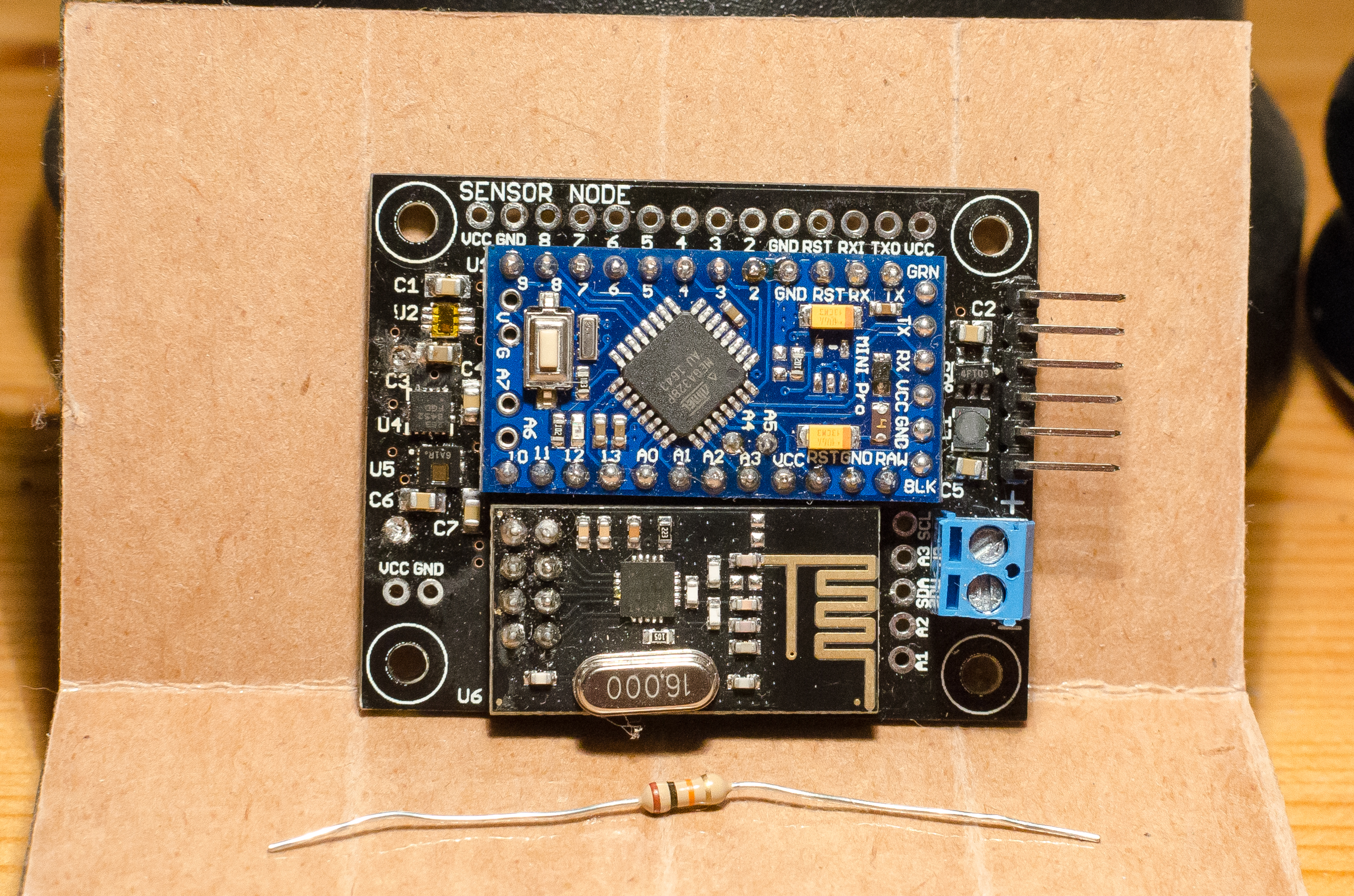
First, some background information on the project. We had prototyped an arduino and nRF24L01+ based sensor board using mysensors and home assistant. The main goal of this board was whole home temperature, humidity, and light level monitoring. The prototype was built from stand alone protoboards, breadboards, wires, etc. It worked great, so we decided to make a custom PCB that would have a socket for the arduino pro mini, a socket for the nRF24L01+ boards, and all of the other circuitry (sensors, power supply, etc).
Image 1: Sensor Board! (Resistor for scale)

Problem
After building up a number of the “New and Improved!” custom PCBs, we noticed that some of them just didn’t work very well. We could read the data from all the sensors via the arduino, but they would fail in one of a few ways:
- Not present with the gateway / Nothing seemingly happens.
- Present but have terrible “message loss”. The original behavior was intermittent updates from the sensors board. To determine our “message loss” we created a debug program that would send a finite number of messages from the sensor board with an ack request and wait for the ack with a time out. The final “message loss” was (number of messages sent ) - (number of messages ack’d).
Initial observations and debugging (in no particular order of desperation).
- More bulk capacitance on the nRF24L01+ board. No luck. (BUT THE FORUMS PROMISED)
- Changing power source (Batteries, Benchtop, etc) didn’t change behavior.
- Changing the nRF24L01+ on our gateway (Raspberry Pi) didn’t change behavior.
- A “problem” sensor board got “better” when we swapped out the nRF24L01+ board. (AHA! It must be the questionably authentic nRF24L01+ boards we ordered). So, we built a sensor board with a header socket so we could quickly screen/test all of our nRF24L01+ boards. This was ineffective and led to confusion (Wait, I thought you said this nRF24L01+ board worked?) as some nRF24L01+ boards worked in the screening unit, but then didn’t work in their final sensor board.
- Changing distance between sensor boards and gateway didn’t change anything in a meaningful or coherent way.
- Accidentally holding our thumb on the antenna changed the behavior. (Hey, wait, what just happened? It’s working! Wait.. no it isn't’.. What?)
- Changing the data (symbol) rate of the nRF24L01+ board changed the behavior, but didn’t fix anything.
- Changing the SPI speed also changed the behavior, but didn’t fix anything.
- Changing the channel on the nRF24L01+ board helped at one person’s house but not other project member’s houses.
- Manipulate ground planes on sensor board near antenna. (dremeled away).
- Using the previously mentioned sensor board with a header socket, we observed that almost any nRF24L01+ board worked when cabled (~6 inches) rather than directly plugging into the sensor board. (BUT WHY?????)
{A year, a kid, and job changes later}
Eventually, we decided the project had languished long enough. Enough sleep had been lost! We were going to figure out this problem!
How
Throwing stuff at the wall to see what stuck wasn't working, so we decided we needed to get serious and capture the wireless data. We borrowed a software defined radio (SDR) to capture the 2.4GHz spectrum with the intent of first demodulating the signal to see if that showed the smoking gun (It did but we didn't realize it at the time).
Image 2: Demodulated Signal (Hey, that looks like a digital signal!)

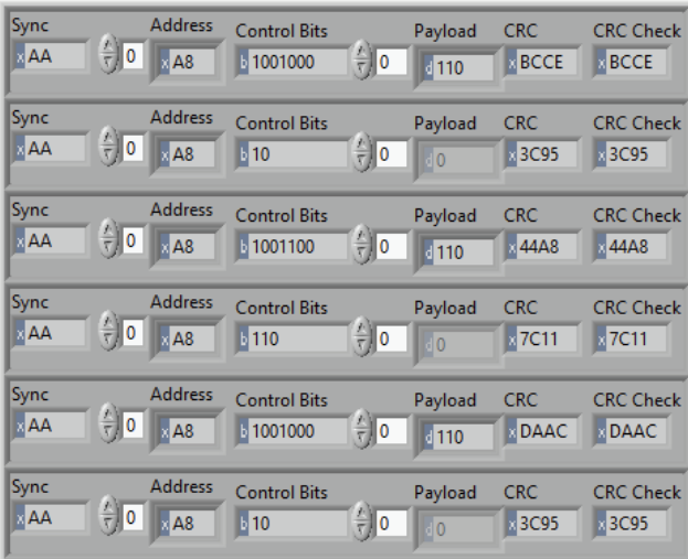
Now that we can see the data to train on, we can decode the nRF24L01+ packet to see what’s going on. Specifically, the goal was to see if a packet was “good” or “bad” and our criteria for a “Good” packet was the Cyclic Redundancy Check (CRC) passing. (See image below).
Image 3: Decoded NRF24L01+ Packet with CRC Check.
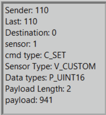
Full of excitement and curiosity, we wielded our newfound RF power to decode the MySensors Payload as well (see Image 4 below) This didn’t prove to be very helpful for debug purposes, but it was interesting.
Image 4: Decoded Mysensors Payload
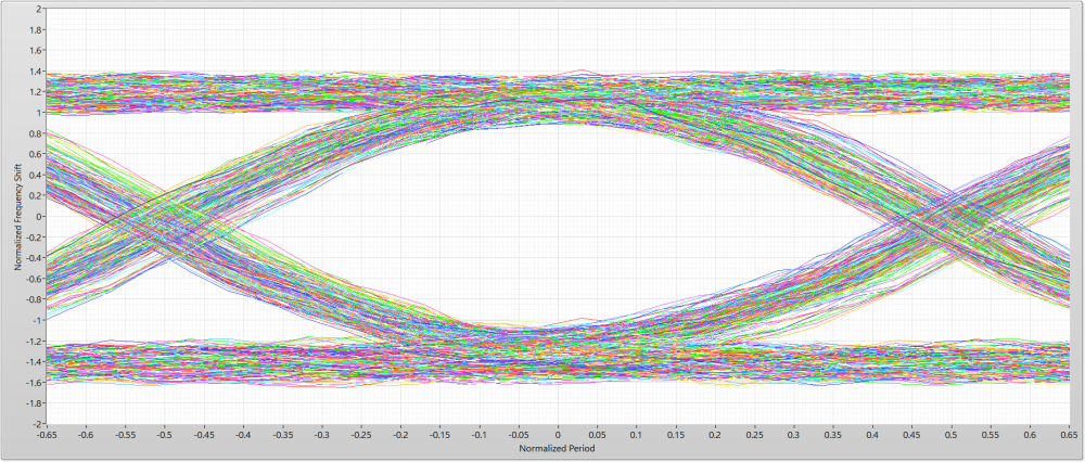
Now that we can see “passing” and “failing” packets, we know we are on the right track. However, we need to measure the transmission “quality” beyond just pass/fail. Since the transmission is just binary data (using Frequency Modulation) we can parse the data to assemble the data Eye pattern (Image 5 below).
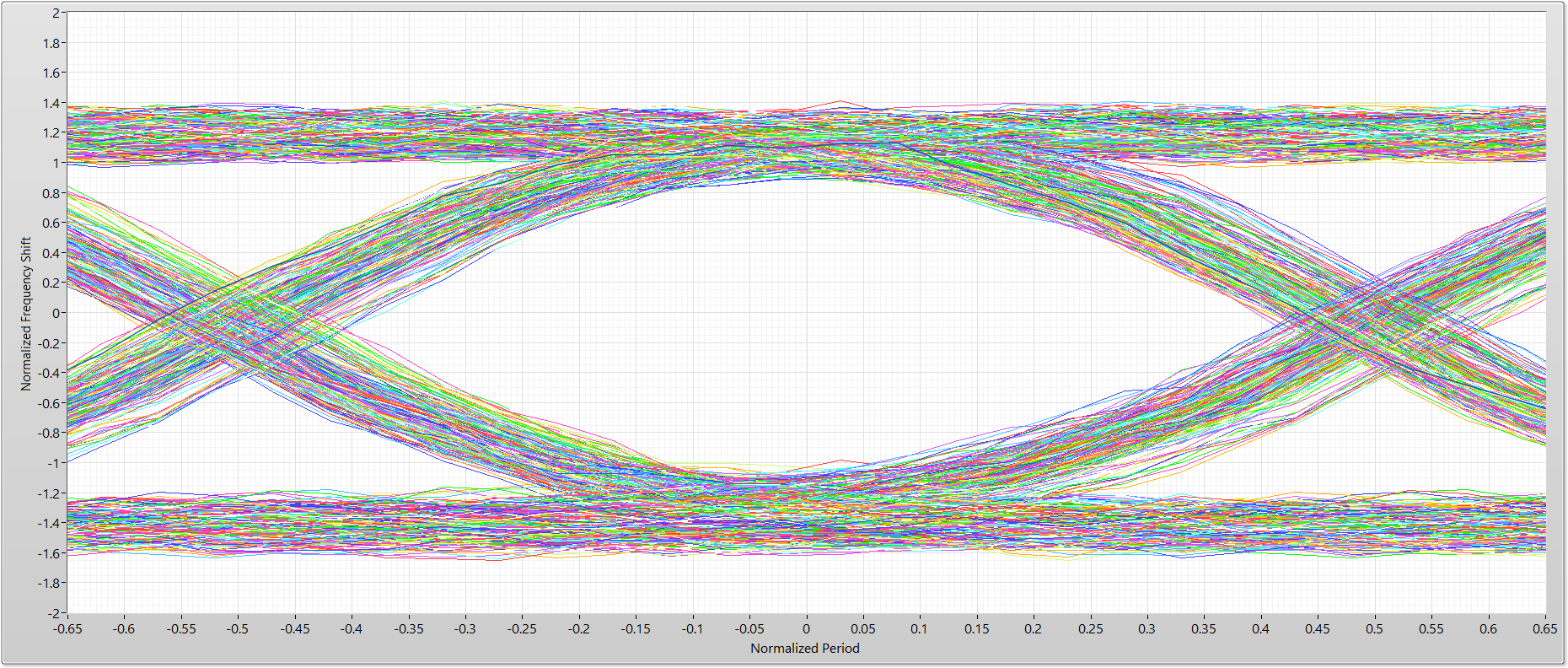
Image 5: Impressively “Bad” data Eye pattern
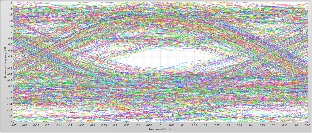
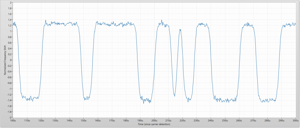
I think I found the problem… But what is causing the Eye to close (good data Eye patterns are wide open in the middle)? Also, sometimes I get really good looking data Eyes! What is going on?!? Let’s have a closer look at a bad transmission. Images 6 and 7, shown below, are single transmissions taken from the multiple transmissions, previously shown in image 2.
Image 6: A closer look at a single “bad” demodulated transmission (Wow, that’s bad!)
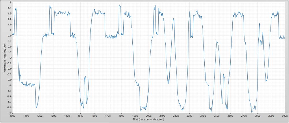
Image 7: A closer look at a single “good” demodulated transmission (That looks perfect! How is this the same board?)
Comparing Images 6 and 7 is very interesting, we might be looking at the root cause here. The bad transmission looks like it has an “other” digital signal riding on top of it. What is going on during the nRF24L01+ transmission?
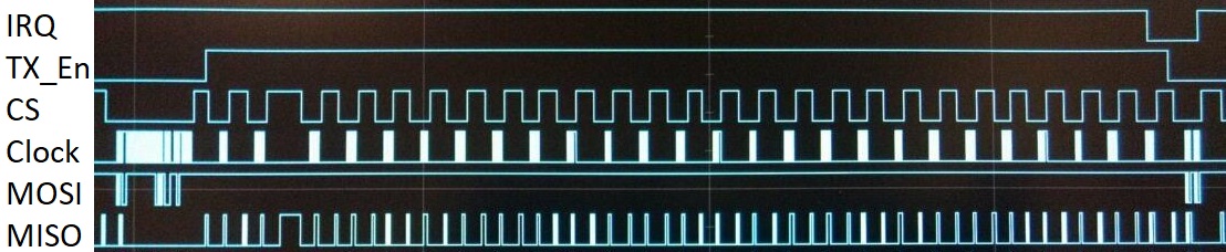
We decided to grab a bus analyzer and record communication on the SPI bus during a transmission (see Image 8 below).
Image 8: A Bus Analyzer capture during transmission (Wait a minute! That looks familiar!)

It seems strange that the SPI bus is constantly active during transmission. What is MySensors doing? Grab the shovel...
Digging into the RF24.cpp file shows the RF24_getStatus() function called continuously at line 326. This pumps the SPI interface (sends 0xFF) to read the status register of the nRF24L01+ and see if the transmission is complete.
A snippet of code from Github (“MySensors\hal\transport\driver\RF24.cpp”) shown below starting at line number 321
Code Snippet 1
// go, TX starts after ~10us, CE high also enables PA+LNA on supported HW
	RF24_ce(HIGH);
	// timeout counter to detect HW issues
	uint16_t timeout = 0xFFFF;
	do {
		RF24_status = RF24_getStatus();
	} while  (!(RF24_status & ( _BV(RF24_MAX_RT) | _BV(RF24_TX_DS) )) && timeout--);
	// timeout value after successful TX on 16Mhz AVR ~ 65500, i.e. msg is transmitted after ~36 loop cycles
	RF24_ce(LOW);
	// reset interrupts
	RF24_setStatus(_BV(RF24_TX_DS) | _BV(RF24_MAX_RT) );
	// Max retries exceeded
	if(RF24_status & _BV(RF24_MAX_RT)) {
		// flush packet
		RF24_DEBUG(PSTR("!RF24:TXM:MAX_RT\n"));	// max retries, no ACK
		RF24_flushTX();
We have found our smoking gun!
“Solution”
But wait! Don’t we need to check the transmission status? The answer is: kind of, but not like this. Ideally, the nRF24L01+ signals the gateway/sensor when transmission is finished and transmit success/failure can be determined by checking the transmission status. (Alternatively, you could just place a time delay after TX Enable that waits the max duration of your transmission and retries. However this is application dependent, and may not fully resolve the issue if you have many retries).
A way that this could be achieved is through the use of the handy IRQ (Interrupt Request) line on the nRF240L01+. MySensors can make use of the IRQ line, however it does so in a different way than we want. MySensors uses the IRQ to signal the message handler to pull received messages from the nRF24L01+ internal FIFO to prevent overflow. This can be important for high traffic networks but sadly doesn’t help our situation.
We decided to look at the datasheet (Image 9 below) for the nRF24L01+ for potential solutions and found a workaround.
Image 9: Snippet from nRF24L01+ datasheet describing what the IRQ line can be attached to
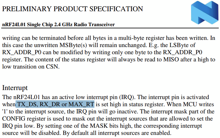
Great! TX_DS (TX Data Sent) and MAX_RT (Max TX retries reached) are the two flags we want to monitor to remedy our issue. It so happens, the IRQ line is setup to respond to these flags by default already! However, MySensors does not listen to the IRQ line during transmission (as shown in Code Snippet 1). So, let’s fix that!
Below you can see the code with our “fix”.
Code Snippet 2
// go, TX starts after ~10us, CE high also enables PA+LNA on supported HW
	RF24_ce(HIGH);
	// timeout counter to detect HW issues
	uint16_t timeout = 0xFFFF;
	do {
		//RF24_status = RF24_getStatus();
		RF24_status = hwDigitalRead(MY_RF24_IRQ_PIN);
	} while  (RF24_status && timeout--);
	//}while  (!(RF24_status & ( _BV(RF24_MAX_RT) | _BV(RF24_TX_DS) )) && timeout--);
	// timeout value after successful TX on 16Mhz AVR ~ 65500, i.e. msg is transmitted after ~36 loop cycles
	RF24_status = RF24_getStatus();
	RF24_ce(LOW);
	// reset interrupts
	RF24_setStatus(_BV(RF24_TX_DS) | _BV(RF24_MAX_RT) );
	// Max retries exceeded
	if(RF24_status & _BV(RF24_MAX_RT)) {
		// flush packet
		RF24_DEBUG(PSTR("!RF24:TXM:MAX_RT\n"));	// max retries, no ACK
		RF24_flushTX();
With the fix shown above, we recaptured transmissions from the same hardware shown in Image 5. Look how nice that data Eye pattern is! (as shown in Image 10 below).
Image 10: Data Eye pattern with transmission IRQ fix
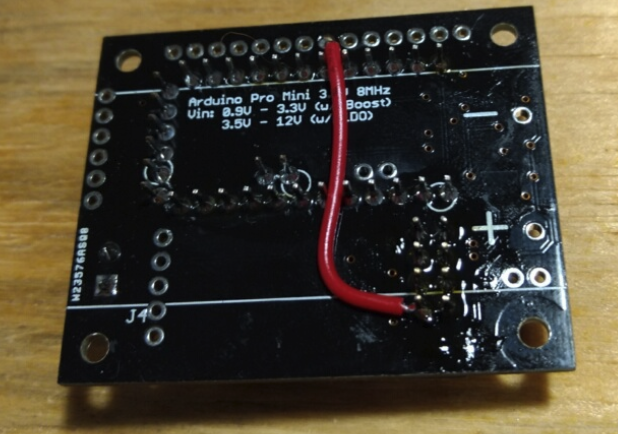
WOW! That is an unbelievable improvement! Thankfully, all those “bad” or “questionable” sensor boards now work like a charm! They all successfully complete presentation and have very low message loss. Sadly, our custom PCB did not pin out the IRQ line so we had to solder a wire from IRQ to an unused pin.
Image 11: Workaround wire
Also, out of the 20ish nRF24L01+ boards all but one are the “clones” with the Shockburst bit inversion. So, this problem may not be as pronounced on genuine or “better clones”. However, it is generally good practice to quiet or mute unnecessary digital communication during transmit/receive if possible.
HALP
We are hardware folk by trade and things like ‘GitHub’ or “software best practices” are not our forte. (For Example, using a bus analyzer to sniff the SPI lines was much easier than digging into the code stack). If somebody was so willing, submitting this fix (or hopefully a better one!) would be great.
@odritter What puzzles me is that the interference in image 6 apparently isn't always present (see image 7), although the behavior of the MySensors stack is always identical (see image 8 and the matching code snippet 1).
Do you see a pattern when it is present and when not?Also, switching to using the nRF24 interrupt line will break MySensors for a lot of (existing) boards, that don't have the IRQ line connected.
So, if we decide to add a silent period to the stack, we also need a non-IRQ implementation based on e.g. a delay.http://yveaux.blogspot.nl
-
@odritter What puzzles me is that the interference in image 6 apparently isn't always present (see image 7), although the behavior of the MySensors stack is always identical (see image 8 and the matching code snippet 1).
Do you see a pattern when it is present and when not?Also, switching to using the nRF24 interrupt line will break MySensors for a lot of (existing) boards, that don't have the IRQ line connected.
So, if we decide to add a silent period to the stack, we also need a non-IRQ implementation based on e.g. a delay.Here is a modified RF24 stack with (among other little changes) a waiting period and no IRQ line (as @Yveaux suggested) for testing: https://github.com/tekka007/MySensors/tree/OptimizedRF24polling
Using the previously mentioned sensor board with a header socket, we observed that almost any nRF24L01+ board worked when cabled (~6 inches) rather than directly plugging into the sensor board. (BUT WHY?????)
Is this setup referring to image 7?
-
Here is a modified RF24 stack with (among other little changes) a waiting period and no IRQ line (as @Yveaux suggested) for testing: https://github.com/tekka007/MySensors/tree/OptimizedRF24polling
Using the previously mentioned sensor board with a header socket, we observed that almost any nRF24L01+ board worked when cabled (~6 inches) rather than directly plugging into the sensor board. (BUT WHY?????)
Is this setup referring to image 7?
@Yveaux To be clear, I realize my code snippet "fix" would break anyone who doesn't already have the IRQ hooked up. This is where we are asking for a contributor more experienced with generalizing to the MySensors library and looking for #defines or such to play nice.
As for what is different between image 6 and image 7 I admit our description in that section gets a little hand wavy for brevity. Image 7 is an auto-ACK from the nRF24L01+ ShockBurst where Image 6 is an outgoing message. You can see evidence of this in image 3 where outgoing messages (like image 6) have a payload (containing MySensors info) and auto-ACKs have no payload (shown as a grey'd out array).
Once I saw that the hardware transmission can be pristine it started me thinking what was so different between a normal message and an auto-ACK. SPI communication.
A word of caution reading too much into early debug steps mentioned (just before image 2). We decided to include these to give background information on what kinds of troubleshooting steps we tried. Some were tried out of sleep deprived desperation and what appeared to "fix" the problem at the time may have only modified the conditions that didn't work. We were not into "rigorous testing mode" at this point in time. We were blindly stabbing in the dark hoping something would work. Additionally, these early debug steps were done without any knowledge of other spectral content in the environment. Once we started using the SDR we observed the spectrum first and moved the nRF channel in a clear and free band to ensure our measurements were only of the nRF boards.
-
Here is a modified RF24 stack with (among other little changes) a waiting period and no IRQ line (as @Yveaux suggested) for testing: https://github.com/tekka007/MySensors/tree/OptimizedRF24polling
Using the previously mentioned sensor board with a header socket, we observed that almost any nRF24L01+ board worked when cabled (~6 inches) rather than directly plugging into the sensor board. (BUT WHY?????)
Is this setup referring to image 7?
@tekka I peaked at the delay you added to the RF24.cpp file. It looks like your calculation is not considering auto-ACK unless I am missing something. I have given some thought to what I think needs to be considered to completely avoid all possible transmissions. See below
optimal delay with ShockBurst = TX state transition delay + (nRF packet length * DataRate + auto-ACK timeout) * (ACKretries + 1)
optimal delay without SB = TX state transition delay + nRF packet length * DataRateThe problem I ran into doing a static delay is that the delay time can get quite large if considering ACK retires making the system very slow. Reducing the amount of polling should help interference even if all SPI communication isn't avoided during every possible transmission. I would definitely prefer the IRQ line used if defined and if not then use a delay (either with or without retires in mind).
-
@Yveaux To be clear, I realize my code snippet "fix" would break anyone who doesn't already have the IRQ hooked up. This is where we are asking for a contributor more experienced with generalizing to the MySensors library and looking for #defines or such to play nice.
As for what is different between image 6 and image 7 I admit our description in that section gets a little hand wavy for brevity. Image 7 is an auto-ACK from the nRF24L01+ ShockBurst where Image 6 is an outgoing message. You can see evidence of this in image 3 where outgoing messages (like image 6) have a payload (containing MySensors info) and auto-ACKs have no payload (shown as a grey'd out array).
Once I saw that the hardware transmission can be pristine it started me thinking what was so different between a normal message and an auto-ACK. SPI communication.
A word of caution reading too much into early debug steps mentioned (just before image 2). We decided to include these to give background information on what kinds of troubleshooting steps we tried. Some were tried out of sleep deprived desperation and what appeared to "fix" the problem at the time may have only modified the conditions that didn't work. We were not into "rigorous testing mode" at this point in time. We were blindly stabbing in the dark hoping something would work. Additionally, these early debug steps were done without any knowledge of other spectral content in the environment. Once we started using the SDR we observed the spectrum first and moved the nRF channel in a clear and free band to ensure our measurements were only of the nRF boards.
@odritter said in nRF24L01+ Communication Failure: Root Cause and “Solution”:
it started me thinking what was so different between a normal message and an auto-ACK. SPI communication.
And the all important fact that the ack message on air comes from the receiving node, instead of the sending one.
My gut feeling tells me you are masking a hardware (design) flaw with software. If it helps in your case, good for you, but I'd like to understand it completely before absorbing it in the stack.http://yveaux.blogspot.nl
-
@tekka I have been testing this (2.3.2b) on a node for the last 9.5 hours and so far no problems.
I will probably flash the GW with this today and see how that goes, not expecting any issues though! ;)
One question though..... Does this 'fix' also apply to when the nrf is in Rx mode as well? If there is no spi activity during Rx then I guess it's a moot point. But I'd be interested in the answer.
-
@odritter said in nRF24L01+ Communication Failure: Root Cause and “Solution”:
it started me thinking what was so different between a normal message and an auto-ACK. SPI communication.
And the all important fact that the ack message on air comes from the receiving node, instead of the sending one.
My gut feeling tells me you are masking a hardware (design) flaw with software. If it helps in your case, good for you, but I'd like to understand it completely before absorbing it in the stack. -
@odritter said in nRF24L01+ Communication Failure: Root Cause and “Solution”:
it started me thinking what was so different between a normal message and an auto-ACK. SPI communication.
And the all important fact that the ack message on air comes from the receiving node, instead of the sending one.
My gut feeling tells me you are masking a hardware (design) flaw with software. If it helps in your case, good for you, but I'd like to understand it completely before absorbing it in the stack.@yveaux I agree this fix may be covering up a problem in our design. As @mfalkvidd mentioned in his post we did put the antenna in an unusual location (not ideal). So it is entirely possible our problems are caused by the antenna placement, nRF clones, or something else entirely. However, we believe we are not alone in the issues we encountered or any design flaw we made.
That being said, constantly polling during TX transmission should be avoided as it is unnecessary. MySensors can calculate how long a transmission should take and hold off for a least the first (or all possible) transmission(s). Implementing a delay should be minimal risk and can only benefit. Implementing the IRQ is more involved to implement properly and higher risk (though I think worth it).
-
@tekka I have been testing this (2.3.2b) on a node for the last 9.5 hours and so far no problems.
I will probably flash the GW with this today and see how that goes, not expecting any issues though! ;)
One question though..... Does this 'fix' also apply to when the nrf is in Rx mode as well? If there is no spi activity during Rx then I guess it's a moot point. But I'd be interested in the answer.
@skywatch This fix only applies to the TX for three reasons.
- Our method for measuring transmission quality can only observe TX (not RX) so we would need a different way to assess RX
- TX timing is well known from start to finish so muting the communication while it is happening is relatively straightforward. RX is a different story
- MySensors already implements IRQ for RX and likely already gains whatever benefit there is to be had limiting communication during RX (though I didn't look into this extensively to confirm)
I am open to ideas on how to assess the RX side if anyone has any suggestions. However for us, implementing the IRQ fix for TX made our boards go from barely working to working like a champ!
-
@odritter Thanks for the clarification! - I learn something new (again)... :)
My question was based on the fact that if enough energy is present in the spi signal to imprint on the Tx output, then it would be even worse for the Rx side as the levels of signal received would be much lower than anything transmitted.
-
@yveaux I agree this fix may be covering up a problem in our design. As @mfalkvidd mentioned in his post we did put the antenna in an unusual location (not ideal). So it is entirely possible our problems are caused by the antenna placement, nRF clones, or something else entirely. However, we believe we are not alone in the issues we encountered or any design flaw we made.
That being said, constantly polling during TX transmission should be avoided as it is unnecessary. MySensors can calculate how long a transmission should take and hold off for a least the first (or all possible) transmission(s). Implementing a delay should be minimal risk and can only benefit. Implementing the IRQ is more involved to implement properly and higher risk (though I think worth it).
@odritter said in nRF24L01+ Communication Failure: Root Cause and “Solution”:
constantly polling during TX transmission should be avoided as it is unnecessary
There is no mention in the nRF24L01+ datasheet of (potential) issues caused by SPI transfers during TX, so where is your statement based on?
-
@odritter said in nRF24L01+ Communication Failure: Root Cause and “Solution”:
it started me thinking what was so different between a normal message and an auto-ACK. SPI communication.
And the all important fact that the ack message on air comes from the receiving node, instead of the sending one.
My gut feeling tells me you are masking a hardware (design) flaw with software. If it helps in your case, good for you, but I'd like to understand it completely before absorbing it in the stack.@yveaux I would be happy to provide our schematic and layout details if you think it would be helpful in identifying the hardware design flaw we made. If there is something we could do to fix this with a board change, that would be interesting to know/consider. (Especially if it ends up being mistake that is commonly made by others using who are also using the nRF24 Board).
Alternatively, it could be an issue with our specific nRF24L01+ boards. While we did order some from Amazon and some from AliExpress, out best guess is that they are all counterfeit/clones. If you know of a source where we could order a board that in confidently authentic, that would be an interesting experiment as well.
-
@yveaux I would be happy to provide our schematic and layout details if you think it would be helpful in identifying the hardware design flaw we made. If there is something we could do to fix this with a board change, that would be interesting to know/consider. (Especially if it ends up being mistake that is commonly made by others using who are also using the nRF24 Board).
Alternatively, it could be an issue with our specific nRF24L01+ boards. While we did order some from Amazon and some from AliExpress, out best guess is that they are all counterfeit/clones. If you know of a source where we could order a board that in confidently authentic, that would be an interesting experiment as well.
@ben036 I would certainly like to have a look at your design files.
You could give Ebyte modules a try : https://forum.mysensors.org/topic/9668/cdebyte-s-new-nrf24-modules-are-great-and-cheap
I have very good experience with these, and are probably using authentic nrf24's -
@ben036 I would certainly like to have a look at your design files.
You could give Ebyte modules a try : https://forum.mysensors.org/topic/9668/cdebyte-s-new-nrf24-modules-are-great-and-cheap
I have very good experience with these, and are probably using authentic nrf24's -
@odritter said in nRF24L01+ Communication Failure: Root Cause and “Solution”:
constantly polling during TX transmission should be avoided as it is unnecessary
There is no mention in the nRF24L01+ datasheet of (potential) issues caused by SPI transfers during TX, so where is your statement based on?
@yveaux My statement is based on the assumption that everything can interfere with your desired signal. It's just a matter of how much. It's very possible that genuine nRF boards are less susceptible to the interference we have shown. However, all the nRF boards we have are suspected clones so I do not have a way to direct compare clone vs genuine (unless we purchase from the Ebyte link you provided).
I have provided a link below to a public application note I came across that provides some background information on sources of interference and how it impacts your desired signal/receiver. Unfortunately it gets very technical at times and assumes a large amount of base RF knowledge so its usefulness may be limited. Nonetheless, I thought I would share if anyone was interested.
Testing and Troubleshooting Digital RF Communications Receiver Designs
The nRF uses a sampled IF receiver as described in section 1.2.2 and similar
to what is shown in figure 4. Section 3.2.2 covers some interfering signals but mostly talks about more complex modulation schemes than the nRF uses.I went back and did an additional experiment using only our Gateway and the Software Defined Radio (SDR) to measure interference on something other than our sensor PCB.
My setup:
Gateway=RaspberryPi 3 with cabled nRF24L01+ hanging out in free space
SDR=USRP B210 with 2.4GHz Vertical antenna
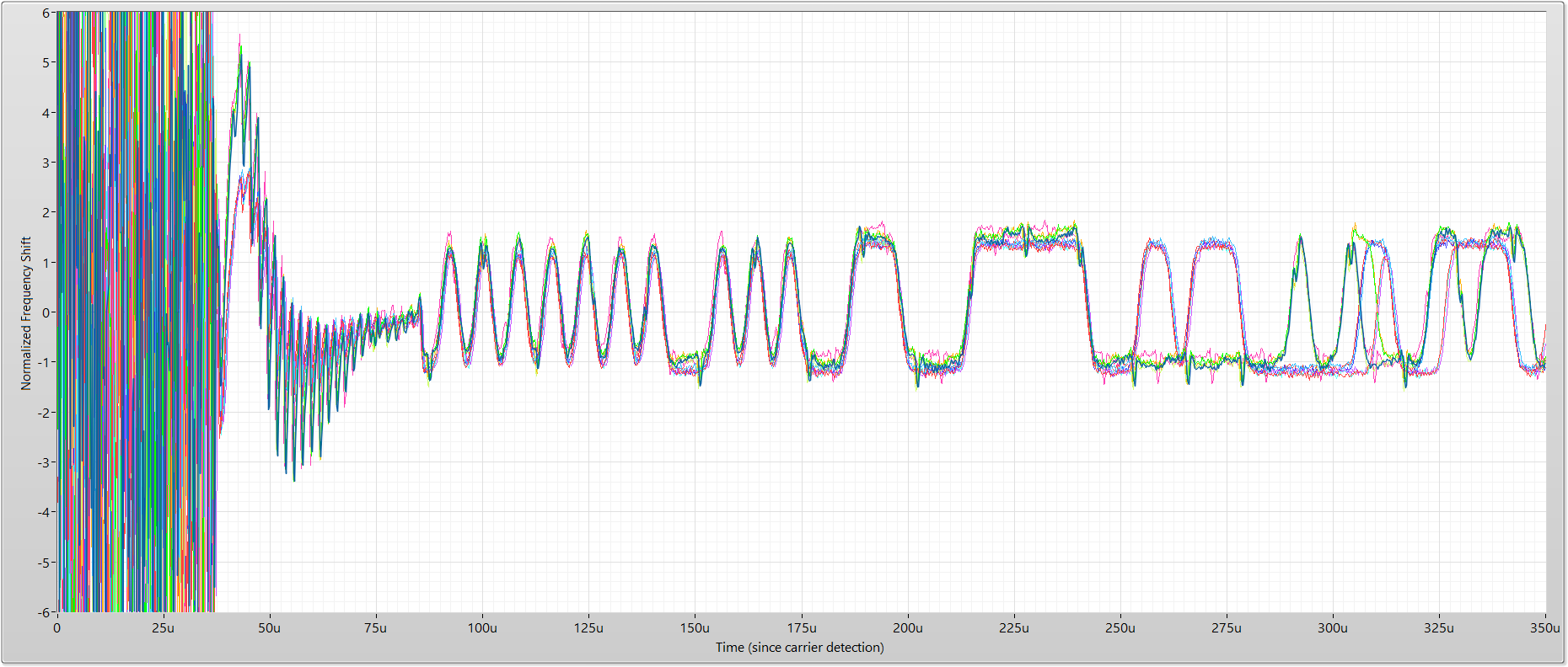
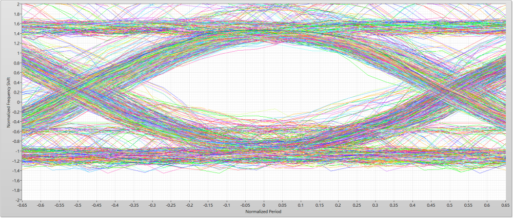
Gateway and SDR placed about 2 feet apart in the middle of a roomGateway transmitted 16 packets for both graphs. The only difference between the two graphs: upper graph constantly polls TX status where the lower graph uses the IRQ line to wait for completion. The physical hardware setup was unchanged between the two measurements.
TX Status Polling
IRQ Wait
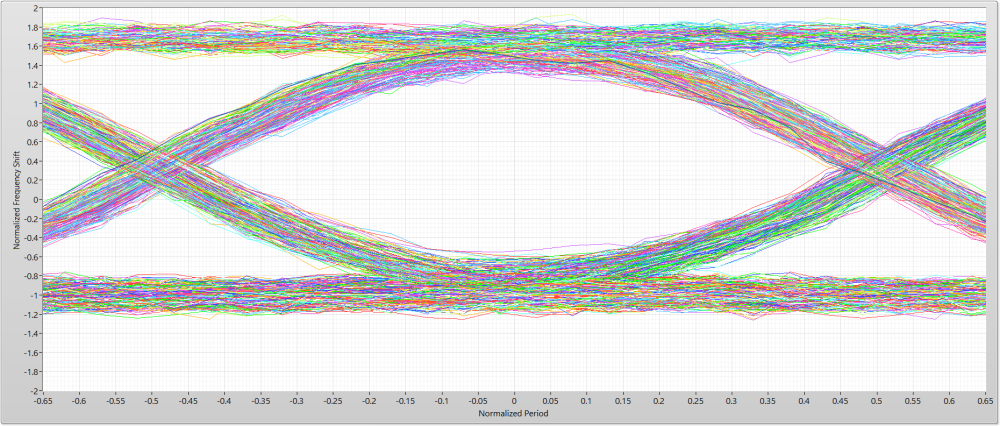
These data Eye patterns were taken with a single nRF board (in contrast, the Eye patterns included in the original post are a composite of 10 different nRF boards)
-
@odritter Thanks for the clarification! - I learn something new (again)... :)
My question was based on the fact that if enough energy is present in the spi signal to imprint on the Tx output, then it would be even worse for the Rx side as the levels of signal received would be much lower than anything transmitted.
@skywatch said in nRF24L01+ Communication Failure: Root Cause and “Solution”:
@odritter Thanks for the clarification! - I learn something new (again)... :)
My question was based on the fact that if enough energy is present in the spi signal to imprint on the Tx output, then it would be even worse for the Rx side as the levels of signal received would be much lower than anything transmitted.
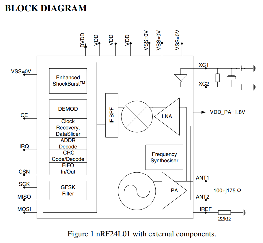
It certainly is possible the Rx side could be even worse. However, it strongly depends on where the interference is coming in. For instance, if the interference happened before the Low Noise Amplifier (LNA) then it would very likely be just as bad or even worse. However, if the interference happened after the LNA it may not have anywhere near as much impact since the signal should be much larger. Though, if the interference impacted the digitization (not really shown in the block diagram explicitly) then it would likely have a significant impact.
Thinking about the TX side of things, the interference is very likely occurring before the modulator (to the left of the PA) since I can "see" the SPI interference with the SDR after it has been demodulated. I have included the nRF block diagram from the datasheet below for reference.
-
@odritter What puzzles me is that the interference in image 6 apparently isn't always present (see image 7), although the behavior of the MySensors stack is always identical (see image 8 and the matching code snippet 1).
Do you see a pattern when it is present and when not?Also, switching to using the nRF24 interrupt line will break MySensors for a lot of (existing) boards, that don't have the IRQ line connected.
So, if we decide to add a silent period to the stack, we also need a non-IRQ implementation based on e.g. a delay.@yveaux said in nRF24L01+ Communication Failure: Root Cause and “Solution”:
@odritter What puzzles me is that the interference in image 6 apparently isn't always present (see image 7), although the behavior of the MySensors stack is always identical (see image 8 and the matching code snippet 1).
Do you see a pattern when it is present and when not?Also, switching to using the nRF24 interrupt line will break MySensors for a lot of (existing) boards, that don't have the IRQ line connected.
So, if we decide to add a silent period to the stack, we also need a non-IRQ implementation based on e.g. a delay.Indeed, the RF Nano has no connected IRQ pins (and uses the NRF24 non-plus version..).
Although it may be unrelated, it's fascinating that this is another instance of MySensors being 'too fast', and 'needing a delay' to work better.