Pir AS 312 with 2 rechargeable AAA battery. Boost needed?
-
@nca78 All clear! What's your experience with this ME2188 booster? My feedback is positive: cheap, low power consumption, at least on the basis my measurement (not so accurate), and no noise that interfere with the radio module and the AS312 PIR.
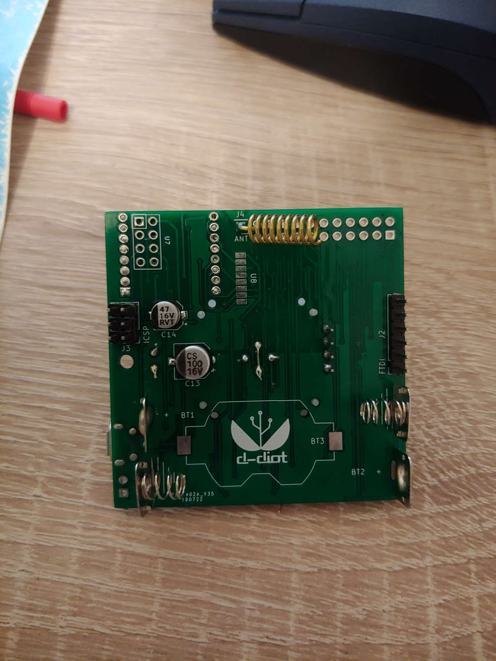
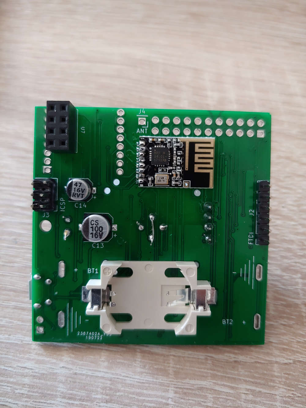
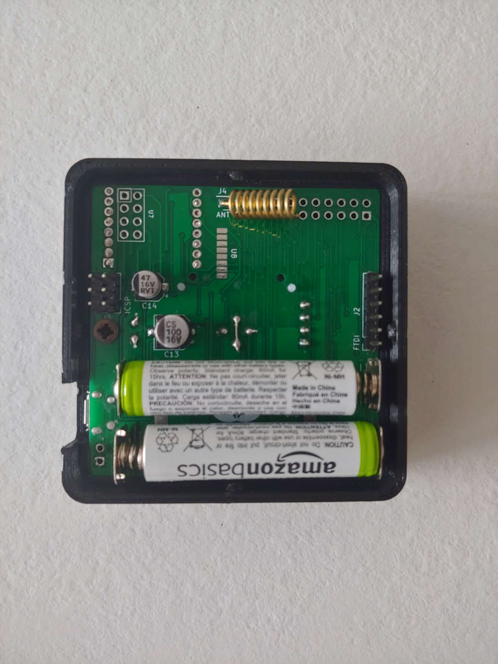
Below the board (v.1.0) with 2xAAA batteries and RFM69 radio module
CR2032 battery and NRF24 radio module (THT)
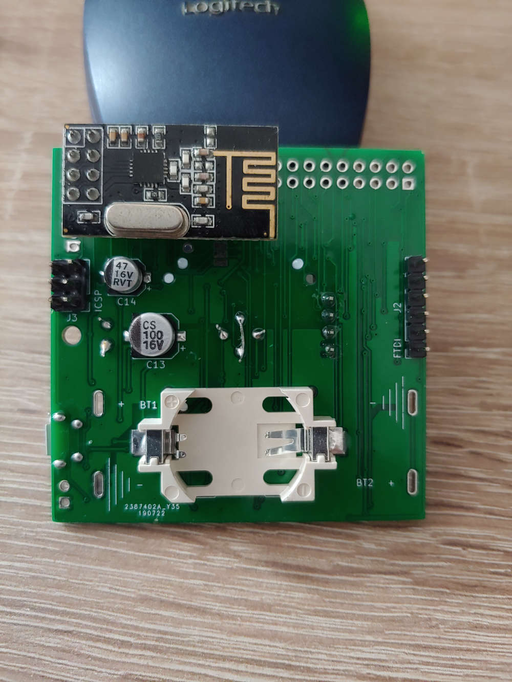
CR2032 battery and NRF24 radio module (SMD)
The board v.2.0 is coming. If someone is interested, here all the project files (Kicad)
@franz-unix said in Pir AS 312 with 2 rechargeable AAA battery. Boost needed?:
My feedback is positive: cheap, low power consumption, at least on the basis my measurement (not so accurate), and no noise that interfere with the radio module and the AS312 PIR.
At least no visible interference with the radio module, but you might get some.
And for RF radiation, interferences and range, no clearance/orientation of the antennas is not good too. -
@franz-unix said in Pir AS 312 with 2 rechargeable AAA battery. Boost needed?:
My feedback is positive: cheap, low power consumption, at least on the basis my measurement (not so accurate), and no noise that interfere with the radio module and the AS312 PIR.
At least no visible interference with the radio module, but you might get some.
And for RF radiation, interferences and range, no clearance/orientation of the antennas is not good too.@scalz with the RFM69 radio module (868 Mhz) I can cover the whole house (about 100 m2), with 3 walls between the gateway and the node, so, for my use case is adequate.
With the NRF24 radio module (THT version) I have the same (poor) range that I can obtain with an Arduino and the same radio module connected with jumper wires, so on the basis of my test the quality of the radio signal is not affected by the boost converter.
I have not yet deeply tested the pcb with the smd version of the NRF24 radio module.
In any case do you have any suggestion for a better orientation/clearance of the antenna? Please note that for the RFM69 radio module you can place the antenna in any direction or side of the PCB that you prefer.
-
@franz-unix
yes, rfm69 modules are great. I prefer them too, and already made custom boards with boosters in the past with these (some with filters or not).But I didn't say your board won't work :)
Just meant:- you would need tools (scope, vna etc) to know about intereferences.
- Same, that's a bad practice to not have any clearance around the antenna.
Like you said, nrf24 has poor range, still you kept a bad orientation ;) You could rotate it 90° so antenna would be outside your board, same for rfm69.
But don't change that for me. I prefer modern mcus, that's a while I've used a 328p mcu!
Like you said if you're happy with results, I'm glad for you too! When it's for personal use, sure, we can take shortcuts, I understand. Craftsman always knows where the little flaws are :)Keep the good work, your board looks nice :+1:
@scalz I know that you are a beast in the board design :grin:
Thank you for sharing your experience! :wink:Newer MCU, like NRF52 will be also my next step, but for the moment I feel more comfortable with the well known and easy to use ATMega328P.
I agree with you, the range and the reliability of the RFM69 is by far better than NRF24.
-
And... the 3d printed case for the board V.1.0
Some adjustment in the tolerances and print settings are required, but the final results may not change so much.
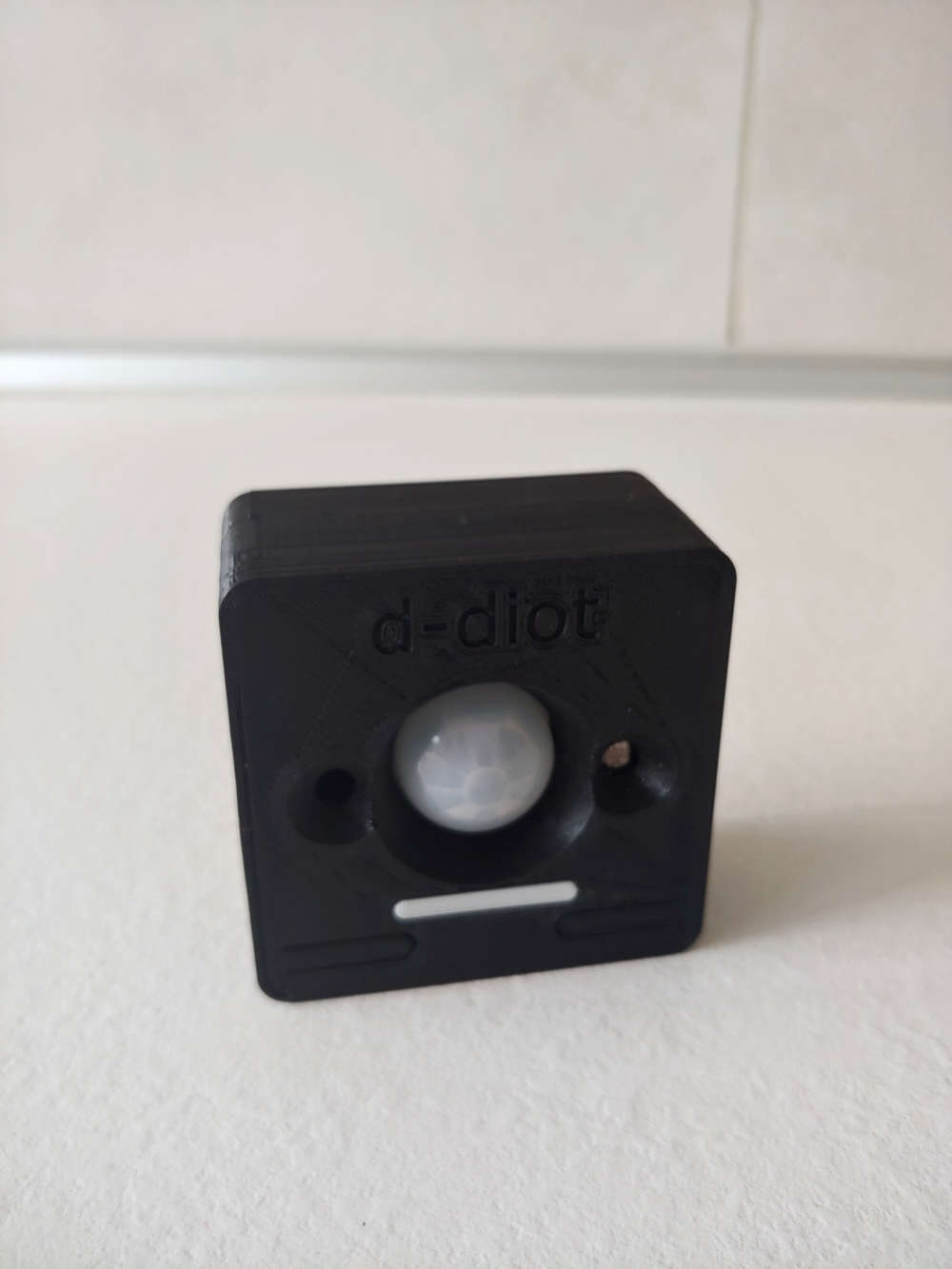
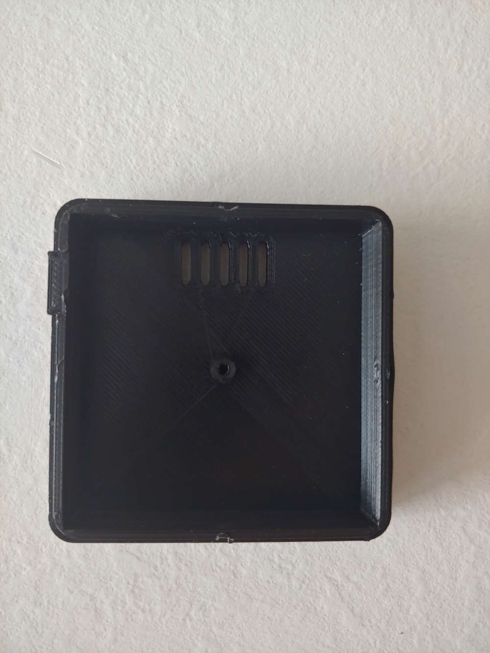
The case for the board V.2.0 will be similar, only the position of the LED will change.
-
If you have room for a AA, an LiFePo4 battery is right in the sweet spot.
I have seen LiFePo4 AAA batteries, but they are really hard to find.@rozpruwacz said in Pir AS 312 with 2 rechargeable AAA battery. Boost needed?:
@franz-unix said in Pir AS 312 with 2 rechargeable AAA battery. Boost needed?:
About the Li-ion battery, it seems to be a general agreement (see this topic for example) about the fact that the best option to power a node is with AA or AAA batteries. In fact one of the advantages is that you don't need to step up or down the voltage to power the radio and the MCU.
There is no one "best option". The power supply heavily depends on the project requirements. The PIR sensor requires noiseless voltage between 2.7 and 3.3v. This makes use of 2xAA problematic. In my opinion for such a project higher voltage supply with low quiescent current ldo is the best option. And it happens that li-ion battery with its voltage range and 3v ldo makes them perfect match. At least this is how I did it in my homE I went even further in my project and there is two ldos, one for pir and one for mcu + rf module as those two components creates large spikes in current flow as they work making supply voltage noisy.
PS. The other benefit of rechargable batteries is that they are rechargable :) so you don't need to remember to buy batteries when you go out of them.
you will handle the pir in your software but generally the pir needs to be powered all the time so no need for shutdown mode in your boost converter. The other thing is that pir doesn't linke noisy power supply, and dc converters are rather noisy especially in low current area. I would recommend t
-
@rozpruwacz said in Pir AS 312 with 2 rechargeable AAA battery. Boost needed?:
@franz-unix said in Pir AS 312 with 2 rechargeable AAA battery. Boost needed?:
About the Li-ion battery, it seems to be a general agreement (see this topic for example) about the fact that the best option to power a node is with AA or AAA batteries. In fact one of the advantages is that you don't need to step up or down the voltage to power the radio and the MCU.
There is no one "best option". The power supply heavily depends on the project requirements. The PIR sensor requires noiseless voltage between 2.7 and 3.3v. This makes use of 2xAA problematic. In my opinion for such a project higher voltage supply with low quiescent current ldo is the best option. And it happens that li-ion battery with its voltage range and 3v ldo makes them perfect match. At least this is how I did it in my homE I went even further in my project and there is two ldos, one for pir and one for mcu + rf module as those two components creates large spikes in current flow as they work making supply voltage noisy.
PS. The other benefit of rechargable batteries is that they are rechargable :) so you don't need to remember to buy batteries when you go out of them.
you will handle the pir in your software but generally the pir needs to be powered all the time so no need for shutdown mode in your boost converter. The other thing is that pir doesn't linke noisy power supply, and dc converters are rather noisy especially in low current area. I would recommend t
@seniora the board supports multiple batteries and multiple radio modules.
When Vcc goes below 2.7V (BoostThreshold in the sketch) the booster is turned on and stay always on, while when Vcc is > 2.7 the booster is turned off and stay off. This is the case of a fully charged CR2032 battery or 2xAAA disposable (Alkaline) batteries.
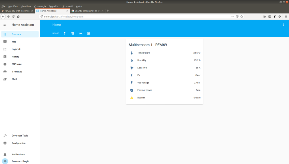
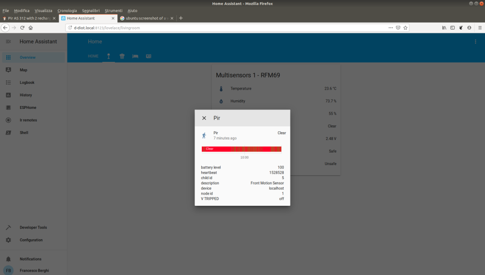
With 2xAAA rechargeable batteries (NiMH) Vcc is max 2.4V so the booster is turned on by the MCU.The ME2188 works well with RFM69 and 2xAAA rechargeable batteries (Vcc < 2.7V): no false positive in the PIR and good range for the radio transmission. See below that in the night with no motion the pir stay off (clear) even if the booster is active.
With the NRF24 radio module and a CR2032 battery I have some (not so frequent) false positive in the PIR, but the booster here is always off (VCC > 2.7V), so this may be caused by something else. Searching around, found this.
Probably is the 2.4 Ghz RF signal of the radio module that triggers some false positive in the PIR!
In fact I observe this false positive when the node wakes up by a timer interrupt and start sending data. -
When you sleep the node with a PIR connected, a small 'nap' before the main sleep helps to settle the Vbat, and it usually avoid false triggering. Maybe this will help:
sleep(500);
sleep(INTERRUPT,RISING, SLEEP_TIME);
Home Assistant / Vera Plus UI7
ESP8266 GW + mySensors 2.3.2
Alexa / Google Home -
When you sleep the node with a PIR connected, a small 'nap' before the main sleep helps to settle the Vbat, and it usually avoid false triggering. Maybe this will help:
sleep(500); sleep(INTERRUPT,RISING, SLEEP_TIME);@rvendrame Thanks, I have tried your small "nap" trick and in fact something is happened... but in the opposite direction! The number of false positive is increased :joy:
But probably this is the way to solve the issue. Please note that, in order to stabilize the battery voltage, in the sketch I already have a cr2032_wait() function that sleep the MCU after each radio transmission, if the battery type is set to CR2032.
-
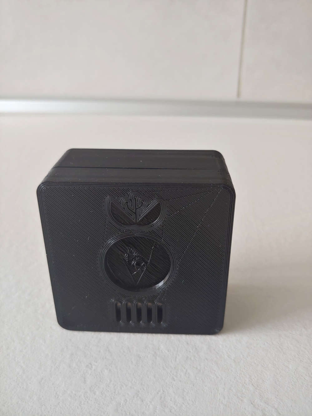
Hi guys, project finished! Now the led are under the Fresnel lens, so the design of the case is more clean (WAF +10 :sunglasses: ).
The final result:
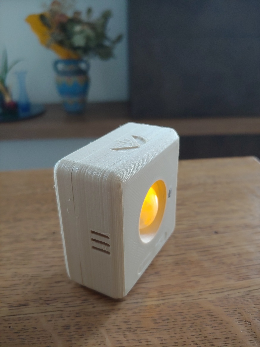
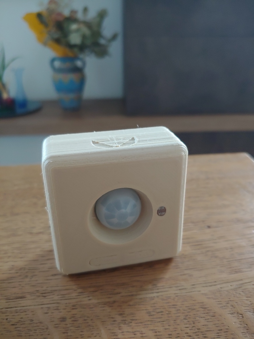

With 2 x AAA batteries and the RFM69 radio module the node works very well and the total cost of the parts is about 10€.
If someone is interested, here a detailed build guide, with the links to all the parts of the project (3d model of the case, Kicad project, gerber files, BOM, firmware).
-
few month ago ,i use tlv61220 step-up boost only for as312 is only 4ua, atmega328p ,battery cr2477 , then get 21ua ,
but now ,i give up boost , i test use ER14335 3.6v CR16340LIPO 【4.2V with diode 0.7V Step-down then 3.5V+- 】 ,same as312 get 18ua,:relaxed: ,ER14335 cost much but 1600mah ! cr16340 750mah rechargeable best choose for me,,,, -
Hi guys, project finished! Now the led are under the Fresnel lens, so the design of the case is more clean (WAF +10 :sunglasses: ).
The final result:
With 2 x AAA batteries and the RFM69 radio module the node works very well and the total cost of the parts is about 10€.
If someone is interested, here a detailed build guide, with the links to all the parts of the project (3d model of the case, Kicad project, gerber files, BOM, firmware).
-
@franz-unix
This is wonderful work... thanks for inspiring me :-)
I know that this is an old thread,
but can you give me a link of the AAA battery holder please ?I just make a node sensor and I want to use it.
Thanks a lot
Denis@DenisJ : Glad to know that this work has been useful for you in some way. :+1:
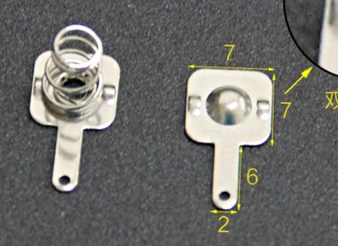
Regarding the AAA battery holder, the footprints on the PCB are for a Keystone 5204 (negative) and Keystone 5226 (positive) contacts.
I have purchased them on ebay; unfortunately the item that I have purchased is not more available, but this one appears to me like the same thing.
-
@DenisJ the link is broken, so I have not seen the contacts that you have bought, but if they are just a little bit smaller and they can fit the hole on the pcb, they should be OK.
-
@franz-unix Hi, this post is very old I hope I can get an answer :)
I have ME2188 here but the behaviour of CE pin in extrange.
If I apply high to CE pin I get my correct 5v but if I change CE pin to low I get 4v on the output and I hope to get 0v.Anyone can share your experience?
-
@franz-unix Hi, this post is very old I hope I can get an answer :)
I have ME2188 here but the behaviour of CE pin in extrange.
If I apply high to CE pin I get my correct 5v but if I change CE pin to low I get 4v on the output and I hope to get 0v.Anyone can share your experience?
@Diego-Serrano said in Pir AS 312 with 2 rechargeable AAA battery. Boost needed?:
@franz-unix Hi, this post is very old I hope I can get an answer :)
I have ME2188 here but the behaviour of CE pin in extrange.
If I apply high to CE pin I get my correct 5v but if I change CE pin to low I get 4v on the output and I hope to get 0v.Hello, this is the normal behavior for this chip. CE will enable the step up, but with CE low it acts as a bridge so you get input voltage at output.
Pretty annoying :)Anyone can share your experience?
My experience was to add an MT9700 power switch before the voltage input of the ME2188. The EN pin of the power switch is connected to the same signal than the CE pin of the MT2188, driven by the microcontroller.
It works fine like this driving a Plantower PM sensor not a PIR (don't pay too much attention at the caps at output I just wanted to have different footprints available).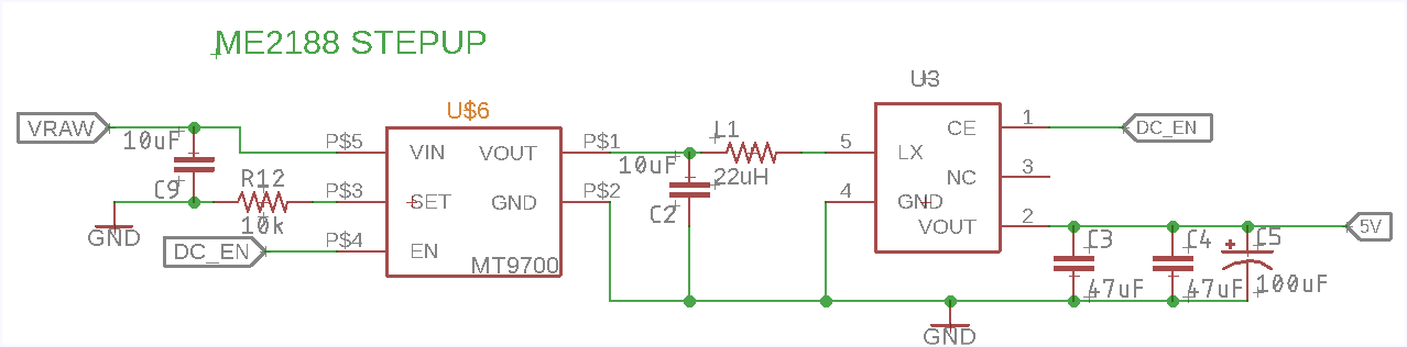
-
@Diego-Serrano said in Pir AS 312 with 2 rechargeable AAA battery. Boost needed?:
@franz-unix Hi, this post is very old I hope I can get an answer :)
I have ME2188 here but the behaviour of CE pin in extrange.
If I apply high to CE pin I get my correct 5v but if I change CE pin to low I get 4v on the output and I hope to get 0v.Hello, this is the normal behavior for this chip. CE will enable the step up, but with CE low it acts as a bridge so you get input voltage at output.
Pretty annoying :)Anyone can share your experience?
My experience was to add an MT9700 power switch before the voltage input of the ME2188. The EN pin of the power switch is connected to the same signal than the CE pin of the MT2188, driven by the microcontroller.
It works fine like this driving a Plantower PM sensor not a PIR (don't pay too much attention at the caps at output I just wanted to have different footprints available).@Nca78 said in Pir AS 312 with 2 rechargeable AAA battery. Boost needed?:
Pretty annoying
Thanks you very much.
-
@nagelc The LiFePo4 batteries will be perfect (AA and AAA), but I arrived at your same conclusion: a little bit to exotic respect to standard alkaline or NiMH batteries.
@rozpruwacz Nice board, is similar to what I want, but unfortunately not exactly the same. I prefer to have one single board to simplify the build and external case design (3d-printable).
Thanks to your suggestion, I have modified a little bit the circuit:
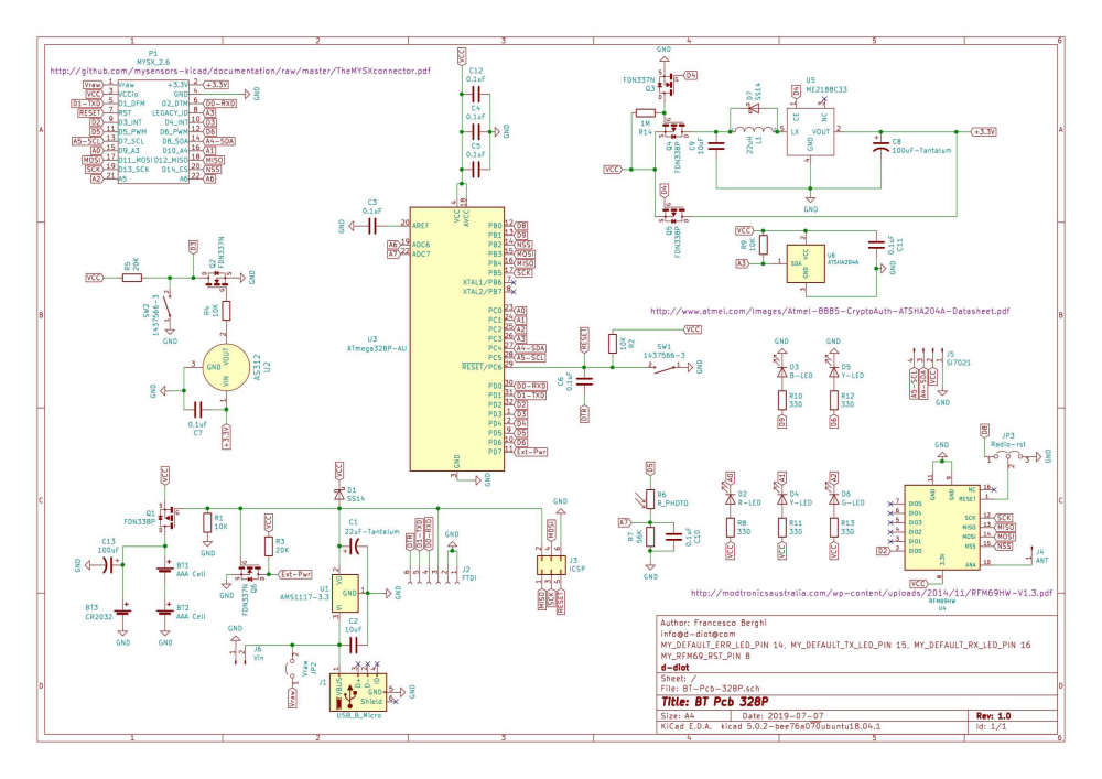
Some consideration and board features:
-
Added footprint for CR2032 coin cell and dedicated 100 uF capacitor to prevent problem related to the low discharge rate of the battery.
-
Added a flyback diode across the inductor to discharge voltage spikes when the circuit is disconnected (mosfet Q3 - Pin D4). Not sure if it is strictly necessary... but just in case!
-
Multiple power options: 2xAAA batteries, 1xCR2032, micro USB (phone charger), J6 pin header. When powered from an external source through USB port or J6, the voltage can be between 4 and 12V. When you power the board through FTDI or ICSP make sure that the voltage is 3.3V, otherwise the radio module will be damaged!
-
Mosfet Q1 offers a reverse polarity protection to the board if the batteries are inserted in the wrong way. It cut off also the batteries compartment when an external power source is present, so you don't have to remove the batteries while powering the board via FTDI, ICSP, USB or J6
-
When VCC is below 2.7V (AAA rechargeable batteries) the boost circuit is activated by the MCU (Pin D4). When VCC is above 2.7V (disposable AAA batteries or CR2032) the circuit is disabled and the PIR is powered directly form VCC (see Q3-Q4-Q5)
-
To increase the battery life, the photoresistor is powered through PIN D5, only when the node is awake. During sleep D5 will be set to LOW, so no current waste.
-
Two momentary switch: 1 for MCU reset and 1 to force the node to wake up
-
Motion led (D3) and low battery / external powerl ed (D5) configurable in the firmware, plus radio activity LEDs
-
Header for Si7021 breakout
-
AS312 Pir with mounting holes for a standard fresnel lens like the one present in the HC-SR501
-
MYSX 2.6 connector to add other sensors.
-
ATSHA204A for security signing
-
Size: 57x57 mm (not so small but also not so big)
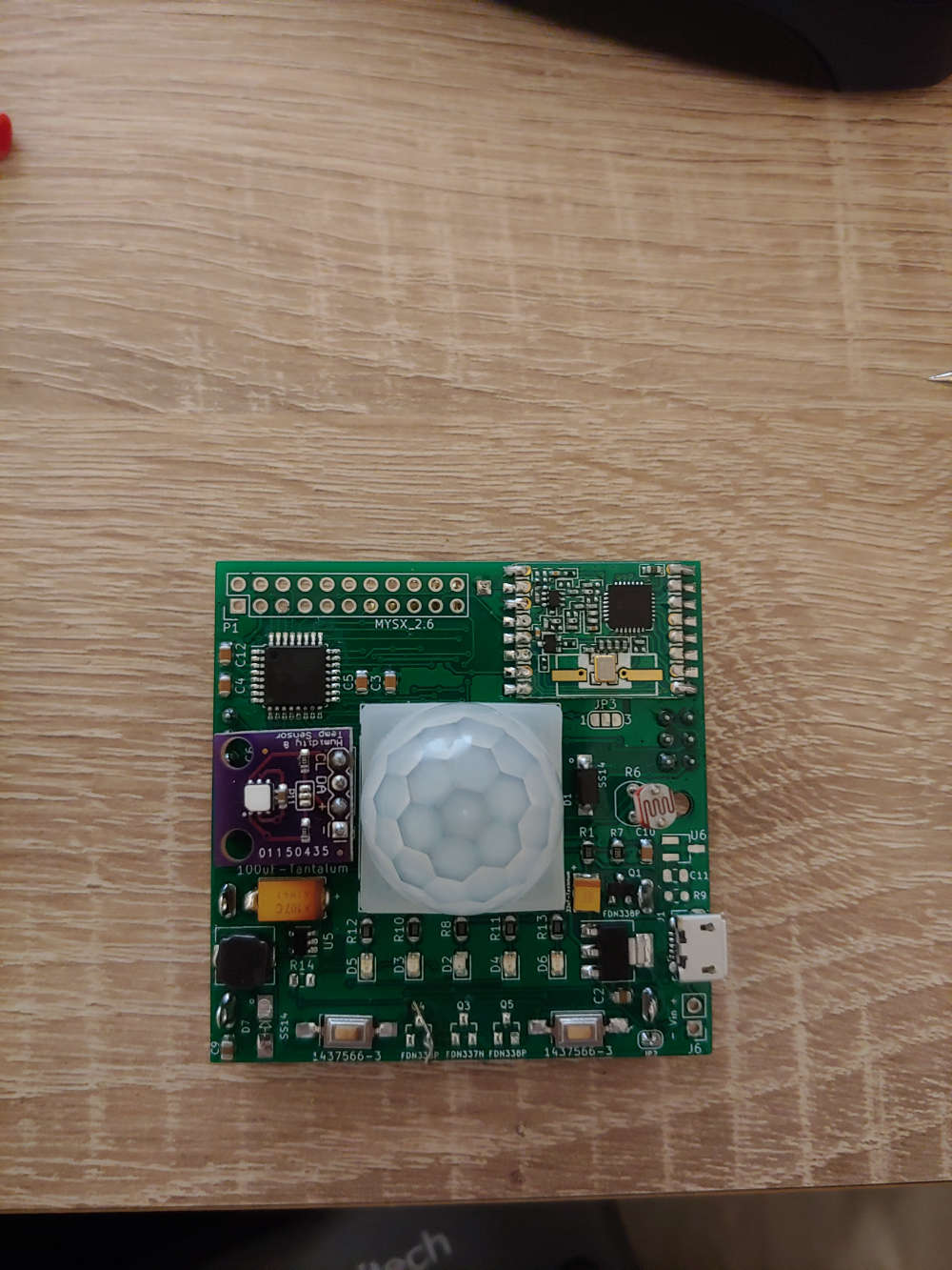
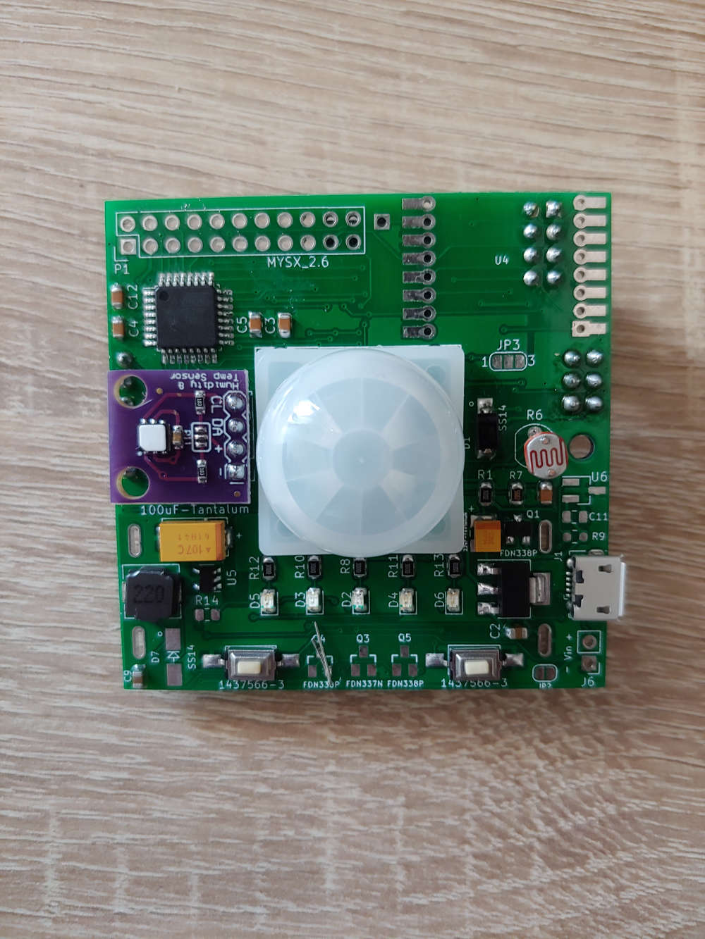
This is how the board looks like
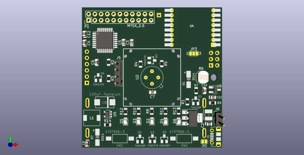
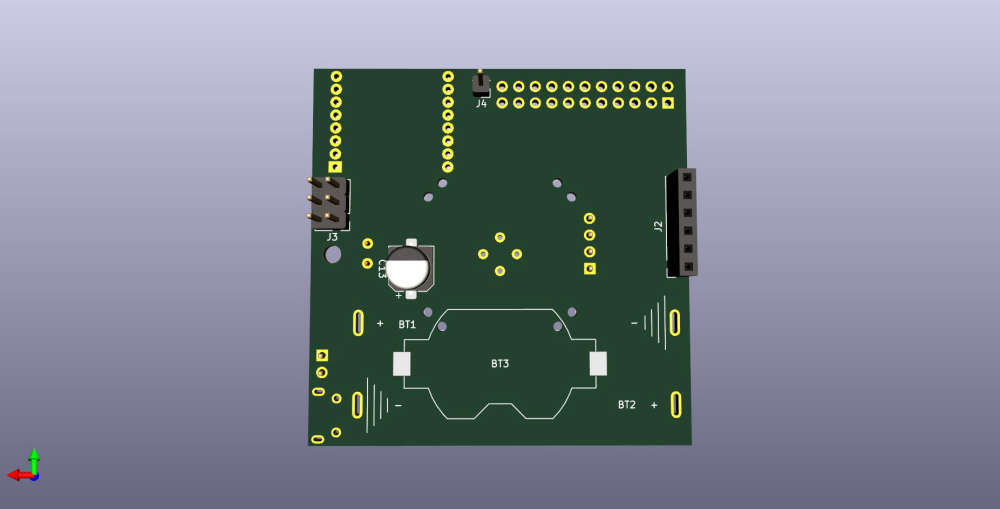
It is still under development, but if someone is interested, the Kicad project is available on github.
... Well the next step is to test the ME2188 boost converter... I hope that it can do its job without triggering false positive on the PIR sensors!
-