Something's cooking in the MySensors labs...
-
Sensbender, Janus, and HALO - they all support multiple RF modules, but the MySensors framework doesn't...until now :)
Example of a dualRF Sensebender serial gateway configuration - as simple as that:
#define MY_GATEWAY_SERIAL

#define MY_RADIO_RF24
#define MY_RADIO_RFM69
#define MY_RFM69_NEW_DRIVER // required for multitransport

// optional (but recommended)
#define MY_RF24_USE_INTERRUPTS
Some of the new features:
- multiple transports with RX queue
- GW does radio-specific routing, however, the network is still limited to 254 nodes
- RFM95 radio driver can run in RFM69 compatibility mode
This is still WIP (and will be for a while) but you can already get your hands dirty and test the PR.
Kudos to @scalz (Janus and HALO) and @tbowmo (Sensebender) for their cool boards!
Have fun!
-
Great work!
Does it include RS485 transport, or only RF for now? Or I've missed that it already works with RF and RS485 simultaneously? -
Nice work @tekka
I'm especially impressed that you have managed to add this support while keeping sketch size for nodes that don't use this feature as small (or even smaller) than before.This is the result from compiling the gatewaySerial sketch for Arduino Pro Mini on my system:
development tekka branch relative size Standard sketch 13276 13262 99,89% Without debug 10504 10488 99,85% Without nrf24 8100 8100 100,00% A serial gateway with nrf24, rfm69, rfm95 and rs485 compiles with the following result (note that it might be hard to fit all transports to the available pins though):
Sketch uses 19946 bytes (64%) of program storage space. Maximum is 30720 bytes. Global variables use 1527 bytes (74%) of dynamic memory, leaving 521 bytes for local variables. Maximum is 2048 bytes. -
Well this is just brilliant! And the timing couldn't be any better, as I was just about to conquer our garden with an army of RFM69 nodes. :D
For the last three days I was sending an incrementing number every five minutes with each an NRF24 and RFM69 node to a 3.3V Pro Mini MQTT gateway (W5500) without issues. Today I decided to flick the switch and route my existing NRF24 network through it, effectively replacing my trusty ESP MQTT gateway (which I will keep as a backup, just in case) and it's looking good.
RAM:   [=======   ]  74.7% (used 1530 bytes from 2048 bytes)
Flash: [========  ]  84.5% (used 25972 bytes from 30720 bytes)
Here's my basic sketch in case anyone might find it useful:
#include <Arduino.h> #define MY_BAUD_RATE 9600 #define MY_DEBUG #define SKETCH_NAME "Multi-TP Gateway" #define SKETCH_VERSION "1.1" // Ethernet & MQTT config #define MY_GATEWAY_MQTT_CLIENT #define MY_MQTT_CLIENT_ID "mys-gw" #define MY_MQTT_PUBLISH_TOPIC_PREFIX "mys-out" #define MY_MQTT_SUBSCRIBE_TOPIC_PREFIX "mys-in" #define MY_MQTT_USER "username" #define MY_MQTT_PASSWORD "password" #define MY_IP_ADDRESS 192, 168, 178, 215 #define MY_CONTROLLER_IP_ADDRESS 192, 168, 178, 220 #define MY_PORT 1883 // SoftSPI for radios #define MY_SOFTSPI #define MY_SOFT_SPI_SCK_PIN 14 // A0 #define MY_SOFT_SPI_MOSI_PIN 15 // A1 #define MY_SOFT_SPI_MISO_PIN 16 // A2 // NRF config #define MY_RADIO_RF24 #define MY_RF24_CHANNEL 83 #define MY_RF24_PA_LEVEL RF24_PA_HIGH #define MY_RF24_USE_INTERRUPTS #define MY_RF24_IRQ_PIN 3 #define MY_RF24_CE_PIN 7 #define MY_RF24_CS_PIN 8 // RFM config #define MY_RADIO_RFM69 #define MY_RFM69_NEW_DRIVER #define MY_RFM69_NETWORKID 69 #define MY_RFM69_FREQUENCY RFM69_868MHZ #define MY_IS_RFM69HW #define MY_RFM69_IRQ_PIN 2 #define MY_RFM69_CS_PIN 9 // https://github.com/Wiznet/WIZ_Ethernet_Library #include <Ethernet.h> #include <MySensors.h> void presentation() { sendSketchInfo(SKETCH_NAME, SKETCH_VERSION); } void setup() { } void loop() { } -
Sure, will do! I'll get back to you, once I've tested it. Might take a week though.
-
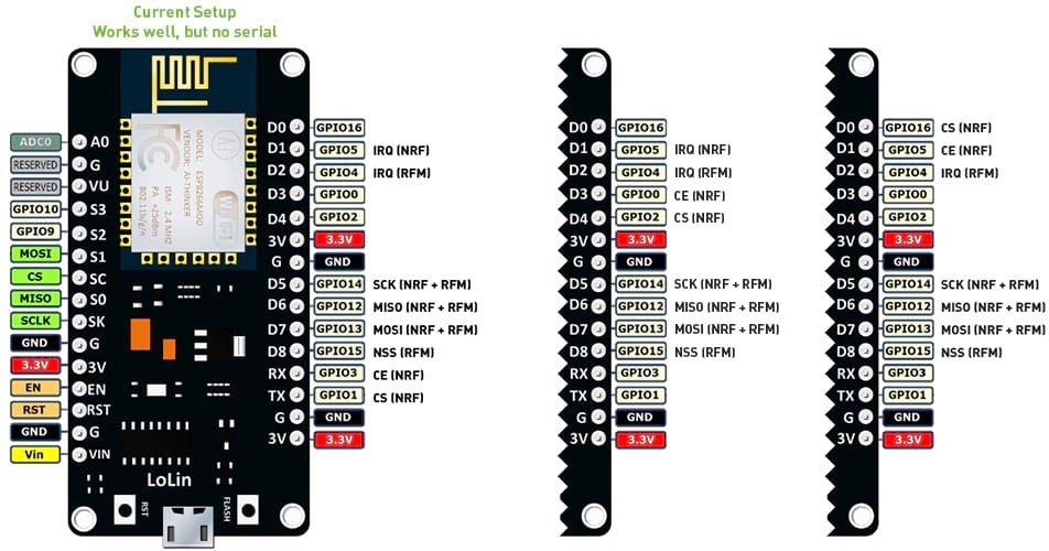
Alright, I got the ESP MQTT GW working for the better part of the last two days, handling an average total of 48 messages (36 sending, 12 requesting) per minute from two nodes and all seems good so far. As you can see in the image below, I'm using the RX (GPIO 3) / TX (GPIO 1) pins for CE and CS and I have
MY_DISABLED_SERIALdefined, which means that I can't see the serial output of the GW. But looking at the corresponding MQTT topics and the serial output of the nodes, I confirmed that every in- and outgoing message was handled correctly.I've tried a bunch of other pin assignments, of which I've included two in the image. With the one shown in the middle, I saw tons of NACKs on the serial output of the NRF24 node. I think this is because D3 (GPIO 0) and D4 (GPIO 2) are used to determine the boot mode of the ESP and are pulled high to VCC. Using them for the IRQ pins isn't going to work either - at least not without external circuitry - because the RFM69 will pull the line down and the NRF24 will pull it up, preventing the ESP from booting / flashing.
If D3 and D4 can't be used, there are only seven easily accessible GPIOs left (not counting RX/TX here) for a total of eight IO pins on both radios (2x IRQ, 3 for SPI, CE, CS and NSS). I decided to leave the IRQ pin of the NRF24 radio unconnected and ended up with a pin assignment as shown on the right. In this setup, all messages received an acknowledgement, even though not all sent messages appeared in the GW serial output, nor in the corresponding MQTT topic.
So yes the dualRF GW is working on a NodeMCU (ESP-12E), if you can do without serial output, don't care about traffic indicator LEDs, inclusion mode and such. Since many of the pins have two, three or more functions depending on the ESPs state, I don't think I would recommend it as a dualRF gateway, unless someone who has more patience steps in to figure out if and how all GPIOs can be made accessible. Better use a different MCU for this.
Let me know if you need a specific log or want me to test something with it. I'd be happy to help. Otherwise I'd like to free my breadboards up for other projects.
GW sketch:
#include <Arduino.h> // #define MY_DEBUG #define MY_DISABLED_SERIAL #define MY_BAUD_RATE 115200 #define SKETCH_NAME "ESP dualRF Gateway" #define SKETCH_VERSION "1.0" // WiFI config #define MY_GATEWAY_ESP8266 #define MY_HOSTNAME "MySensors-ESP-GW" #define MY_WIFI_SSID "ssid" #define MY_WIFI_PASSWORD "pwd" // MQTT config #define MY_GATEWAY_MQTT_CLIENT #define MY_MQTT_CLIENT_ID "my-gw" #define MY_MQTT_PUBLISH_TOPIC_PREFIX "mytest-out" #define MY_MQTT_SUBSCRIBE_TOPIC_PREFIX "mytest-in" #define MY_MQTT_USER "user" #define MY_MQTT_PASSWORD "pwd" #define MY_CONTROLLER_IP_ADDRESS 192, 168, 178, 220 #define MY_PORT 1883 // NRF config #define MY_RADIO_RF24 #define MY_RF24_CHANNEL 83 #define MY_RF24_PA_LEVEL RF24_PA_HIGH #define MY_RF24_USE_INTERRUPTS #define MY_RF24_IRQ_PIN D1 #define MY_RF24_CE_PIN D9 #define MY_RF24_CS_PIN D10 // RFM config #define MY_RADIO_RFM69 #define MY_RFM69_NEW_DRIVER #define MY_RFM69_NETWORKID 69 #define MY_RFM69_FREQUENCY RFM69_868MHZ #define MY_IS_RFM69HW #define MY_RFM69_IRQ_PIN D2 #define MY_RFM69_IRQ_NUM MY_RFM69_IRQ_PIN #define MY_RFM69_CS_PIN D8 #include <ESP8266WiFi.h> #include <ArduinoOTA.h> #include <MySensors.h> void presentation() { sendSketchInfo(SKETCH_NAME, SKETCH_VERSION); } void setup() { ArduinoOTA.onStart([]() { Serial.println("ArduinoOTA start"); }); ArduinoOTA.onEnd([]() { Serial.println("\nArduinoOTA end"); }); ArduinoOTA.onProgress([](unsigned int progress, unsigned int total) { Serial.printf("OTA Progress: %u%%\r", (progress / (total / 100))); }); ArduinoOTA.onError([](ota_error_t error) { Serial.printf("Error[%u]: ", error); if (error == OTA_AUTH_ERROR) { Serial.println("Auth Failed"); } else if (error == OTA_BEGIN_ERROR) { Serial.println("Begin Failed"); } else if (error == OTA_CONNECT_ERROR) { Serial.println("Connect Failed"); } else if (error == OTA_RECEIVE_ERROR) { Serial.println("Receive Failed"); } else if (error == OTA_END_ERROR) { Serial.println("End Failed"); } }); ArduinoOTA.begin(); } void loop() { ArduinoOTA.handle(); } -
Alright, I got the ESP MQTT GW working for the better part of the last two days, handling an average total of 48 messages (36 sending, 12 requesting) per minute from two nodes and all seems good so far. As you can see in the image below, I'm using the RX (GPIO 3) / TX (GPIO 1) pins for CE and CS and I have
MY_DISABLED_SERIALdefined, which means that I can't see the serial output of the GW. But looking at the corresponding MQTT topics and the serial output of the nodes, I confirmed that every in- and outgoing message was handled correctly.I've tried a bunch of other pin assignments, of which I've included two in the image. With the one shown in the middle, I saw tons of NACKs on the serial output of the NRF24 node. I think this is because D3 (GPIO 0) and D4 (GPIO 2) are used to determine the boot mode of the ESP and are pulled high to VCC. Using them for the IRQ pins isn't going to work either - at least not without external circuitry - because the RFM69 will pull the line down and the NRF24 will pull it up, preventing the ESP from booting / flashing.
If D3 and D4 can't be used, there are only seven easily accessible GPIOs left (not counting RX/TX here) for a total of eight IO pins on both radios (2x IRQ, 3 for SPI, CE, CS and NSS). I decided to leave the IRQ pin of the NRF24 radio unconnected and ended up with a pin assignment as shown on the right. In this setup, all messages received an acknowledgement, even though not all sent messages appeared in the GW serial output, nor in the corresponding MQTT topic.
So yes the dualRF GW is working on a NodeMCU (ESP-12E), if you can do without serial output, don't care about traffic indicator LEDs, inclusion mode and such. Since many of the pins have two, three or more functions depending on the ESPs state, I don't think I would recommend it as a dualRF gateway, unless someone who has more patience steps in to figure out if and how all GPIOs can be made accessible. Better use a different MCU for this.
Let me know if you need a specific log or want me to test something with it. I'd be happy to help. Otherwise I'd like to free my breadboards up for other projects.
GW sketch:
#include <Arduino.h> // #define MY_DEBUG #define MY_DISABLED_SERIAL #define MY_BAUD_RATE 115200 #define SKETCH_NAME "ESP dualRF Gateway" #define SKETCH_VERSION "1.0" // WiFI config #define MY_GATEWAY_ESP8266 #define MY_HOSTNAME "MySensors-ESP-GW" #define MY_WIFI_SSID "ssid" #define MY_WIFI_PASSWORD "pwd" // MQTT config #define MY_GATEWAY_MQTT_CLIENT #define MY_MQTT_CLIENT_ID "my-gw" #define MY_MQTT_PUBLISH_TOPIC_PREFIX "mytest-out" #define MY_MQTT_SUBSCRIBE_TOPIC_PREFIX "mytest-in" #define MY_MQTT_USER "user" #define MY_MQTT_PASSWORD "pwd" #define MY_CONTROLLER_IP_ADDRESS 192, 168, 178, 220 #define MY_PORT 1883 // NRF config #define MY_RADIO_RF24 #define MY_RF24_CHANNEL 83 #define MY_RF24_PA_LEVEL RF24_PA_HIGH #define MY_RF24_USE_INTERRUPTS #define MY_RF24_IRQ_PIN D1 #define MY_RF24_CE_PIN D9 #define MY_RF24_CS_PIN D10 // RFM config #define MY_RADIO_RFM69 #define MY_RFM69_NEW_DRIVER #define MY_RFM69_NETWORKID 69 #define MY_RFM69_FREQUENCY RFM69_868MHZ #define MY_IS_RFM69HW #define MY_RFM69_IRQ_PIN D2 #define MY_RFM69_IRQ_NUM MY_RFM69_IRQ_PIN #define MY_RFM69_CS_PIN D8 #include <ESP8266WiFi.h> #include <ArduinoOTA.h> #include <MySensors.h> void presentation() { sendSketchInfo(SKETCH_NAME, SKETCH_VERSION); } void setup() { ArduinoOTA.onStart([]() { Serial.println("ArduinoOTA start"); }); ArduinoOTA.onEnd([]() { Serial.println("\nArduinoOTA end"); }); ArduinoOTA.onProgress([](unsigned int progress, unsigned int total) { Serial.printf("OTA Progress: %u%%\r", (progress / (total / 100))); }); ArduinoOTA.onError([](ota_error_t error) { Serial.printf("Error[%u]: ", error); if (error == OTA_AUTH_ERROR) { Serial.println("Auth Failed"); } else if (error == OTA_BEGIN_ERROR) { Serial.println("Begin Failed"); } else if (error == OTA_CONNECT_ERROR) { Serial.println("Connect Failed"); } else if (error == OTA_RECEIVE_ERROR) { Serial.println("Receive Failed"); } else if (error == OTA_END_ERROR) { Serial.println("End Failed"); } }); ArduinoOTA.begin(); } void loop() { ArduinoOTA.handle(); }Nice work @BearWithBeard !
Luckily, someone has already figured out the ins and outs of the different pins. His name is Neil Kolban. I bought his book on esp8266 and it was very useful to me when figuring out the limitations of each pin.
I have not used the esp32 much, but I am pretty sure Neil’s book on it is great. https://leanpub.com/kolban-ESP32
-
Great job!
-
Hi, I have a question about signing/encryption.
I have rs485 nodes without these features (as they are not really useful here), but I want to add nrf nodes, where I would like to implement these to have a secure network.
So can I use rs485 nodes without signing/encryption and nrf nodes with them enabled at the same time, using this multi gateway or do I have to enable signing/encryption also on rs485 nodes in this case? -
Hi, I have a question about signing/encryption.
I have rs485 nodes without these features (as they are not really useful here), but I want to add nrf nodes, where I would like to implement these to have a secure network.
So can I use rs485 nodes without signing/encryption and nrf nodes with them enabled at the same time, using this multi gateway or do I have to enable signing/encryption also on rs485 nodes in this case?@bwn I don't know exactly how the rs network tie into other networks but in general, if you have two gateways, then each gateway has their own mysensors network and therefore can have two completely different security approaches as the signing/encryption logic applies to the network managed by each gateway.
-
Yes, you're right.
For two separate gateways that's a valid statement, but I need to know how it (will) work for this multigateway feature when I'll connect rs485 and nrf to one physical GW.@bwn I do not think it will if the gateway makes the two transports share the network. As things like encryption is global to each network.
Signing might work if you do it only for specific node id:s and the node id:s are distributed over both networks. -
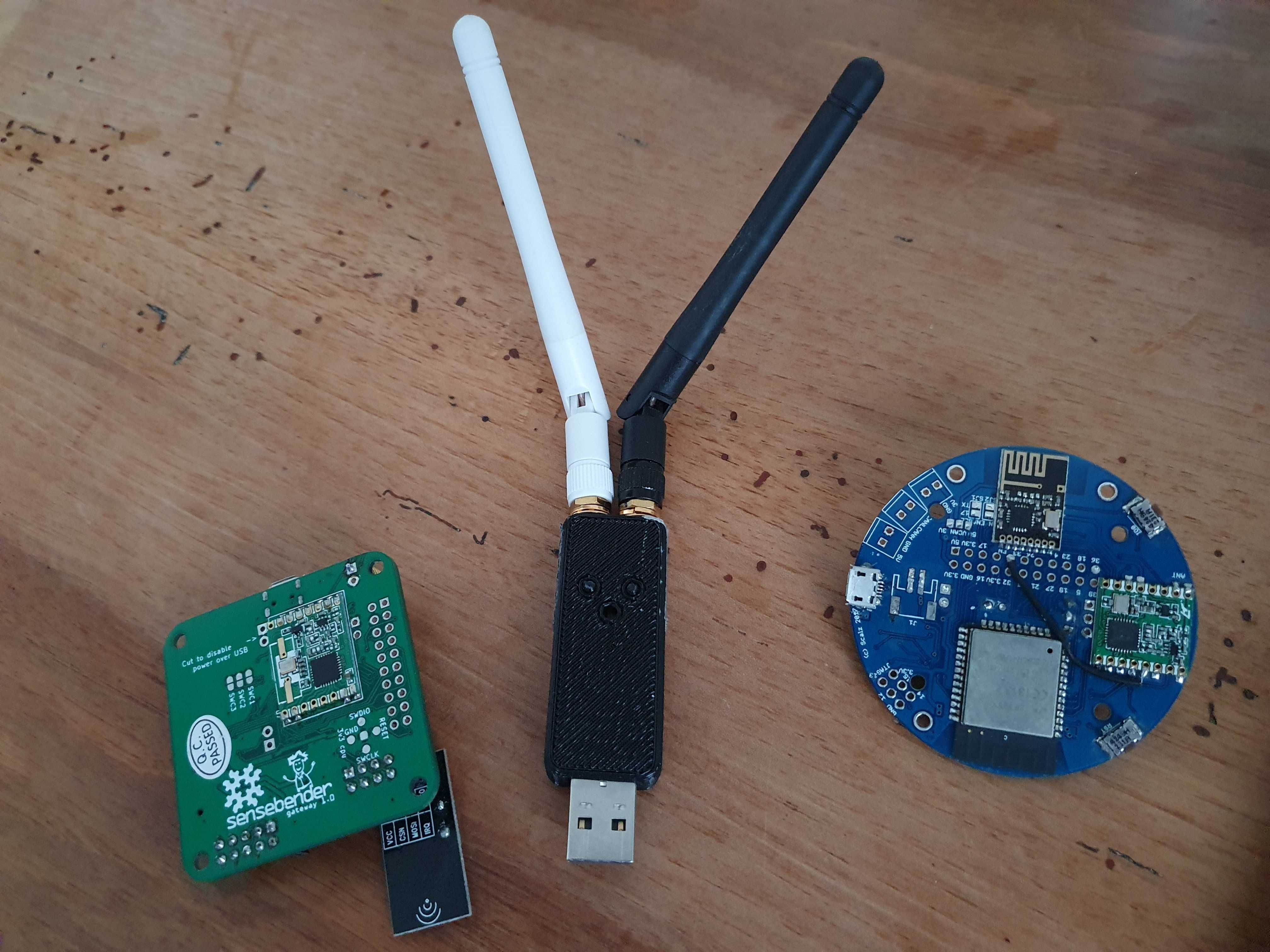
Wait, wait.. what is that USB stick with the dual antennas? Is that a dedicated MySensors gateway device?
// Ah, it's project Janus. AWESOME!
-
I'm trying to use the MY_RFM95_RFM69_COMPATIBILITY options but it does not pass the RFM95_sanityCheck.
Code compile without warning, and gateway is working fine with simple RFM95 driver.
Using esp8266 and arduino 1.8.13.Tue Aug 17 2020 10:48:50 GMT+0100 (CET) : 0;255;3;0;9;67 TSF:LRT:OK Tue Aug 17 2020 10:48:50 GMT+0100 (CET) : 3;0;9;69 TSM:INIT 0;255;3;0;9;71 Tue Aug 17 2020 10:48:50 GMT+0100 (CET) : 0;255;3;0;9;69 TSM:INIT Tue Aug 17 2020 10:48:50 GMT+0100 (CET) : TSF:WUR:MS=0 Tue Aug 17 2020 10:48:50 GMT+0100 (CET) : 0;255;3;0;9;71 TSF:WUR:MS=0 Tue Aug 17 2020 10:48:50 GMT+0100 (CET) : 0;255;3;0;9;74 RFM95:INIT:PIN,CS Tue Aug 17 2020 10:48:50 GMT+0100 (CET) : =15,IQP=4,IQN=4 0;255;3;0;9;78 R Tue Aug 17 2020 10:48:50 GMT+0100 (CET) : 0;255;3;0;9;74 RFM95:INIT:PIN,CS=15,IQP=4,IQN=4 Tue Aug 17 2020 10:48:50 GMT+0100 (CET) : FM95:INIT:RFM69 Tue Aug 17 2020 10:48:50 GMT+0100 (CET) : 0;255;3;0;9;78 RFM95:INIT:RFM69 Tue Aug 17 2020 10:48:50 GMT+0100 (CET) : 0;255;3;0;9;86 RFM95:SRM:MODE=4 Tue Aug 17 2020 10:48:50 GMT+0100 (CET) : 0;255;3;0;9;86 RFM95:SRM:MODE=4 Tue Aug 17 2020 10:48:50 GMT+0100 (CET) : 0;255;3;0;9;220 RFM95:INIT:FREQ=868000000 Tue Aug 17 2020 10:48:50 GMT+0100 (CET) : 0;255;3;0;9;220 RFM95:INIT:FREQ=868000000 Tue Aug 17 2020 10:48:50 GMT+0100 (CET) : 0;255;3;0;9;254 RFM95:PTX:LEVEL=20 Tue Aug 17 2020 10:48:50 GMT+0100 (CET) : 0;255;3;0;9;254 RFM95:PTX:LEVEL=20 Tue Aug 17 2020 10:48:50 GMT+0100 (CET) : 0;255;3;0;9;273 !RFM95:INIT:SANC Tue Aug 17 2020 10:48:50 GMT+0100 (CET) : HK FAIL 0;255;3;0;9;276 !TSM:INIT Tue Aug 17 2020 10:48:50 GMT+0100 (CET) : 0;255;3;0;9;273 !RFM95:INIT:SANCHK FAIL Tue Aug 17 2020 10:48:50 GMT+0100 (CET) : :TSP FAIL 0;255;3;0;9;279 TSM:FAI Tue Aug 17 2020 10:48:50 GMT+0100 (CET) : 0;255;3;0;9;276 !TSM:INIT:TSP FAIL Tue Aug 17 2020 10:48:50 GMT+0100 (CET) : L:CNT=1 0;255;3;0;9;282 TSM:FAIL: Tue Aug 17 2020 10:48:50 GMT+0100 (CET) : 0;255;3;0;9;279 TSM:FAIL:CNT=1 Tue Aug 17 2020 10:48:50 GMT+0100 (CET) : DIS 0;255;3;0;9;285 TSF:TDI:TSL Tue Aug 17 2020 10:48:50 GMT+0100 (CET) : 0;255;3;0;9;282 TSM:FAIL:DIS Tue Aug 17 2020 10:48:50 GMT+0100 (CET) : 0;255;3;0;9;285 TSF:TDI:TSL Tue Aug 17 2020 10:48:50 GMT+0100 (CET) : 0;255;3;0;9;287 RFM95:RSL Tue Aug 17 2020 10:48:50 GMT+0100 (CET) : 0;255;3;0;9;287 RFM95:RSL Tue Aug 17 2020 10:48:50 GMT+0100 (CET) : 0;255;3;0;9;295 RFM95:SRM:MODE=3 Tue Aug 17 2020 10:48:50 GMT+0100 (CET) : 0;255;3;0;9;295 RFM95:SRM:MODE=3 Tue Aug 17 2020 10:49:00 GMT+0100 (CET) : 0;255;3;0;9;10299 TSM:FAIL:RE-IN Tue Aug 17 2020 10:49:00 GMT+0100 (CET) : IT 0;255;3;0;9;10302 TSM:INIT 0; Tue Aug 17 2020 10:49:00 GMT+0100 (CET) : 0;255;3;0;9;10299 TSM:FAIL:RE-INIT Tue Aug 17 2020 10:49:00 GMT+0100 (CET) : 0;255;3;0;9;10302 TSM:INIT Tue Aug 17 2020 10:49:00 GMT+0100 (CET) : 255;3;0;9;10304 RFM95:INIT:PIN,C Tue Aug 17 2020 10:49:00 GMT+0100 (CET) : S=15,IQP=4,IQN=4 0;255;3;0;9;103 Tue Aug 17 2020 10:49:00 GMT+0100 (CET) : 0;255;3;0;9;10304 RFM95:INIT:PIN,CS=15,IQP=4,IQN=4 Tue Aug 17 2020 10:49:00 GMT+0100 (CET) : 09 RFM95:INIT:RFM69 Tue Aug 17 2020 10:49:00 GMT+0100 (CET) : 0;255;3;0;9;10309 RFM95:INIT:RFM69 Tue Aug 17 2020 10:49:00 GMT+0100 (CET) : 0;255;3;0;9;10317 RFM95:SRM:MODE=4 Tue Aug 17 2020 10:49:00 GMT+0100 (CET) : 0;255;3;0;9;10317 RFM95:SRM:MODE=4 Tue Aug 17 2020 10:49:00 GMT+0100 (CET) : 0;255;3;0;9;10451 RFM95:INIT:FREQ=868000000 Tue Aug 17 2020 10:49:00 GMT+0100 (CET) : 0;255;3;0;9;10451 RFM95:INIT:FREQ=868000000 Tue Aug 17 2020 10:49:00 GMT+0100 (CET) : 0;255;3;0;9;10485 RFM95:PTX:LEVEL=20 Tue Aug 17 2020 10:49:00 GMT+0100 (CET) : 0;255;3;0;9;10485 RFM95:PTX:LEVEL=20 Tue Aug 17 2020 10:49:00 GMT+0100 (CET) : 0;255;3;0;9;10504 !RFM95:INIT:SA Tue Aug 17 2020 10:49:00 GMT+0100 (CET) : NCHK FAIL 0;255;3;0;9;10507 !TSM Tue Aug 17 2020 10:49:00 GMT+0100 (CET) : 0;255;3;0;9;10504 !RFM95:INIT:SANCHK FAIL Tue Aug 17 2020 10:49:00 GMT+0100 (CET) : :INIT:TSP FAIL 0;255;3;0;9;10511 Tue Aug 17 2020 10:49:00 GMT+0100 (CET) : 0;255;3;0;9;10507 !TSM:INIT:TSP FAIL Tue Aug 17 2020 10:49:00 GMT+0100 (CET) : TSM:FAIL:CNT=2 0;255;3;0;9;10514 Tue Aug 17 2020 10:49:00 GMT+0100 (CET) : 0;255;3;0;9;10511 TSM:FAIL:CNT=2 Tue Aug 17 2020 10:49:00 GMT+0100 (CET) : TSM:FAIL:DIS 0;255;3;0;9;10516 T Tue Aug 17 2020 10:49:00 GMT+0100 (CET) : 0;255;3;0;9;10514 TSM:FAIL:DIS Tue Aug 17 2020 10:49:00 GMT+0100 (CET) : SF:TDI:TSL 0;255;3;0;9;10519 RFM95:RSL Tue Aug 17 2020 10:49:00 GMT+0100 (CET) : 0;255;3;0;9;10516 TSF:TDI:TSL Tue Aug 17 2020 10:49:00 GMT+0100 (CET) : 0;255;3;0;9;10519 RFM95:RSL Tue Aug 17 2020 10:49:00 GMT+0100 (CET) : 0;255;3;0;9;10527 RFM95:SRM:MODE=3 Tue Aug 17 2020 10:49:00 GMT+0100 (CET) : 0;255;3;0;9;10527 RFM95:SRM:MODE=3 -
Thanks @tekka
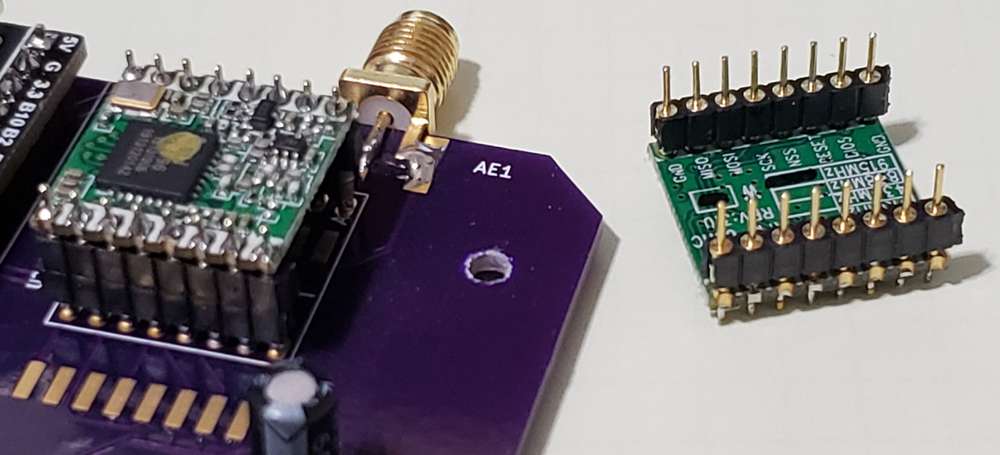
This is awesome and came along at the perfect time. I have 4 networks because of experimenting over the years and have been meaning to clean up the rats-nest of wires that is my current set of serial gateways. Enter Multi-Transport.
I made a gateway with NRF24 and RFM95 (915Mhz) running off an STM32F411 black pill. Worked right off the bat.
Now I just need to duplicate for RFM69 and RFM95(433Mhz).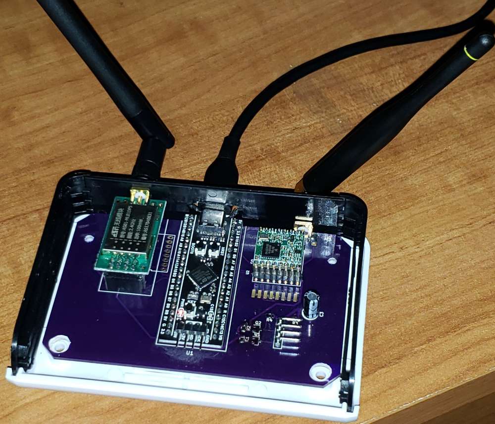
-
Thanks @tekka
This is awesome and came along at the perfect time. I have 4 networks because of experimenting over the years and have been meaning to clean up the rats-nest of wires that is my current set of serial gateways. Enter Multi-Transport.
I made a gateway with NRF24 and RFM95 (915Mhz) running off an STM32F411 black pill. Worked right off the bat.
Now I just need to duplicate for RFM69 and RFM95(433Mhz).
Hello! It looks like you're interested in this conversation, but you don't have an account yet.
Getting fed up of having to scroll through the same posts each visit? When you register for an account, you'll always come back to exactly where you were before, and choose to be notified of new replies (either via email, or push notification). You'll also be able to save bookmarks and upvote posts to show your appreciation to other community members.
With your input, this post could be even better 💗
Register Login