Skip to content
  • OpenHardware.io
  • Categories
  • Recent
  • Tags
  • Popular
Skins
  • Light
  • Brite
  • Cerulean
  • Cosmo
  • Flatly
  • Journal
  • Litera
  • Lumen
  • Lux
  • Materia
  • Minty
  • Morph
  • Pulse
  • Sandstone
  • Simplex
  • Sketchy
  • Spacelab
  • United
  • Yeti
  • Zephyr
  • Dark
  • Cyborg
  • Darkly
  • Quartz
  • Slate
  • Solar
  • Superhero
  • Vapor

  • Default (No Skin)
  • No Skin
Collapse
Brand Logo
  1. Home
  2. General Discussion
  3. nRF24L01+PA+LNA
  • Getting Started
  • Controller
  • Build
  • Hardware
  • Download/API
  • Forum
  • Store

nRF24L01+PA+LNA

Scheduled Pinned Locked Moved General Discussion
35 Posts 9 Posters 39.1k Views 4 Watching
  • Oldest to Newest
  • Newest to Oldest
  • Most Votes
Reply
  • Reply as topic
Log in to reply
This topic has been deleted. Only users with topic management privileges can see it.
  • D dzairo

    @AWI of course .. he ask for voltage converter.. from 5V to 3.3V ..

    AWIA Offline
    AWIA Offline
    AWI
    Hero Member
    wrote on last edited by
    #21

    @dzairo Better to be safe ;-)

    1 Reply Last reply
    0
    • AWIA AWI

      @doblanch Sorry for confusing you. If you are using the Uno the 5V pin can deliver about 450mA if powered from USB and 650mA if powered from power jack. This is more than enough to supply the "Socket Adapter Board" which has a powerfull regulator. The 3.3V pin on the Uno can only supply 40mA.

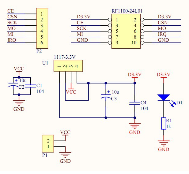
      There is nothing wrong with the supply you mentioned either. The converter board is more convenient to connect and includes the capacitors (ceramic & tantalum) needed for a stable supply . Schematic below:

      upload-484c79ac-6b0d-4723-9674-ccff475064ae

      D Offline
      D Offline
      doblanch
      wrote on last edited by doblanch
      #22

      @AWI That's clear then.... I didn't know that 5V on uno can draw 450ma... ON their website, they precise only I/O and 3.3V... From now it's very clear. I will use the 5V pin, with "something" to reduce it to 3.3V...
      I have this in stock : http://www.ebay.com/itm/Mini-3A-DC-DC-Converter-Adjustable-Step-down-Power-Supply-Module-replace-LM2596s-/261328784505?ssPageName=ADME:L:OU:FR:3160
      a power down module, IN="5V" OUT-"adjustable (including 3.3V)"
      Do you know for the nano the +5V max draw ?
      Thank for your help, grandly appreciated.

      AWIA 1 Reply Last reply
      0
      • D doblanch

        @AWI That's clear then.... I didn't know that 5V on uno can draw 450ma... ON their website, they precise only I/O and 3.3V... From now it's very clear. I will use the 5V pin, with "something" to reduce it to 3.3V...
        I have this in stock : http://www.ebay.com/itm/Mini-3A-DC-DC-Converter-Adjustable-Step-down-Power-Supply-Module-replace-LM2596s-/261328784505?ssPageName=ADME:L:OU:FR:3160
        a power down module, IN="5V" OUT-"adjustable (including 3.3V)"
        Do you know for the nano the +5V max draw ?
        Thank for your help, grandly appreciated.

        AWIA Offline
        AWIA Offline
        AWI
        Hero Member
        wrote on last edited by
        #23

        @doblanch The Nano has an 78M05 regulator, should be able to supply 500mA (including the power for the MCU and FTDI chip, So more than enough power to power your step-down. Let us know if your problem is solved.

        D 1 Reply Last reply
        0
        • AWIA AWI

          @doblanch The Nano has an 78M05 regulator, should be able to supply 500mA (including the power for the MCU and FTDI chip, So more than enough power to power your step-down. Let us know if your problem is solved.

          D Offline
          D Offline
          doblanch
          wrote on last edited by doblanch
          #24

          @AWI Hello, I put a stepdown module on the both end, added a capacitor. I change the myconfig.h file to put RF24_PA_MAX on RF24_PA_LEVEL and RF24_PA_LEVEL_GW . The result was a little bit better, I'm not even sure :-( . But from now, result are good, I switch back my current antenna by the original one delivered with the module NRF24+.
          in fact, I installed some big antenna (I have some spare with my routed wifi network), but I think it was a mistake. With the NRF24 bulk antenna, it works really better, I have some others tests to do...I will keep you informed in the coming days. thanks again for you help

          1 Reply Last reply
          0
          • W Offline
            W Offline
            wico2002
            wrote on last edited by
            #25

            Hi, i have the same problem. Bought a pa+lna radio with black antenna and only work if i touch the antenna or the radio's pcb, else the data if not sent at all. i added only a 200uf capacitor. Even with the breadboard power supply, to have a separate 3.3v it dont work. My basic nrf24l01+ is working well (except the range) but not the pre amplified one.

            Any one have ideas ?

            OitzuO 1 Reply Last reply
            0
            • W wico2002

              Hi, i have the same problem. Bought a pa+lna radio with black antenna and only work if i touch the antenna or the radio's pcb, else the data if not sent at all. i added only a 200uf capacitor. Even with the breadboard power supply, to have a separate 3.3v it dont work. My basic nrf24l01+ is working well (except the range) but not the pre amplified one.

              Any one have ideas ?

              OitzuO Offline
              OitzuO Offline
              Oitzu
              wrote on last edited by
              #26

              @wico2002 try adding a layer of plastic wrap followed by a layer of tin foil around the pcb.
              In this process don't let the tinfoil touch the pcb or any connection. This will basically create a farraday cage around your pcb.
              I've learned the hard way that the boosted modules can sometimes, at high power levels, interfere with itself.

              1 Reply Last reply
              0
              • W Offline
                W Offline
                wico2002
                wrote on last edited by
                #27

                @Oitzu I try running it at a lower PA level, set in the code, don't know if it helped or not. I also found if I keep the antenna straight (my antenna plug is pointing on the side, so let say 0 degrees) or at 90 degrees no data is sent but if it is fold at 45 degree the data seems to be sent good even if I don't touch the radio (but still don't know if I got a good range or not). seems to work better without the antenna plugged in ...

                i'll try your trick

                1 Reply Last reply
                0
                • OitzuO Offline
                  OitzuO Offline
                  Oitzu
                  wrote on last edited by
                  #28

                  @wico2002 that's all really the typical behaviour i observed, too.
                  In reality the module sends the data but will never receive the "ack" because the signal overloads, due to interferences, the nrf24l01+ on the board.
                  Holding your hand arround the pcb or antenna or unplugging the antenna weakens the signal and stops this behaviour.

                  See also: http://forum.mysensors.org/topic/1877/2-x-nrf24l01-pa-lna-with-rf24_pa_max/12

                  1 Reply Last reply
                  0
                  • W Offline
                    W Offline
                    wico2002
                    wrote on last edited by
                    #29

                    Thank you for this link.

                    I will reply in that topic to continue the same subject.

                    1 Reply Last reply
                    0
                    • J Offline
                      J Offline
                      johnr
                      wrote on last edited by
                      #30

                      Hi,

                      I built my serial gateway like two years ago and it is running smooth with nRF24L01+ PA+ LNA

                      I remember a had to fiddle with the power setting. Since I am now replacing it with a Ethernet gateway, I plan to use a ld1117v33 to power the radio. It can give 800ma so it should be suffcient to runt it without power issues.

                      Did anyone have experience with this? Do you recommend I should set Pa_level to high or Max?

                      OitzuO 1 Reply Last reply
                      0
                      • J johnr

                        Hi,

                        I built my serial gateway like two years ago and it is running smooth with nRF24L01+ PA+ LNA

                        I remember a had to fiddle with the power setting. Since I am now replacing it with a Ethernet gateway, I plan to use a ld1117v33 to power the radio. It can give 800ma so it should be suffcient to runt it without power issues.

                        Did anyone have experience with this? Do you recommend I should set Pa_level to high or Max?

                        OitzuO Offline
                        OitzuO Offline
                        Oitzu
                        wrote on last edited by
                        #31

                        @johnr you should give it a try. 800mA is more than enough.
                        But don't forget to shield the module probably otherwise you will have the above mentioned interferences.

                        Site note: The max setting is actually a special setting for nrf24l01+ clones that have a higher output setting on a special register then the original nrf24l01+ chips. But regardless the chip you can use this. A original nrf24l01+ will simply ignore the register flag.

                        karl261K 1 Reply Last reply
                        0
                        • OitzuO Oitzu

                          @johnr you should give it a try. 800mA is more than enough.
                          But don't forget to shield the module probably otherwise you will have the above mentioned interferences.

                          Site note: The max setting is actually a special setting for nrf24l01+ clones that have a higher output setting on a special register then the original nrf24l01+ chips. But regardless the chip you can use this. A original nrf24l01+ will simply ignore the register flag.

                          karl261K Offline
                          karl261K Offline
                          karl261
                          wrote on last edited by
                          #32

                          @Oitzu Is that so? How could I find out if my nrf accepts the max setting? Maybe it is not using it at all. What is the default then? I also saw that @GertSanders was recommending to use the "high" setting as maximum. Maybe that is why?

                          1 Reply Last reply
                          0
                          • OitzuO Offline
                            OitzuO Offline
                            Oitzu
                            wrote on last edited by
                            #33

                            @karl261 the MAX Setting is the HIGH setting + a extra bit. The extra bit is ignored by the original nrf24l01+ chips. Some nrf24l01+ clones (also known as the SI24R1) are using this bit to switch into a higher mode.

                            karl261K 1 Reply Last reply
                            0
                            • OitzuO Oitzu

                              @karl261 the MAX Setting is the HIGH setting + a extra bit. The extra bit is ignored by the original nrf24l01+ chips. Some nrf24l01+ clones (also known as the SI24R1) are using this bit to switch into a higher mode.

                              karl261K Offline
                              karl261K Offline
                              karl261
                              wrote on last edited by
                              #34

                              @Oitzu Ok, so, if I understand correctly, then, if I set the nrf to max, and it will ignore the flag, it will be at high, correct?

                              Another question: I have a battery sensor with a +pa+lna because I installed a little weather station in a bird house... Concerning battery life, would you run it at min or low?

                              1 Reply Last reply
                              0
                              • OitzuO Offline
                                OitzuO Offline
                                Oitzu
                                wrote on last edited by
                                #35

                                @karl261 with the original nrf24l01+ modules this is correct, yes.
                                To save battery use the lowest setting that still works without transmitting errors.

                                1 Reply Last reply
                                0
                                Reply
                                • Reply as topic
                                Log in to reply
                                • Oldest to Newest
                                • Newest to Oldest
                                • Most Votes


                                4

                                Online

                                11.7k

                                Users

                                11.2k

                                Topics

                                113.0k

                                Posts


                                Copyright 2019 TBD   |   Forum Guidelines   |   Privacy Policy   |   Terms of Service
                                • Login

                                • Don't have an account? Register

                                • Login or register to search.
                                • First post
                                  Last post
                                0
                                • OpenHardware.io
                                • Categories
                                • Recent
                                • Tags
                                • Popular