CR2032 coin cells - expected life?
-
Hi! Im having issues when testing MySensors nodes with CR2032.
BOD are set to 2.3 but it seems like the node dies around 2,8-2,9 and it does not last very long.
Its a "naked" testnode, nrf24, sleep active, minial current drain.First, is it to be expected that these batteries does not work below 2.8v?
Any other tips?@sundberg84 I noticed similar issues with my nodes. Given the high internal resistance of coin batteries, there is actually a significant voltage drop during high current scenarios (radio transmission). Enough of a drop to trigger brownout, which then leads to brownout loops.
I recommend disabling status LEDs, and using large capacitor(s) (200uF+), ideally ceramic. I'd also drop BOD to 1.8v.
Also make sure you're sleeping between transmissions (~5 sec) to make sure the capacitors have enough time to recharge.
-
When are you measuring the battery voltage? Before or after a transmission? My guess is before. The better measurement is if you measure immediately after transmission, before battery recovery, and then save the value for reporting during the next subsequent transmission. That's especially true for coincells, whose voltage tends to droop a lot after pulling a current.
@NeverDie - I measure after - but I let the battery recover from the transmission, so you have a valid point.
@BearWithBeard - Thanks - if you can do it, I can :)
@ncollins - a big capasitor sounds lika a good idea, 1.8v bod I have and also sleep (5 minutes). Thanks for the input, sounds like a plan ahead. -
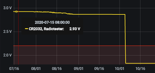
I recently completed an experiment with 2 nearly identical nodes and had very good results just using @NeverDie MySleepPrepare() without any other real effort to reduce power consumption.
The nodes were NRF52832 and BME280. One with a CR2032 Coin cell and the other with a LiFePo4 (AAA size). The CR2032 lasted a little longer in this application.
I stopped when the CR2032 dropped below 1.8V because that was the low voltage rating for both the processor and the BME, but the node still appeared to be working normally.Vertical axis is volts. Horizontal axis is days.
-
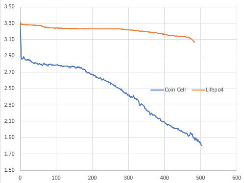
@nagelc Just wondering what boards and what bootloaders you are all using for battery nodes as I will need to make a few soon.
-
@skywatch These used the Fanstel BT832. Not sure about the bootloader. I just programmed them as they came. I programmed them using Arduino and the MySensors MyBoardNRF5 files, and a black magic probe for the programmer.
-
I've been doing an experiment based on my custom board (https://github.com/buxtronix/mys-pro-mini) which is essentially an Arduino-pro-mini compatible pinout with NRF radio and SHT31 temp/humidity sensor built in.
It can take a CR2032 directly on board.
I've been running two identical sensors, the only difference being that one uses the INTRC clock, and the other uses an 8MHz Xtal. Update rate is about 1/min.
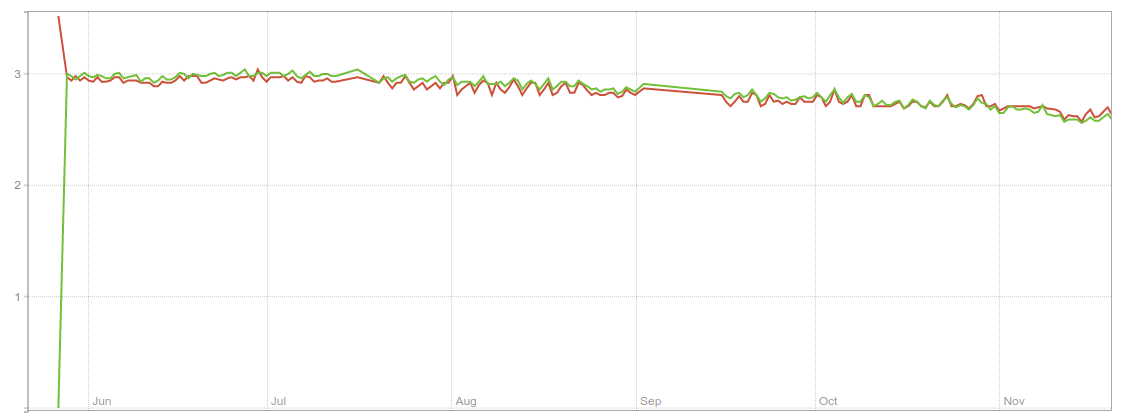
As you can see, I'm nearly 6 months in and I think I should be able to get to a year. Interestingly, there is no notable difference in battery between the two clock sources - it's otherwise been widely believed that xtal consumes more power than intrc.
The only low-power prep I'm doing in the code is to disable the ADC and set all unused floating pins to output mode. Standard arduino bootloader, BOD disabled.
-
I've been doing an experiment based on my custom board (https://github.com/buxtronix/mys-pro-mini) which is essentially an Arduino-pro-mini compatible pinout with NRF radio and SHT31 temp/humidity sensor built in.
It can take a CR2032 directly on board.
I've been running two identical sensors, the only difference being that one uses the INTRC clock, and the other uses an 8MHz Xtal. Update rate is about 1/min.
As you can see, I'm nearly 6 months in and I think I should be able to get to a year. Interestingly, there is no notable difference in battery between the two clock sources - it's otherwise been widely believed that xtal consumes more power than intrc.
The only low-power prep I'm doing in the code is to disable the ADC and set all unused floating pins to output mode. Standard arduino bootloader, BOD disabled.
-
Good idea to measure battery voltage after an RF transmission, not before ... never thought of that.
I have built window sensors that last more than 36 months on one CR2032. I usually set the brownout threshold to 1.8V, not 2.7V, and then replace the battery when the voltage drops below ~2.2V.
You have to be careful not to power any sensors while the node is asleep, that also applies to the lowly reed switch windows sensor! If you just connect it to an input pin and use the internal pull-up of the ATmega processor, then you have a current flowing all the time, when the window is closed and therefore the reed switch inside the sensor is closed. That current is higher than the sleep mode power consumption of the whole processor!
I can see why internal clock vs 8 MHz crystal doesn't make a difference -- most of the time, the processor will be asleep with all clocks stopped, and a stopped 8 MHz crystal oscillator consumes as much power as a stopped internal RC oscillator ...
You can find more details about what to watch out for, and some measurements with different configurations, here.
-
@canyouhearmenow : in stead of the internal pull-up resistor for the reed contact, I used an external one of 3.3MOhm. Is that a good idea?
-
An alternative is to do pullup via an output pin. So connect the switch like this:
D2 --- 47k --- D1 --- reed switch --- GNDDisable D1's pullups. While sleeping set D2 low to eliminate all power draw, then after wakeup you can set D2 high, wait a few ms and then measure D1. Once done, set D2 low again.
You can't do interrupt based sensing this way but works for polling.
-
@canyouhearmenow : in stead of the internal pull-up resistor for the reed contact, I used an external one of 3.3MOhm. Is that a good idea?
@Michiel-van-der-Wulp using a megaohms pull-up resistor solves the problem with current consumption, but now you have an input that is more susceptible to interference, because it is high impedance.
Hello! It looks like you're interested in this conversation, but you don't have an account yet.
Getting fed up of having to scroll through the same posts each visit? When you register for an account, you'll always come back to exactly where you were before, and choose to be notified of new replies (either via email, or push notification). You'll also be able to save bookmarks and upvote posts to show your appreciation to other community members.
With your input, this post could be even better 💗
Register Login