Irrigation Controller (up to 16 valves with Shift Registers)
-
Is there a way to use domoticz to connect with it and on/off this irrigation system? How to achive this?
My domoticz is running on raspberry pi 0.
Yes, i've had to manually set the valve runtimes on the ardunio code, because its not possible to pass the runtime variable etc, this is from the one i''ve got built. runtime is 1min, but you can edit as required.
else if (message.type == V_VAR1) { int variable1 = 60000; // atoi(message.data);// RUN_ALL_ZONES time DEBUG_PRINT(F("Recieved variable1 valve:")); DEBUG_PRINT(i); DEBUG_PRINT(F(" = ")); DEBUG_PRINTLN(variable1); if (variable1 != allZoneTime[i]) { allZoneTime[i] = variable1; zoneTimeUpdate = true; } } else if (message.type == V_VAR2) { int variable2 = 60000; //atoi(message.data);// RUN_SINGLE_ZONE time DEBUG_PRINT(F("Recieved variable2 valve:")); DEBUG_PRINT(i); DEBUG_PRINT(F(" = ")); DEBUG_PRINTLN(variable2); if (variable2 != valveSoloTime[i]) { valveSoloTime[i] = variable2; zoneTimeUpdate = true; } } -
Thanks for posting, Mark. I was getting nuts figuring out what was the problem with my controller that was only activating 1sec each phase. I didn't implement it because that problem.
-
Thanks for posting, Mark. I was getting nuts figuring out what was the problem with my controller that was only activating 1sec each phase. I didn't implement it because that problem.
@Sergio-Rius no problem, i had plenty of issues trying to get this to work with openhab before i changed controller :)
-
So I have been thinking of building one of these. I have just ordered an 8 channel relay board from ebay. http://www.ebay.com/itm/5V-8-Channel-Relay-Board-Module-for-Arduino-Raspberry-Pi-ARM-AVR-DSP-PIC-MUC-/262472832393?hash=item3d1c999589:g:sDEAAOSwnFZXVj2p . I have been trying to sift through this thread and am not seeing what I am looking for. Does this project take into account a pump start relay? If not, I am wondering the best way to handle this. I only have 4 zones in my irrigation setup, so I could certainly use one of the relay channels for that if it is written into the sketch. One thought I had to save extra processing on the sketch in dealing with the shift register would be to put a diode on each output that would funnel to a single point, so whenever any relay is turned on the pump start connection point would go active. I would assume that something has already been calculated in for this, but I din't see anything.
Thanks for the great project. The Youtube video for this is actually what got me started with MySensors in the first place.
-
I'm going down the diodes route... another channel to trigger it is tricky to deal with unless you use normally off relays and use the code earlier in this thread. I tried to use it but use normally on relays so going for diodes.
K.I.S.S - keep it simple stupid ;) no point making it harder for you if you have a workaround on the table :)
-
@Mark Jefford I can go that route, I just didn't know if someone already had that factored in to the project already. After thinking about it since I posted this, I could also go the route of using another single digital channel and wire it to one of the relays. Going that route would give me a couple things:
- One I could turn on the pump independent of a zone because I have a faucet connected to the setup that I can use. Currently I have to turn on a zone to use the faucet.
- Two, I could poll the state of the pump by checking the state of the one channel.
-
@Sergio-Rius no problem, i had plenty of issues trying to get this to work with openhab before i changed controller :)
@Mark-Jefford I have the same issue. My system can't pass verifications for clock and valve data when I first plugged in because I don't know how to use this programs (Openhab, domoticz, etc.). Thank you!
-
@Lars65 Take a look at lines 663-667. I haven't tested this but it should be something similar to this:
lcd.print(hour() < 10 ? F(" ") : F("")); lcd.print(hour()); lcd.print(minute() < 10 ? F(":0") : F(":")); lcd.print(minute()); //lcd.print(isAM() ? F("am") : F("pm")); -
@Lars65 Take a look at lines 663-667. I haven't tested this but it should be something similar to this:
lcd.print(hour() < 10 ? F(" ") : F("")); lcd.print(hour()); lcd.print(minute() < 10 ? F(":0") : F(":")); lcd.print(minute()); //lcd.print(isAM() ? F("am") : F("pm")); -
Does anyone already made a pcb for this? My board keeps loosing it's "bridging" wires. They rot and fall near the solder.
@Sergio-Rius Where do you have your controller located? I have had mine running for over a year now and haven't had any issues. Maybe you need to put it into a waterproof case?
To answer your question though, no, I don't believe anyone has created a PCB for this.
-
Hello Gentlemen, new to this board as well as new to micro electrics. Started this Irrigation Controller about a two weeks ago, after finding Pete B’s U tube video on this project. Got all the parts and have started building by following Pete B’s video. Have a few part questions and am not very literal with the nomenclature.
- This 4.7uF 50V 20% Axial-Lead Electrolytic Capacitor goes on which end or pins on the
- Have a FT232RL FTDI USB 3.3V 5.5V to TTL Serial Adapter Module for Mini Port that is different than Pete’s.
Not sure how to post JPEG's so this is the problem I am having.
0_1468546122072_7-14-16 Hello Gentlemen help.docx
The Pins on the ftdi are different than on Pete’s board, in that I cannot find the info for the double GND on the Arduino Pro Mini.
Any guidance of will be appreciated.
Respectfully RJ Myers -
Hello Gentlemen, new to this board as well as new to micro electrics. Started this Irrigation Controller about a two weeks ago, after finding Pete B’s U tube video on this project. Got all the parts and have started building by following Pete B’s video. Have a few part questions and am not very literal with the nomenclature.
- This 4.7uF 50V 20% Axial-Lead Electrolytic Capacitor goes on which end or pins on the
- Have a FT232RL FTDI USB 3.3V 5.5V to TTL Serial Adapter Module for Mini Port that is different than Pete’s.
Not sure how to post JPEG's so this is the problem I am having.
0_1468546122072_7-14-16 Hello Gentlemen help.docx
The Pins on the ftdi are different than on Pete’s board, in that I cannot find the info for the double GND on the Arduino Pro Mini.
Any guidance of will be appreciated.
Respectfully RJ Myers@Lars65 No, not yet. It's on the list but it will probably be a little while before I get to it.
@Ngwpower To add pictures you just have to drag and drop into the edit window. They will automatically upload.
-
Can you provide more info here? I'm not sure what you're asking.
-
Both of my FTDI adapters connect into the Pro Mini straight across (the wires don't get crossed when connecting. The key thing is TX on one side should go to RX on the other (and vice versa) then the other 4 wires line up from there. So, you almost have it correct in your picture but the TX and RX are switched. Just start from the DTR and go straight across.
-
Thank You, petewill I adjusted the wiring!
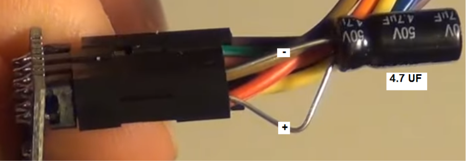
This is the picture for the 4.7 UF that has me baffled of where to insert into the radio. Being color blind really hurts with wiring. And rather ask than fry another project....
RJ -
Thank You, petewill I adjusted the wiring!
This is the picture for the 4.7 UF that has me baffled of where to insert into the radio. Being color blind really hurts with wiring. And rather ask than fry another project....
RJ@Ngwpower
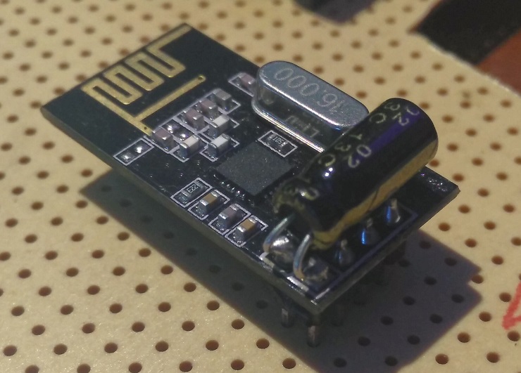
EDIT: My condenser is 10uF / 63v
-
Does this sketch still work with the current Mysensors libraries?
I lost my working environment so I had to build a new one. I downloaded the MySensors libraries and the sketch throws me an error not finding MySensor.h. The file is not at the libraries folder, but MySensorS.h
If adding this later (used at the samples) the compilation throws an error:W:\....\MySensors_Arduino\arduino-1.6.9\portable\sketchbook\libraries\MySensors/MySensors.h:287:4: error: #error No forward link or gateway feature activated. This means nowhere to send messages! Pretty pointless. #error No forward link or gateway feature activated. This means nowhere to send messages! Pretty pointless. ^ exit status 1 Error compilación en tarjeta Arduino Nano.``` Does make sense for anyone? -
@Ngwpower
EDIT: My condenser is 10uF / 63v
@Sergio-Rius
Than You for the clarfication & picture worth thousands of words.
RJ