Irrigation Controller (up to 16 valves with Shift Registers)
-
@Anticimex Sorry, but I don't follow the development code on a day basis, I was not aware of this feature.
Anyways, a common psk will be like grease. Any psk would be better than no-one. :)Let me explain: I was thinking on a small Pc program that you can select options (NodeManager) and then burn the chip by a click of a button. But also crossed my mind the possibility that a user, with a running secure network, wanted to get a sensebender gateway already programmed. It would be no use.
I was thinking on a way of "programming the crypto chip" separately from the cpu program. I don't know if it clearer now or I made it worse.
@Sergio-Rius I am still a bit confused.
A default PSK would be the same for everyone so how is that better than no one?
Also, nrf24 radios have problem with full size payloads so enabling signing by default would give some users radio problems by default as well. It is not a problem with signing, it is a problem with the radio. -
@Anticimex Sorry, but I don't follow the development code on a day basis, I was not aware of this feature.
Anyways, a common psk will be like grease. Any psk would be better than no-one. :)Let me explain: I was thinking on a small Pc program that you can select options (NodeManager) and then burn the chip by a click of a button. But also crossed my mind the possibility that a user, with a running secure network, wanted to get a sensebender gateway already programmed. It would be no use.
I was thinking on a way of "programming the crypto chip" separately from the cpu program. I don't know if it clearer now or I made it worse.
@Sergio-Rius the crypto chip (I prefer the term authentication chip as it does not do cryptography) is connected to the MCU so you need a program on the MCU to program the chip in one way or another. Lest you program the chip before soldering it to the board. And I think the personalization procedure (improved in beta) is documented and simplified enough so that having a separate pc program and do off board programming of the chip would be a far more complicated procedure for "non programmers".
Do you feel secure today? No? Start requiring some signatures and feel better tomorrow ;)
-
@Sergio-Rius the crypto chip (I prefer the term authentication chip as it does not do cryptography) is connected to the MCU so you need a program on the MCU to program the chip in one way or another. Lest you program the chip before soldering it to the board. And I think the personalization procedure (improved in beta) is documented and simplified enough so that having a separate pc program and do off board programming of the chip would be a far more complicated procedure for "non programmers".
@Anticimex I'd add that encryption and signing are more advanced features and should be dealt once newbies get used to the mysensors framework and after they get used to how to debug, otherwise it would also add too much complexity
-
@Anticimex I'd add that encryption and signing are more advanced features and should be dealt once newbies get used to the mysensors framework and after they get used to how to debug, otherwise it would also add too much complexity
-
@Anticimex I'd add that encryption and signing are more advanced features and should be dealt once newbies get used to the mysensors framework and after they get used to how to debug, otherwise it would also add too much complexity
Guys if you look I been on here for about a year so yes I been reading alot before I started to build. An been look at YouTube video about code and all this.
I have given up on this one for now and I got an pre build one from a another site he have an set by set with networks and so on. I be back later. After I get openhab and MQTT worked out. As I going to be using esp8266 and the MQTT. -
Hi
Having some issues with the sketch compiling, I am using the 1.84 arduino and the latest libraries 2.1.1 mysensors. I have not made any changes to the sketch at all. Debug is remarked out.
Any help or guidance would be greatly appreciated .
Arduino: 1.8.4 (Windows 10), Board: "Arduino Pro or Pro Mini, ATmega328P (5V, 16 MHz)"
In file included from C:\Users\Audrey\AppData\Local\Temp\arduino_modified_sketch_110779\IrrigationController.ino:95:0:
C:\Users\Audrey\Documents\Arduino\libraries\MySensors/MySensors.h:328:2: error: #error No forward link or gateway feature activated. This means nowhere to send messages! Pretty pointless.
#error No forward link or gateway feature activated. This means nowhere to send messages! Pretty pointless.
^
C:\Users\Audrey\AppData\Local\Temp\arduino_modified_sketch_110779\IrrigationController.ino:99:31: fatal error: LiquidCrystal_I2C.h: No such file or directory
#include <LiquidCrystal_I2C.h>
^compilation terminated.
exit status 1
Error compiling for board Arduino Pro or Pro Mini.This report would have more information with
"Show verbose output during compilation"
option enabled in File -> Preferences. -
Hi
Having some issues with the sketch compiling, I am using the 1.84 arduino and the latest libraries 2.1.1 mysensors. I have not made any changes to the sketch at all. Debug is remarked out.
Any help or guidance would be greatly appreciated .
Arduino: 1.8.4 (Windows 10), Board: "Arduino Pro or Pro Mini, ATmega328P (5V, 16 MHz)"
In file included from C:\Users\Audrey\AppData\Local\Temp\arduino_modified_sketch_110779\IrrigationController.ino:95:0:
C:\Users\Audrey\Documents\Arduino\libraries\MySensors/MySensors.h:328:2: error: #error No forward link or gateway feature activated. This means nowhere to send messages! Pretty pointless.
#error No forward link or gateway feature activated. This means nowhere to send messages! Pretty pointless.
^
C:\Users\Audrey\AppData\Local\Temp\arduino_modified_sketch_110779\IrrigationController.ino:99:31: fatal error: LiquidCrystal_I2C.h: No such file or directory
#include <LiquidCrystal_I2C.h>
^compilation terminated.
exit status 1
Error compiling for board Arduino Pro or Pro Mini.This report would have more information with
"Show verbose output during compilation"
option enabled in File -> Preferences.@Newzwaver
First, the "error No forward link or gateway feature activated. This means nowhere to send messages! Pretty pointless."
this means that you most likely don't have a radio or other gateway connection type defined. Basically you need to tell it how it is going to communicate to your controller and/or other devices. You need to remove the // from one of the options./ Enable and select radio type attached //#define MY_RADIO_NRF24 //#define MY_RADIO_RFM69 //#define MY_RS485Next, do you have the LiquidCrystal library installed? If so, is it the correct one? My guess is that it isn't since it cannot find the LiquidCrystal_I2C.h file. You should get the one from GitHub. Start there and let us know what happens.
-
Hello,
Has anybody succeeded in adapting Irrigation Controller to OpenHAB2?
Although a long time experienced programmer, I am new to domotic and begining to explore the subject. OpenHAB seems to be a nicely architectured software, and well documented. The bindings for MySensors define a number of devices types. Which one would be the best choice in that case? How could the Irrigation Controller sketch be adaptated? Is it possible to add V_VAR1..3 to light thing type?
Thank you for your help.
I'm replying to myself. After reading OpenHAB doc, I managed to have all functionnalities working without changing the Irrigation Controller code.
I cannot put the whole howto here, but basically I created .things and .items files listed here. In addition, I installed the MySensor gateway on the same Raspberry Pi as OpenHAB, connected as an Ethernet gateway. I also installed MapDB persistence, as explained in the documentation./etc/openhab2/things/house.things
Bridge mysensors:bridge-eth:gateway [ ipAddress="127.0.0.1", tcpPort=5003, sendDelay=200 ] {
        light           all_zones       "Toutes zones"  [ nodeId=1, childId=0 ]
        rgbLight        zone1           "Zone 1"        [ nodeId=1, childId=1 ]
        rgbLight        zone2           "Zone 2"        [ nodeId=1, childId=2 ]
        rgbLight        zone3           "Zone 3"        [ nodeId=1, childId=3 ]
        rgbLight        zone4           "Zone 4"        [ nodeId=1, childId=4 ]
        rgbLight        zone5           "Zone 5"        [ nodeId=1, childId=5 ]
        rgbLight        zone6           "Zone 6"        [ nodeId=1, childId=6 ]
        rgbLight        zone7           "Zone 7"        [ nodeId=1, childId=7 ]
        rgbLight        zone8           "Zone 8"        [ nodeId=1, childId=8 ]
  }
/etc/openhab2/items/house.items
Group House
Group Irrigation        <water> (House)
Group AllZones          <water> (Irrigation)
Group Zone1             <water> (Irrigation)
Group Zone2             <water> (Irrigation)
Group Zone3             <water> (Irrigation)
Group Zone4             <water> (Irrigation)
Group Zone5             <water> (Irrigation)
Group Zone6             <water> (Irrigation)
Group Zone7             <water> (Irrigation)
Group Zone8             <water> (Irrigation)
Switch  zone0_s "On/Off"                (AllZones)      { channel="mysensors:light:gateway:all_zones:status" }
Switch  zone1_s "On/Off"                        (Zone1)         { channel="mysensors:rgbLight:gateway:zone1:status" }
Number  zone1_1 "Temps toutes zones [%d mn]"    (Zone1)         { channel="mysensors:rgbLight:gateway:zone1:var1" }
Number  zone1_2 "Temps individuel [%d mn]"      (Zone1)         { channel="mysensors:rgbLight:gateway:zone1:var2" }
String  zone1_3 "Nom [%s]"                      (Zone1)         { channel="mysensors:rgbLight:gateway:zone1:var3" }
Switch  zone2_s "On/Off"                        (Zone2)         { channel="mysensors:rgbLight:gateway:zone2:status" }
Number  zone2_1 "Temps toutes zones [%d mn]"    (Zone2)         { channel="mysensors:rgbLight:gateway:zone2:var1" }
Number  zone2_2 "Temps individuel [%d mn]"      (Zone2)         { channel="mysensors:rgbLight:gateway:zone2:var2" }
String  zone2_3 "Nom [%s]"                      (Zone2)         { channel="mysensors:rgbLight:gateway:zone2:var3" }
Switch  zone3_s "On/Off"                        (Zone3)         { channel="mysensors:rgbLight:gateway:zone3:status" }
Number  zone3_1 "Temps toutes zones [%d mn]"    (Zone3)         { channel="mysensors:rgbLight:gateway:zone3:var1" }
Number  zone3_2 "Temps individuel [%d mn]"      (Zone3)         { channel="mysensors:rgbLight:gateway:zone3:var2" }
String  zone3_3 "Nom [%s]"                      (Zone3)         { channel="mysensors:rgbLight:gateway:zone3:var3" }
Switch  zone4_s "On/Off"                        (Zone4)         { channel="mysensors:rgbLight:gateway:zone4:status" }
Number  zone4_1 "Temps toutes zones [%d mn]"    (Zone4)         { channel="mysensors:rgbLight:gateway:zone4:var1" }
Number  zone4_2 "Temps individuel [%d mn]"      (Zone4)         { channel="mysensors:rgbLight:gateway:zone4:var2" }
String  zone4_3 "Nom [%s]"                      (Zone4)         { channel="mysensors:rgbLight:gateway:zone4:var3" }
Switch  zone5_s "On/Off"                        (Zone5)         { channel="mysensors:rgbLight:gateway:zone5:status" }
Number  zone5_1 "Temps toutes zones [%d mn]"    (Zone5)         { channel="mysensors:rgbLight:gateway:zone5:var1" }
Number  zone5_2 "Temps individuel [%d mn]"      (Zone5)         { channel="mysensors:rgbLight:gateway:zone5:var2" }
String  zone5_3 "Nom [%s]"                      (Zone5)         { channel="mysensors:rgbLight:gateway:zone5:var3" }
Switch  zone6_s "On/Off"                        (Zone6)         { channel="mysensors:rgbLight:gateway:zone6:status" }
Number  zone6_1 "Temps toutes zones [%d mn]"    (Zone6)         { channel="mysensors:rgbLight:gateway:zone6:var1" }
Number  zone6_2 "Temps individuel [%d mn]"      (Zone6)         { channel="mysensors:rgbLight:gateway:zone6:var2" }
String  zone6_3 "Nom [%s]"                      (Zone6)         { channel="mysensors:rgbLight:gateway:zone6:var3" }
Switch  zone7_s "On/Off"                        (Zone7)         { channel="mysensors:rgbLight:gateway:zone7:status" }
Number  zone7_1 "Temps toutes zones [%d mn]"    (Zone7)         { channel="mysensors:rgbLight:gateway:zone7:var1" }
Number  zone7_2 "Temps individuel [%d mn]"      (Zone7)         { channel="mysensors:rgbLight:gateway:zone7:var2" }
String  zone7_3 "Nom [%s]"                      (Zone7)         { channel="mysensors:rgbLight:gateway:zone7:var3" }
Switch  zone8_s "On/Off"                        (Zone8)         { channel="mysensors:rgbLight:gateway:zone8:status" }
Number  zone8_1 "Temps toutes zones [%d mn]"    (Zone8)         { channel="mysensors:rgbLight:gateway:zone8:var1" }
Number  zone8_2 "Temps individuel [%d mn]"      (Zone8)         { channel="mysensors:rgbLight:gateway:zone8:var2" }
String  zone8_3 "Nom [%s]"
Note the "trick" is to use rgbLight item type instead of light item type, to have Var1..3 available. Look here: https://github.com/tobof/openhab2-addons/blob/MySensors_Binding/addons/binding/org.openhab.binding.mysensors/ESH-INF/thing/thing-types.xml
Now I have a fully fonctionnal Irrigation Controller, all integrated with OpenHAB :-)
-
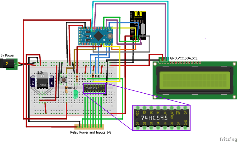
Hi All,
Does anyone have a schematic/wiring diagram for this (especially the shift register)?
I may be too old, but the Fritzing image on the build page isn't clear to me.
-
@dbemowsk Thanks, that clears it up.
I ended up going with a Mega with LCD Shield and used additional digital pins for the relays. I wanted to enable the IRQ buffering for the NRF radio and some LCDText devices to report back to Vera some status information. Sadly I had to use Strings as I struggled to get char[] arrays to work. Got a bit hard to fit onto the memory of the Pro Mini.
I needed 2 controllers for front and back, one with Master Valve setup. The back reticulation is an extension of front zone - so Vera makes sure the front controller supplies water when the back controller is active.

If there's interest I'll post the code, maybe someone with better skills than me could rewrite the String section - I don't know if I'll have issues with memory fragmentation yet. Only installed them today.
A big thank you to @petewill and @BulldogLowell for sharing their code and design.
-
@dbemowsk Thanks, that clears it up.
I ended up going with a Mega with LCD Shield and used additional digital pins for the relays. I wanted to enable the IRQ buffering for the NRF radio and some LCDText devices to report back to Vera some status information. Sadly I had to use Strings as I struggled to get char[] arrays to work. Got a bit hard to fit onto the memory of the Pro Mini.
I needed 2 controllers for front and back, one with Master Valve setup. The back reticulation is an extension of front zone - so Vera makes sure the front controller supplies water when the back controller is active.
If there's interest I'll post the code, maybe someone with better skills than me could rewrite the String section - I don't know if I'll have issues with memory fragmentation yet. Only installed them today.
A big thank you to @petewill and @BulldogLowell for sharing their code and design.
-
@Spanners So you are saying that you just used digital IO lines instead of using the shift register? BTW, I like the case, looks expensive. Do you use the 5 keys on the keypad shield for anything?
@dbemowsk yep, I left out the shift register and just used additional IO pins.
The case was AU$28 at a local electronics supplier, or AU$10 from ebay. IP66 rated, should keep the Arduino's safe from the elements.
The LCD keypad has a reset button (handy for reloading all valve changes) and a select button which I'm using to do the same thing as the external button in the original design (I still have the exterior button as well). The other buttons could be used for a local menu system or for dialling in a custom manual run time or something, but I haven't pursued it as I don't intend to physically touch them very often. :)
I've got a problem that'd developed with the front controller - almost like the button/interrupt is triggering whenever the relays are energised/de-energised. It's not consistent though and I'm betting its power related.
The whole unit is powered by a 12VDC adaptor. The relays are powered by a separate DC-DC 5V supply off that 12V, and the Mega takes 12V on VIN and powers the LCD and the radio.
-
Ok, found my issue - hopefully you guys can give me a suggestion on how to fix it.
It basically is the external button being triggered (immediate irrigation halt or starts running all zones after shutdown). And it's caused by the 24VAC power running through the relays.
If I shut down the 24VAC power it works great. If I unplug the external button (brown wire in picture just above the LED), I have no issues either.
I'm not using an external resistor for that switch (PIN 21 to GND) - do you think that would solve the issue with interference from the 24VAC? Or is there another solution to these types of issues?
  pinMode(waterButtonPin, INPUT_PULLUP);
  attachInterrupt(digitalPinToInterrupt(waterButtonPin), PushButton, LOW); //May need to change for your Arduino model
It seems a bit counterintuitive, because how would the 24VAC which is presumably creating a magnetic field and inductive current in brown wire result in it reading LOW?
@Spanners Do you in any way have one leg of the 24V supply connected to low voltage side? Possibly the ground?
@Spanners said in Irrigation Controller (up to 16 valves with Shift Registers):
If I shut down the 24VAC power it works great.
When you have the 24V connected, is it under any load? And, What does this brown wire connect?
-
@Spanners Do you in any way have one leg of the 24V supply connected to low voltage side? Possibly the ground?
@Spanners said in Irrigation Controller (up to 16 valves with Shift Registers):
If I shut down the 24VAC power it works great.
When you have the 24V connected, is it under any load? And, What does this brown wire connect?
The 24VAC is completely isolated - it connects to the relays to power solenoids only, common wire like @petewill shows in his video. The other connection for the 24VAC is to the common wire on the solenoids. There's no path from the 24VAC to the Arduino.
24VAC is only under load when a relay is active and powering a solenoid. It's when a relay opens or closes that the external button interrupt is triggered (about 80% of the time).
The brown wire is PIN 21 to the external button, the other side of the button is connected to GND. If that wire is disconnected, I don't see the issue - so it's like the start/stop of 24VAC current flow is creating enough magnetic action/induced current or something on the wire and PIN 21 to trigger the interrupt.
-
The 24VAC is completely isolated - it connects to the relays to power solenoids only, common wire like @petewill shows in his video. The other connection for the 24VAC is to the common wire on the solenoids. There's no path from the 24VAC to the Arduino.
24VAC is only under load when a relay is active and powering a solenoid. It's when a relay opens or closes that the external button interrupt is triggered (about 80% of the time).
The brown wire is PIN 21 to the external button, the other side of the button is connected to GND. If that wire is disconnected, I don't see the issue - so it's like the start/stop of 24VAC current flow is creating enough magnetic action/induced current or something on the wire and PIN 21 to trigger the interrupt.
@Spanners Does the arduino input for the switch (brown wire) have a pull up (or pull down depending on your use case) resistor on it? Something like this:
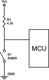
If the arduino input is left floating when the button is in an unpressed state, I suppose that induction could possibly cause enough fluctuation to cause it to trip that switch input. The arduino inputs are very sensitive and the brown wire may be acting like an antenna and picking up enough induced current from the 24v side to trip the input. The 24 volts used is typically AC which would affect something like that more than a DC voltage would, so when one of the relays turns on, then you have the AC current flowing which could easily be picked up by your brown wire (the antenna). When you disconnect the brown wire, there is no more antenna to sway the input. Read the first response to this guys question. Pull up/down resistors simply bias that input to a given state (high or low) when no expressed input is given (unpressed switch). -
@Spanners Does the arduino input for the switch (brown wire) have a pull up (or pull down depending on your use case) resistor on it? Something like this:
If the arduino input is left floating when the button is in an unpressed state, I suppose that induction could possibly cause enough fluctuation to cause it to trip that switch input. The arduino inputs are very sensitive and the brown wire may be acting like an antenna and picking up enough induced current from the 24v side to trip the input. The 24 volts used is typically AC which would affect something like that more than a DC voltage would, so when one of the relays turns on, then you have the AC current flowing which could easily be picked up by your brown wire (the antenna). When you disconnect the brown wire, there is no more antenna to sway the input. Read the first response to this guys question. Pull up/down resistors simply bias that input to a given state (high or low) when no expressed input is given (unpressed switch).@dbemowsk - you da man. Thanks for the help.
I was using the internal pull up on the Arduino and it wasn't enough to deal with the interference from the 24VAC. Added a 4.7k resistor to the switch with connection to Vcc as per your diagram and it's now working reliably.
Also needed to add a repeater node as the rear retic controller sits inside a garden feature that is made from 250mm thick limestone blocks. Comms were a little hit and miss.
Hello! It looks like you're interested in this conversation, but you don't have an account yet.
Getting fed up of having to scroll through the same posts each visit? When you register for an account, you'll always come back to exactly where you were before, and choose to be notified of new replies (either via email, or push notification). You'll also be able to save bookmarks and upvote posts to show your appreciation to other community members.
With your input, this post could be even better 💗
Register Login