Skip to content
  • MySensors
  • OpenHardware.io
  • Categories
  • Recent
  • Tags
  • Popular
Skins
  • Light
  • Brite
  • Cerulean
  • Cosmo
  • Flatly
  • Journal
  • Litera
  • Lumen
  • Lux
  • Materia
  • Minty
  • Morph
  • Pulse
  • Sandstone
  • Simplex
  • Sketchy
  • Spacelab
  • United
  • Yeti
  • Zephyr
  • Dark
  • Cyborg
  • Darkly
  • Quartz
  • Slate
  • Solar
  • Superhero
  • Vapor

  • Default (No Skin)
  • No Skin
Collapse
Brand Logo
  1. Home
  2. Hardware
  3. 110v-230v AC to Mysensors PCB board

110v-230v AC to Mysensors PCB board

Scheduled Pinned Locked Moved Hardware
269 Posts 63 Posters 270.9k Views 68 Watching
  • Oldest to Newest
  • Newest to Oldest
  • Most Votes
Reply
  • Reply as topic
Log in to reply
This topic has been deleted. Only users with topic management privileges can see it.
  • korttomaK Offline
    korttomaK Offline
    korttoma
    Hero Member
    wrote on last edited by
    #118

    there is no fuse on the relay switch so I guess either the PCB or the relay will fail.

    • Tomas
    1 Reply Last reply
    0
    • m26872M Offline
      m26872M Offline
      m26872
      Hardware Contributor
      wrote on last edited by
      #119

      I've seen commercial products with a thermal fuse glued to the switching side of the relay. Maybe that would help some in such situation.

      1 Reply Last reply
      0
      • korttomaK korttoma

        Whould a 5.1V zener work?

        edit: removed the link to the product so that no one would buy it the specs of it is to tight to be used with HLK.

        m26872M Offline
        m26872M Offline
        m26872
        Hardware Contributor
        wrote on last edited by m26872
        #120

        @korttoma A 5.1V zener is probably too tight. The HLK seems rated 5+/-0.2V.

        bjornhallbergB 1 Reply Last reply
        0
        • m26872M m26872

          @korttoma A 5.1V zener is probably too tight. The HLK seems rated 5+/-0.2V.

          bjornhallbergB Offline
          bjornhallbergB Offline
          bjornhallberg
          Hero Member
          wrote on last edited by
          #121

          @m26872 Indeed, mine is 5.08V (with no load). I ordered some 5.1V and 5.6V 1206 SMD diodes from Ali for future use. Plus some 3.6V. And a set of DIP diodes.

          rvendrameR 1 Reply Last reply
          0
          • bjornhallbergB bjornhallberg

            @m26872 Indeed, mine is 5.08V (with no load). I ordered some 5.1V and 5.6V 1206 SMD diodes from Ali for future use. Plus some 3.6V. And a set of DIP diodes.

            rvendrameR Offline
            rvendrameR Offline
            rvendrame
            Hero Member
            wrote on last edited by
            #122

            @bjornhallberg said:

            I ordered some 5.1V and 5.6V 1206 SMD diodes

            Just to remember, the typical zeners are 1W , which gives a max of 200mA of output capacity, pretty enough for Arduino+radio, but maybe not enough for many relays / Leds etc. And if they burn due overload, they will allow all voltage/current flowing from PSU into arduino.

            That explains why we suggested the varistor, in order to short the PSU output and trigger its internal protection. Strange that your varistors didn't survive... Bad lot? Maybe they are not 5.5V as stated?

            Home Assistant / Vera Plus UI7
            ESP8266 GW + mySensors 2.3.2
            Alexa / Google Home

            m26872M 1 Reply Last reply
            0
            • rvendrameR rvendrame

              @bjornhallberg said:

              I ordered some 5.1V and 5.6V 1206 SMD diodes

              Just to remember, the typical zeners are 1W , which gives a max of 200mA of output capacity, pretty enough for Arduino+radio, but maybe not enough for many relays / Leds etc. And if they burn due overload, they will allow all voltage/current flowing from PSU into arduino.

              That explains why we suggested the varistor, in order to short the PSU output and trigger its internal protection. Strange that your varistors didn't survive... Bad lot? Maybe they are not 5.5V as stated?

              m26872M Offline
              m26872M Offline
              m26872
              Hardware Contributor
              wrote on last edited by
              #123

              @rvendrame
              No.
              The zener will only lead current during over voltage condition and only needs to dissapate enough energy till one of your (multiple?) over current protection trips. Just as your varistor setup is supposed to work.

              rvendrameR 1 Reply Last reply
              0
              • m26872M m26872

                @rvendrame
                No.
                The zener will only lead current during over voltage condition and only needs to dissapate enough energy till one of your (multiple?) over current protection trips. Just as your varistor setup is supposed to work.

                rvendrameR Offline
                rvendrameR Offline
                rvendrame
                Hero Member
                wrote on last edited by
                #124

                @m26872 , is it also true in case the PSU itself fail? And what happens if the circuit consumes more current than zener rating? I'm my (poor) knowledge, zeners are more relevant for stabilization, while varistor are effective 'protection' devices...

                Home Assistant / Vera Plus UI7
                ESP8266 GW + mySensors 2.3.2
                Alexa / Google Home

                m26872M 1 Reply Last reply
                0
                • M mvdarend

                  I spoke too soon... the unit seems to work well, but I hadn't tested if the relay actually switched or not. The status seems to change fine in the serial monitor, but it doesn't seem to be actually switching. I'll have to do some more troubleshooting.

                  S Offline
                  S Offline
                  shabba
                  wrote on last edited by
                  #125

                  @mvdarend You discover your issue with the relay?

                  M 1 Reply Last reply
                  0
                  • rvendrameR rvendrame

                    @m26872 , is it also true in case the PSU itself fail? And what happens if the circuit consumes more current than zener rating? I'm my (poor) knowledge, zeners are more relevant for stabilization, while varistor are effective 'protection' devices...

                    m26872M Offline
                    m26872M Offline
                    m26872
                    Hardware Contributor
                    wrote on last edited by
                    #126

                    @rvendrame
                    since we're discussing the PSU secondary side (output side), I think we already presume errors with the PSU. A fuse (over current protection) on the secondary is not just there as a back-up if the PSU internal over current protection fails. The fuse will also prevent your over voltage protection (zener, varistor, ...) from overload/burn/start a fire.

                    The current from PSU to load will not pass through the zener and hence the rating is irrelevant from that perspective. In other applications where a zener is used as voltage regulator, the full load current will pass through the zener when in idleing and then the rating is critical.

                    korttomaK 1 Reply Last reply
                    0
                    • m26872M m26872

                      @rvendrame
                      since we're discussing the PSU secondary side (output side), I think we already presume errors with the PSU. A fuse (over current protection) on the secondary is not just there as a back-up if the PSU internal over current protection fails. The fuse will also prevent your over voltage protection (zener, varistor, ...) from overload/burn/start a fire.

                      The current from PSU to load will not pass through the zener and hence the rating is irrelevant from that perspective. In other applications where a zener is used as voltage regulator, the full load current will pass through the zener when in idleing and then the rating is critical.

                      korttomaK Offline
                      korttomaK Offline
                      korttoma
                      Hero Member
                      wrote on last edited by
                      #127

                      @m26872 so how do we need to rate the zener? Should the zener be rated so that the fuse will blow before the zener brakes from the current it passes due to an over voltage situation? Or is it OK that the zener brakes to as long as it takes out the fuse first. Then an automatic fuse will no longer work.

                      • Tomas
                      m26872M 1 Reply Last reply
                      0
                      • S shabba

                        @mvdarend You discover your issue with the relay?

                        M Offline
                        M Offline
                        mvdarend
                        wrote on last edited by
                        #128

                        @shabba said:

                        @mvdarend You discover your issue with the relay?

                        Sorry, since that post I tried a few small things. But then I got caught up in other projects/work/family :) and haven't had time time to look into it further.

                        1 Reply Last reply
                        0
                        • korttomaK korttoma

                          @m26872 so how do we need to rate the zener? Should the zener be rated so that the fuse will blow before the zener brakes from the current it passes due to an over voltage situation? Or is it OK that the zener brakes to as long as it takes out the fuse first. Then an automatic fuse will no longer work.

                          m26872M Offline
                          m26872M Offline
                          m26872
                          Hardware Contributor
                          wrote on last edited by m26872
                          #129

                          @korttoma Good questions. As always a trade-off of risk, cost, space, taste, etc. They should already be answered in the varistor case though. Personally I think it's overkill with additional overvoltage protection at the low volt secondary side of a good quality PSU and an inexpensive load - fuse, capacitors and regulators should be more than enough. Focus should be the primary side protections.

                          Edit: Btw. Found some reading. See p.44

                          1 Reply Last reply
                          0
                          • bjornhallbergB Offline
                            bjornhallbergB Offline
                            bjornhallberg
                            Hero Member
                            wrote on last edited by
                            #130

                            Just a quick post to confirm I got the relays working as well (with Domoticz). I didn't read the schematic at first and just assumed how the mains and relay external wiring should be done. Still no idea about the smoking varistor.

                            S 1 Reply Last reply
                            0
                            • bjornhallbergB bjornhallberg

                              Just a quick post to confirm I got the relays working as well (with Domoticz). I didn't read the schematic at first and just assumed how the mains and relay external wiring should be done. Still no idea about the smoking varistor.

                              S Offline
                              S Offline
                              shabba
                              wrote on last edited by
                              #131

                              I thought all my relays were shot as I was not getting continuity on the load pins when I applied 5V. I checked resistance and there is just over 2K when 5V applied and infinite when none. I am going to put back together assuming the 240V A/C will pass through just fine.

                              1 Reply Last reply
                              0
                              • S Offline
                                S Offline
                                shabba
                                wrote on last edited by
                                #132

                                What would cause no power to VCC when connected to mains (even though there is 5V at end of HLK-PM01) - if I bring that 5V with a jumper to VCC it works. Also works fine when connected to the serial port - Bad DC varistor?

                                1 Reply Last reply
                                0
                                • korttomaK Offline
                                  korttomaK Offline
                                  korttoma
                                  Hero Member
                                  wrote on last edited by korttoma
                                  #133

                                  @shabba

                                  The only thing between the HLK-PM01 and VCC is Fuse2. Check the Schematic. But yes a shorted varistor will in the combination with the fuse bring VCC to 0V. I experienced this also since the 5.5V varistors I bought from the link in the documentation (Ali seller Unionup Electronic Mall) did not work.

                                  Seems like there is quite many of us that are having problems with the 5.5V varistors. I measured a few from my batch and they all show 0.4ohm with a multimeter, should they not have something like infinite resistance unless they get more then the 5.5V? My multimeter gives 0.6V when it measures resistance.

                                  • Tomas
                                  RJ_MakeR 1 Reply Last reply
                                  0
                                  • korttomaK korttoma

                                    @shabba

                                    The only thing between the HLK-PM01 and VCC is Fuse2. Check the Schematic. But yes a shorted varistor will in the combination with the fuse bring VCC to 0V. I experienced this also since the 5.5V varistors I bought from the link in the documentation (Ali seller Unionup Electronic Mall) did not work.

                                    Seems like there is quite many of us that are having problems with the 5.5V varistors. I measured a few from my batch and they all show 0.4ohm with a multimeter, should they not have something like infinite resistance unless they get more then the 5.5V? My multimeter gives 0.6V when it measures resistance.

                                    RJ_MakeR Offline
                                    RJ_MakeR Offline
                                    RJ_Make
                                    Hero Member
                                    wrote on last edited by
                                    #134

                                    @korttoma Say what...? You measure .4 ohms on your Varistor? I think you found your problem. :angry:

                                    I have only ever used Varistor protection on the primary side, so I've got no experience with low voltage Varistors, but I don't think it should ever read .4.. Should be infinite.

                                    RJ_Make

                                    korttomaK 1 Reply Last reply
                                    0
                                    • BSoftB Offline
                                      BSoftB Offline
                                      BSoft
                                      wrote on last edited by BSoft
                                      #135

                                      Hello everyone,

                                      Since we probably wanting this for multiple destinations, what if we used a centralized way at our home powerswitch.

                                      We could stack multiple boards, and just use one arduino nano and one nRF on top of it. We just have to care about link each stack to a different arduino output.

                                      Based in this idea we could create a second pcb for stack mounting, this board will just have the SSR and a deep switch for easy selectable arduino output. To make this ok we should connect each home powerswitch to each stack, another way exist if we use the main supply of the bottom board for all stacks, and place our circuit before our home power switch, but this is not recommendable.

                                      For minimum stack size SSR should be horizontal mounted.

                                      The advantages are obvious, just one arduino and nRF, one ac-dc and regulator for all home switches. Super low volume occupied and no more size constraints inside wall switches.

                                      I don't have time to go forward and design this, so if someone wants it please go for it!! :smiley:

                                      PS - Since we just use one arduino output per stack, we could avoid deep switch cost and configure by soldering selected track.

                                      1 Reply Last reply
                                      0
                                      • sundberg84S Offline
                                        sundberg84S Offline
                                        sundberg84
                                        Hardware Contributor
                                        wrote on last edited by sundberg84
                                        #136

                                        @BSoft I had this idea also and have been working on a pcb for some weeks now.
                                        Its a 5x5 cm PCB you cut in halv so you get a 2 pcs which are 2.5x5cm - and they are stackable (like a shield).
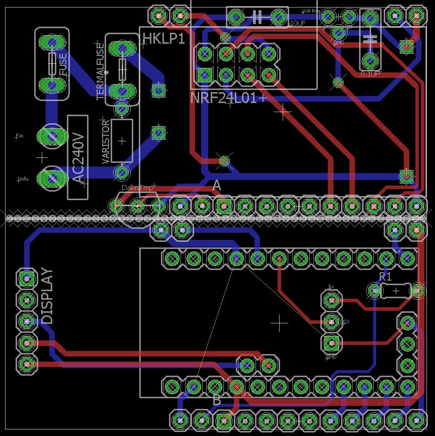
                                        1.JPG

                                        This is how i plan to stack them: (Blue inwall socket behind).
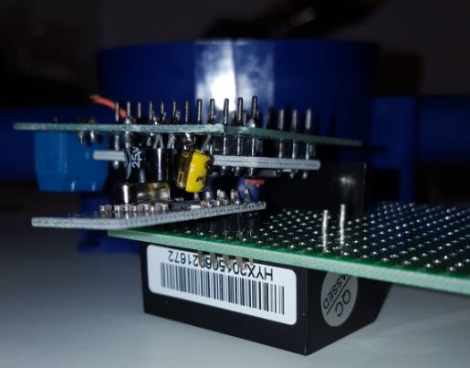
                                        2.JPG

                                        On the bottom you have the high power and HK 240->5v converter.
                                        Then in the middle between the pcbs you have the radio and arduino and on top whatever you wants.
                                        I have made outputs for LCD screen, buttons and/or motion.

                                        There are still much work in progress here but so far this is my thoughts... and it fits inside the typical wall hole.
                                        This will not be ready for atleast some week, and the three weeks or so with order/deliver time.

                                        I will create my own post to get input on this when im done and If someone else knows and want to improve the design i can send over the files.

                                        Controller: Proxmox VM - Home Assistant
                                        MySensors GW: Arduino Uno - W5100 Ethernet, Gw Shield Nrf24l01+ 2,4Ghz
                                        MySensors GW: Arduino Uno - Gw Shield RFM69, 433mhz
                                        RFLink GW - Arduino Mega + RFLink Shield, 433mhz

                                        1 Reply Last reply
                                        2
                                        • BSoftB Offline
                                          BSoftB Offline
                                          BSoft
                                          wrote on last edited by BSoft
                                          #137

                                          @sundberg84 Nice work with that sandwich!! :stuck_out_tongue:
                                          Maybe you could move nrf24 to the other board to get away from ac-dc field and obtain better signal exposure.

                                          My idea is to move this node to my home powerswitch and control all my home lights, but as size isn't a problem maybe i'll use this:
                                          http://www.dx.com/p/8-channel-5v-solid-state-relay-module-blue-black-green-250v-2a-213880

                                          1 Reply Last reply
                                          0
                                          Reply
                                          • Reply as topic
                                          Log in to reply
                                          • Oldest to Newest
                                          • Newest to Oldest
                                          • Most Votes


                                          17

                                          Online

                                          11.7k

                                          Users

                                          11.2k

                                          Topics

                                          113.0k

                                          Posts


                                          Copyright 2019 TBD   |   Forum Guidelines   |   Privacy Policy   |   Terms of Service
                                          • Login

                                          • Don't have an account? Register

                                          • Login or register to search.
                                          • First post
                                            Last post
                                          0
                                          • MySensors
                                          • OpenHardware.io
                                          • Categories
                                          • Recent
                                          • Tags
                                          • Popular