110v-230v AC to Mysensors PCB board
-
@TD22057 said:
@petewill said:
I don't remember where I read this but it was advised not to use resettable fuses with the HLK. Basically it was said that if the fuse were to blow the HLK would have already been stressed to the point where it may be unsafe and it's best to replace the whole device. I wish I could remember where I read that but I'm not sure...
I'm 90% certain that was from the guy who did the power tests of the HLK. I believe he was saying that these small PSU's don't handle heat or spikes well and if the fuse goes, you should assume the PSU is unsafe as well and replace it.
Here it is I guess: http://lygte-info.dk/review/Power Mains to 5V 0.6A Hi-Link HLK-PM01 UK.html
Quote: "I would place a fuse or fusible resistor before the converter, the fuse is not supposed to be replaceable, when it blows it is time to replace the converter."
@HenryWhite it mean that appart if you make a direct shortcut with a metal part, the only thing that came make the fuse blow, it is because of the HLK part.
So: fuse blow = HLK dead.
HLK dead = you don't need a resettable fuse, as you have to unsolder the HLK to repair the board (if no component seam to be dead after this one). -
Hi and thanks for sharing your project!!! I'm new here and up to now I've been using Fritzing as PCB design tool. I'm impressed with the 3D preview of diptrace. I've imported your project since is almost what I need, but I need some changes: ESP8266 (E-12/E-04) instead or Arduino and Relay instead of SSR.
When I import your project I can't see 3D preview of HLK. How do I import this 3D part? Where's can I find the Songle Relay part that has been shown above?
Just one more question: why do you use NRF24L01 + Arduino if you can do the same and more with ESP8266?? :o/
Thanks again and best regads!!!
P.S.
I'll share my PCB if you wish.
-
Hi all,
**UPDATE April 17 2016 **
The latest version of this board is available HERE.After spending a few months on this forum and a few prototypes later, I decided I wanted to build a small but cheap PCB which could be placed in either the wall behind the light switch, or above the lamp.
Besides the boards I've seen on this forum, I wanted these boards to contain a module to go from 230v AC to 5/3.3v DC in order to power an Arduino nano and the NRF module. I eventually ended up with a PCB which is about 4 by 4.5cm. So with all components attached I'm hoping to get in stuffed in a 5x5x3cm plastic printed case.
Modules which I've used to power the board:
[http://www.aliexpress.com/item/5-pcs-HLK-PM01-AC-DC-220V-to-5V-Step-Down-Power-Supply-Module-Intelligent-Household/32319202093.html?spm=2114.32010308.4.19.8oKfZgUPDATE: 2015/09/18
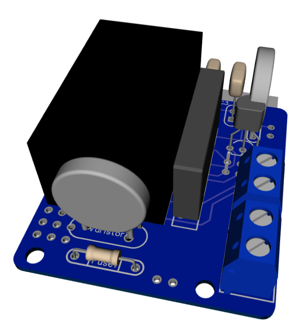
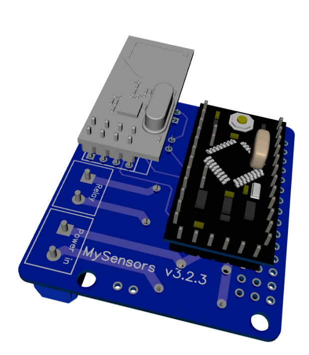
As promised, I've got an update for this project. The board has been tested in the past week, and everything is working as expected. Compared to the previous board I've posted, I have updated the following:
• Solder pads of LE33CZ have been placed a little wider apart to avoid short circuit while soldering.
• Solder pads of the resettable fuse (Fuse2) has been placed closer together to better fit the fuses of the BOM.
• Moved the NRF24L01 connector a bit away from the solid state relay. Should make it easier to solder.
• Moved Fuse2 to another location on the board, away from the 230v circuit.Some 3D pictures (Top and bottom):
Anyone who is interested can order the PCB HERE
Some documentation, complete list of required components and all gerber / DipTrace files (in case you would like to make some modifications) can be found here: MySensors board v3.2.3.zip.
@aproxx said:
Hi all,
After spending a few months on this forum and a few prototypes later, I decided I wanted to build a small but cheap PCB which could be placed in either the wall behind the light switch, or above the lamp.
Besides the boards I've seen on this forum, I wanted these boards to contain a module to go from 230v AC to 5/3.3v DC in order to power an Arduino nano and the NRF module. I eventually ended up with a PCB which is about 4 by 4.5cm. So with all components attached I'm hoping to get in stuffed in a 5x5x3cm plastic printed case.
Modules which I've used to power the board:
[http://www.aliexpress.com/item/5-pcs-HLK-PM01-AC-DC-220V-to-5V-Step-Down-Power-Supply-Module-Intelligent-Household/32319202093.html?spm=2114.32010308.4.19.8oKfZgUPDATE: 2015/09/18
As promised, I've got an update for this project. The board has been tested in the past week, and everything is working as expected. Compared to the previous board I've posted, I have updated the following:
• Solder pads of LE33CZ have been placed a little wider apart to avoid short circuit while soldering.
• Solder pads of the resettable fuse (Fuse2) has been placed closer together to better fit the fuses of the BOM.
• Moved the NRF24L01 connector a bit away from the solid state relay. Should make it easier to solder.
• Moved Fuse2 to another location on the board, away from the 230v circuit.Some 3D pictures (Top and bottom):
Anyone who is interested can order the PCB HERE
Some documentation, complete list of required components and all gerber / DipTrace files (in case you would like to make some modifications) can be found here: MySensors board v3.2.3.zip.
-
Just ordered 10 pcs of this board. Great Job!
-
HLK spec. is max input of 0.2a with small spikes tolerance to 1.0A. I also ran out of 0.3 but are now using 0.2a and that works fine.
-
Does the light switch need to be a SPST or can you use a pushbutton? Curious how this would work with a SPST switch. I haven't looked at the code to see what is setup.
-
-
Hey Guys,
I am working on ESP8266 as well. But I am newbie to electronic designs. But in my view it should be silmple and we can replace Arduino nano with ESP8266 and remove NRF module.One diagram and circuit is explained here http://iot-playground.com/blog/2-uncategorised/77-esp8266-internet-controlled-switch-easyiot-cloud-mqtt-api#materials
@csa02221862 you can use this cercuit with SPST buttons. But Switch will notbe connected to mains. It will be conneted to ESP8266 GPIO of (or arduino). And in Sketch (i.e code ) you have to write code based on GPIO when ever it goes 0 to 1 or 1 to 0 Relay state shoud be toggled.
I hope I make sense
@aproxx you did great job here.
I am looking to reduce its size more if possible and wish to use ESP8266. Also looking to add more then one relays to the board. In some rooms there are 3 buttons on one panel. So thinking to use 3 relays. Will it be a good Idea? I think should not matter as long as I have enough GPIO to control relays and Electric wire connectors can bear the load.
-
Found something interesting on Aliexpress which is a drop in replacement for the HLK-PM01:
the HLK-PM03
Same size and pin locations, but 110-200 V AC to 3V3 DC.
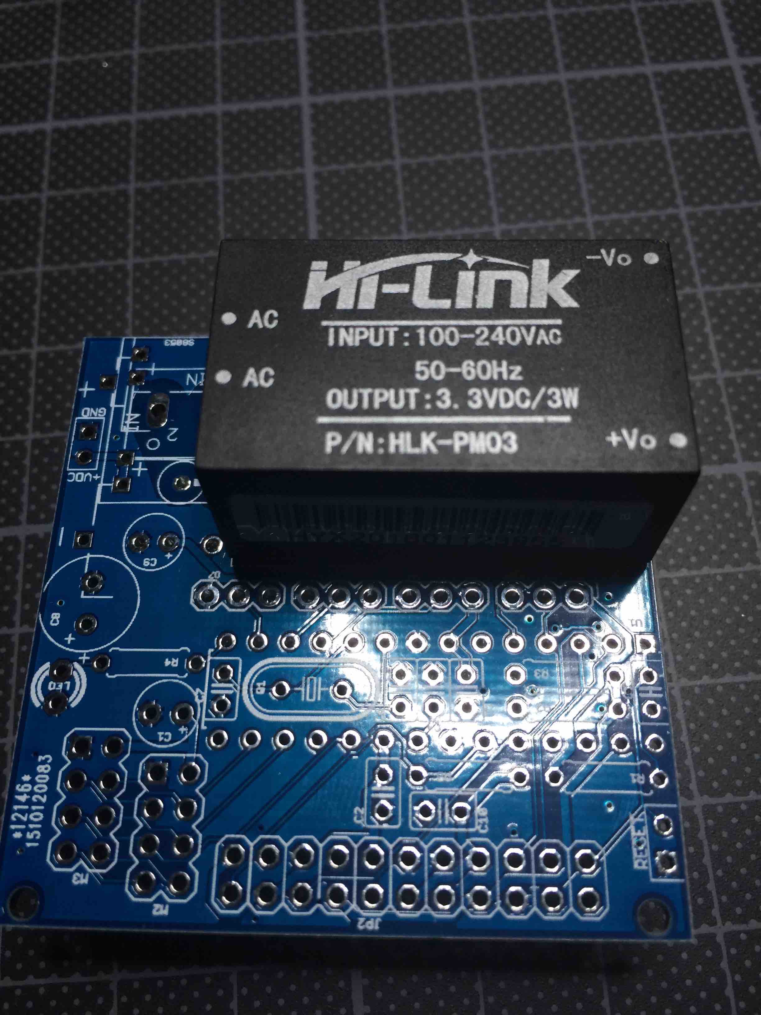
It fits my multi-power options board perfectly.
-
Nice find GertSanders ... I am planning to use esp8266 which runs on 3.3 volt... best fit ..
If we use this we may have to drop few things from 5.5 board right?
Like no need of 5v - 3.3 converter
change relay to match 3.3v like this http://vod.ebay.com/vod/FetchOrderDetails?qu=1&itemid=401045943120&transid=522355020027&viewpaymentstatus=Anyexpert around? do we need to remove anythingelse (any capacitor?)
-
But 3.3v relay will not match the board. If we use 5.5v relay do we need to add something to circuit?
-
Hi,
Thank you for this pcb. In which program did you do the design? Do you think you can share an editable version of the design?
I would like to modify it to accept the Mean Well IRM-05-5 instead of the Hi-Link.
It is more expensive and bigger AC-DC circuit but since I hace some in my stash i would like to use them. -
Nice find GertSanders ... I am planning to use esp8266 which runs on 3.3 volt... best fit ..
If we use this we may have to drop few things from 5.5 board right?
Like no need of 5v - 3.3 converter
change relay to match 3.3v like this http://vod.ebay.com/vod/FetchOrderDetails?qu=1&itemid=401045943120&transid=522355020027&viewpaymentstatus=Anyexpert around? do we need to remove anythingelse (any capacitor?)
@toabhishekverma said:
change relay to match 3.3v like this http://vod.ebay.com/vod/FetchOrderDetails?qu=1&itemid=401045943120&transid=522355020027&viewpaymentstatus=
That's a link to your shopping cart, we don't have access to...
I'm interested in the relay, can you post a working link? -
-
I use the same SONGLE relays:
http://www.aliexpress.com/item/5pcs-SRD-03VDC-SL-C-3V-relay-5-feet-10A/32453591000.html
-
@GertSanders thanks for this link.
So do you have working prototype? what board are you using? I am in middle of finalising components and trying to finalise design. With little knowledge of electronics my progress is slow.
Also for 220 to 3.3v there is another converter from Olimex https://www.olimex.com/Products/Power/PWR-90-240V-3.3V0.8A/
overall its abit smaller then Hi-Link... Hi-Link abit better because all covered and less dangerous.Please share if you have any design finalised.