110v-230v AC to Mysensors PCB board
-
I received the newly designed PCB last weekend, and have been soldering/testing the board since it arrived. Just a few minor changes to the layout (not the schematic) and the board should be completely finished! So far the results look promising.
@jemish: I'm currently re-working the design a bit and working on documentation, but I'll make sure to post the new and completely finished design by the end of the week! -
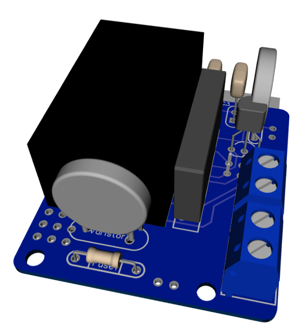
As promised, I've got an update for this project. The board has been tested in the past week, and everything is working as expected. Compared to the previous board I've posted, I have updated the following:
• Solder pads of LE33CZ have been placed a little wider apart to avoid short circuit while soldering.
• Solder pads of the resettable fuse (Fuse2) has been placed closer together to better fit the fuses of the BOM.
• Moved the NRF24L01 connector a bit away from the solid state relay. Should make it easier to solder.
• Moved Fuse2 to another location on the board, away from the 230v circuit.Some 3D pictures (Top and bottom):
Anyone who is interested can order the PCB HERE
Some documentation, and all gerber / DipTrace files (in case you would like to make some modifications) can be found here: MySensors board v3.2.3.zip.
-
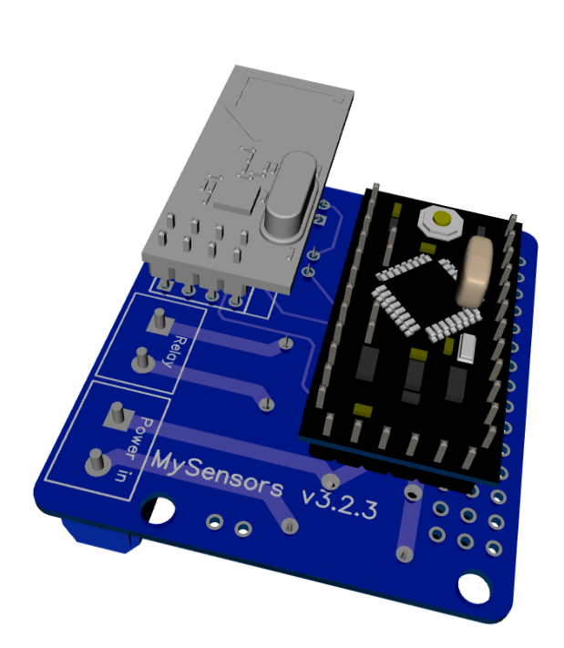
@aproxx I guess you use a different Arduino Pro Mini as the one in the 3D view, because its row of pins pointing towards us seems to get awfully close to the mains coming from "Power in", right?
@Yveaux
I believe those are for the serial connection that usually are pointing up, or back for programing? It looks like they are just rendered as down in the 3D image? But I am curious how the clearance for the components on the other side (HLK) is when they are soldered, does it need some space off the board? -
As promised, I've got an update for this project. The board has been tested in the past week, and everything is working as expected. Compared to the previous board I've posted, I have updated the following:
• Solder pads of LE33CZ have been placed a little wider apart to avoid short circuit while soldering.
• Solder pads of the resettable fuse (Fuse2) has been placed closer together to better fit the fuses of the BOM.
• Moved the NRF24L01 connector a bit away from the solid state relay. Should make it easier to solder.
• Moved Fuse2 to another location on the board, away from the 230v circuit.Some 3D pictures (Top and bottom):
Anyone who is interested can order the PCB HERE
Some documentation, and all gerber / DipTrace files (in case you would like to make some modifications) can be found here: MySensors board v3.2.3.zip.
-
@aproxx I guess you use a different Arduino Pro Mini as the one in the 3D view, because its row of pins pointing towards us seems to get awfully close to the mains coming from "Power in", right?
@Yveaux: I'm using the standard Arduino Nano, but I agree that the 3D view looks a bit worrying. In real life it isn't needed to solder this row of pins to the Arduino, so it should be safe. So the assumption of @DrJeff is correct!
The only reason why these pins look connected to the board is because I couldn't find a 3D design of the Arduino nano without these 6 pins soldered. :)
But thanks for pointing this out, I'll add it to the documentation to make sure people aren't getting confused.@AWI: I'll try and see if I can take some decent pictures when I get home (in approximately 12 hours) and post them up here!
-
For those who wanted to see some pictures of the board:
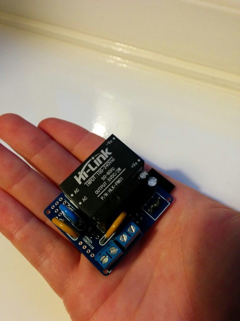
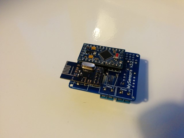
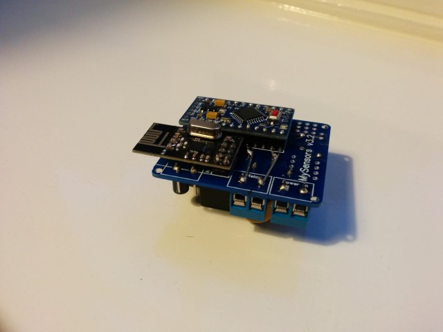
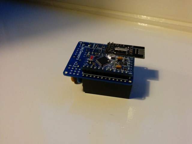
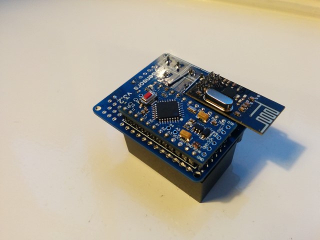
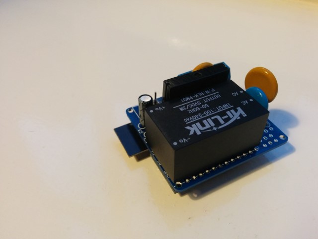
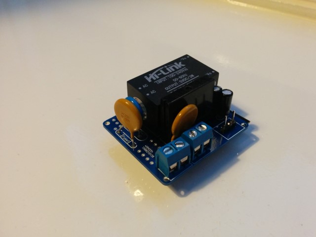
Small notice: These pictures are of a slightly older design. The newer design has a few minor changes like better component placement and a permanent fuse instead of this resettable fuse. But these pictures should at least give you an idea on how everything looks like, and shows how really small it actually is.
Also, I reinforced the traces of the 230v lines, which I absolutely recommend to do! (Although I do recommend to do it slightly more professional than I did on this prototype :)) -
For those who wanted to see some pictures of the board:
Small notice: These pictures are of a slightly older design. The newer design has a few minor changes like better component placement and a permanent fuse instead of this resettable fuse. But these pictures should at least give you an idea on how everything looks like, and shows how really small it actually is.
Also, I reinforced the traces of the 230v lines, which I absolutely recommend to do! (Although I do recommend to do it slightly more professional than I did on this prototype :)) -
@AWI Thanks for the kind words! I did my best on the soldering part, but the reinforcement of the 230v circuit could have done a bit better in my opinion. :) Next time I would use an isolated wire to reinforce the 230v traces, but for a prototype build this was sufficient.
-
Nice job. Why do you need to bridge the 230V lines? Can't you just make the traces bigger? Is it really needed? The relay can only switch 2A. So the traces have to survive 2A, too. You can easily calculate the required traces with tools like this: http://circuitcalculator.com/wordpress/2006/01/31/pcb-trace-width-calculator/
@Jan-Gatzke I've used a similar calculator before and according to these calculation it isn't mandatory.
- Dirtypcbs.com claims to use 1oz/ft2 copper thickness (which seems to be 0.035mm).
- The traces between the solid state relay and connectors are all 2mm wide.
- Distance between the solid state relay and the connector on the edge is less than 20mm.
That would lead to the following calculations:
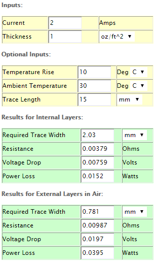
So you are right that it isn't mandatory to reinforce these traces. However, to be on the safe side I'm still planning to reinforce them. I know, it probably isn't necessary but it doesn't hurt putting this extra effort in, just to be completely safe. :)
-
Keep in mind, that you do not want to run the relay at 2A for a longer period of time. 2A at 230V means 460 W power consumption. Most devices / lights will consume less. So hopefully this will never be a problem.
Again, great job. I will definitely order some of the pcbs, too.
What about the other parts? Do you have some kind of link collection for Ebay/Ali? This would make it even easier to build the device.
@Jan-Gatzke Indeed, most of my lights only consume like 10% of the maximum rated power, so I should be on the safe side for sure.
I have attached a ZIP file which contains all required information in one of my previous posts (HERE). That one contains a Word document with all components and an AliExpress/Ebay link.
I'll try and see if I can update the first post of this topic as well to include all important information.
-
Ok, lazy me didn't have a look at the zip. Tanks for the hint. :)
-
@aproxx This looks very cool! I am curious what (if any) heat sink will be used with the solid state relay? I have never used a solid state relay but I have been reading about them and it seems that most are used with a heat sink. Maybe it depends on the amperage that will be switched though. Thanks!
-
The SSR has an integrated heat sink according to the specs. Don't know if this is a knockoff and follows the same standard of quality though. Given the low A rating, and the fact that most of us will be switching a 10-20W worth of lights, I think it will be fine.
I noticed the ceramic "Slow Blow Fuse (250v 0.3A)" was out of stock on Ebay. As was the 0.2A version. Someone is stocking up :-) Would it have to be a ceramic fuse?