Combined MySensor Gateway with 433Mhz transmitter (HomeEasy/Klik-Aan-Klik-uit)
-
In Holland there is an affordable popular brand for home automation called Klik-aan-klik-uit. These module are also sold in other countries as different brands like HomeEasy, more can be found here There are several (Aurdio) projects which decode en encode this RF protocol.
To be able to controll my HomeAutomation network with an Klik-aan-klik-uit (AYCT-104) remote controller i fitted my MySensor gateway with an RF 433Mhz receiver (and transmitter). The transmitter / receiver are of type : this type
I used the decoding software from (Randy Simons http://randysimons.nl/) which i modified so it can receive both the new
style and on style protocol messages. Read this thread for more background information.How to connect:
- Take a standard MySensors gateway
- And addtional connect the both the RF receiver and tansmitter ground and Vcc to the GND and 5V pins of your Ardiuno
- Connect the RF receiver data pin to Arduino pin 2 (interrupt 0 pin)
- Connect the RF transmitter data pin to Arduino pin 7
The recieved RC commands are sent to my Vera controller next to the MySensor messages. These commands have this format "rf;<number>" to be able to distinguish between MySensor commands and HomeEasy command i changed the MySensor lua-core file.
Other changes to the MySensor controller core are:
- Each received command is shown on the inclusion count area, the see which command can be used
- A scene controller is added on first inclusion, which can be use to activate scnenes where the scene number is the recieved command.
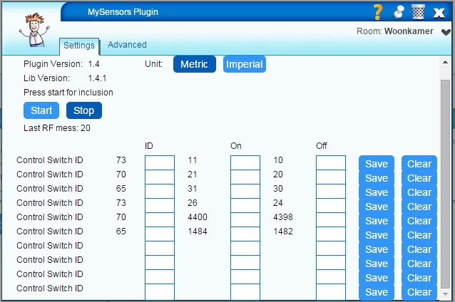
- The settings tab of primary MySensor device has a number of field where devices (Light) can be controlled directly on RF reception. The first column is the Vera device ID, the second column the RF code the switch on the device, the third column the RF code to switch off the column
The arduino code:
mySensorsRemoteGW.zipThe modified MySensors Vera code:
Vera_RFGateway.zip -
I do not have any experience with the Domoticz platform. But looking at the Domoticz's website, you either have to ask the developers to implement the RF message handling or do it yourselves (no rocket science), I could not find any plug in system.
It looks like coding and compiling.
For Vera i added and extra check in the MySensors message receiver, if the message starts with rf; i active the scene controller with number following the rf; tag. This is basic implementation which already suits a lot the possibilities
To have a more advanced solution i also extended the config interface for direct switching devices (with out the need for scene) and therefor a look up table is being checked at message reception. If you have a look in the Vera code i did mark all my changes in relation to the original code. Grts Bart
-
@treb0r this has been asked many times for different platforms in the domoticz forum.
They support some different gateways for 433mhz (Tellstick and mainly RFXCom) They dont want to decode all differente signals since its som many different brands. So as BartE said you have to code the RF message handling if you want to use another system.
Controller: Proxmox VM - Home Assistant
MySensors GW: Arduino Uno - W5100 Ethernet, Gw Shield Nrf24l01+ 2,4Ghz
MySensors GW: Arduino Uno - Gw Shield RFM69, 433mhz
RFLink GW - Arduino Mega + RFLink Shield, 433mhz -
@treb0r this has been asked many times for different platforms in the domoticz forum.
They support some different gateways for 433mhz (Tellstick and mainly RFXCom) They dont want to decode all differente signals since its som many different brands. So as BartE said you have to code the RF message handling if you want to use another system.
@sundberg84 ummmm assuming this all falls under one "virtual" mysensors device, it might be possible to map it in domotics into a virtual hardware. So, there is one mysensors device that is a gw, it spawns child devices as they appear. From now on it is sci-fi:
there will be a virtual hardware device (like the dummy device) that will get all the messages from the mysensors device and spawn new domoticz devices that will appear in the "devices" tab and will route all the messages to and from.
So, it seems possible but someone has to do it.... -
@Moshe-Livne Absolutely possible!! Say you have a MySensors 433mhz receiver device that listen and decode all incoming messages from your 433mhz devices you can send these through to Domoticz as different devices!
It doesnt have to be a dummy device, you can present all the devices to domoticz from your MySensors reciever as they are (Rain, Wind, Temp, Hum... if that is what you have in 433mhz sensors) Also some 433mhz sensors needs ack or code to know its talking to someone.
All i mean is that the dev. for domoticz doesnt want to do all the decoding since there is hardware (expensive) which already do this you can just connect. But if you have the knowledge its possible to do it yourself.
The same the other way around i think... but thats harder if you want to send... im not really sure there.
Controller: Proxmox VM - Home Assistant
MySensors GW: Arduino Uno - W5100 Ethernet, Gw Shield Nrf24l01+ 2,4Ghz
MySensors GW: Arduino Uno - Gw Shield RFM69, 433mhz
RFLink GW - Arduino Mega + RFLink Shield, 433mhz -
@Moshe-Livne Absolutely possible!! Say you have a MySensors 433mhz receiver device that listen and decode all incoming messages from your 433mhz devices you can send these through to Domoticz as different devices!
It doesnt have to be a dummy device, you can present all the devices to domoticz from your MySensors reciever as they are (Rain, Wind, Temp, Hum... if that is what you have in 433mhz sensors) Also some 433mhz sensors needs ack or code to know its talking to someone.
All i mean is that the dev. for domoticz doesnt want to do all the decoding since there is hardware (expensive) which already do this you can just connect. But if you have the knowledge its possible to do it yourself.
The same the other way around i think... but thats harder if you want to send... im not really sure there.
@sundberg84 if done through the "hardware" layer, sending back should work as well. but there is a lot of coding decoding.... that is for sure...
-
In Holland there is an affordable popular brand for home automation called Klik-aan-klik-uit. These module are also sold in other countries as different brands like HomeEasy, more can be found here There are several (Aurdio) projects which decode en encode this RF protocol.
To be able to controll my HomeAutomation network with an Klik-aan-klik-uit (AYCT-104) remote controller i fitted my MySensor gateway with an RF 433Mhz receiver (and transmitter). The transmitter / receiver are of type : this type
I used the decoding software from (Randy Simons http://randysimons.nl/) which i modified so it can receive both the new
style and on style protocol messages. Read this thread for more background information.How to connect:
- Take a standard MySensors gateway
- And addtional connect the both the RF receiver and tansmitter ground and Vcc to the GND and 5V pins of your Ardiuno
- Connect the RF receiver data pin to Arduino pin 2 (interrupt 0 pin)
- Connect the RF transmitter data pin to Arduino pin 7
The recieved RC commands are sent to my Vera controller next to the MySensor messages. These commands have this format "rf;<number>" to be able to distinguish between MySensor commands and HomeEasy command i changed the MySensor lua-core file.
Other changes to the MySensor controller core are:
- Each received command is shown on the inclusion count area, the see which command can be used
- A scene controller is added on first inclusion, which can be use to activate scnenes where the scene number is the recieved command.
- The settings tab of primary MySensor device has a number of field where devices (Light) can be controlled directly on RF reception. The first column is the Vera device ID, the second column the RF code the switch on the device, the third column the RF code to switch off the column
The arduino code:
mySensorsRemoteGW.zipThe modified MySensors Vera code:
Vera_RFGateway.zip -
I just programmed my second MySensors project. It's not so sophisticated as @BartE his gateway. But I made a sensor Node that act's as a 433Mhz Gateway for my cheap Impuls 433Mhz controlled outlets. The brand is Impuls and in Holland it's sold by a shop called Action, for around 10 or 15 euro's for 3 power outlets.
The Sketch acts as a gateway node for Domoticz and I'm able to turn on/off all my power outlets controlled by Domoticz. It was actualy easier than I thought, because there's a 433Mhz library for handling the Impuls protocol. I'm really amazed by how fast MySensors and Domoticz can communicate. It looks to me as if the lights go on/off at the same time I press the button in Domoticz. If someone is interested I'm happy to share the Sketch.
-
@TheoL said:
someone is interested I'm happy to share the Sketch.
sure please share.. does it work on the ethernet gateway?
i was looking at barte's code and it looks like it's only for serial@mvader Since it's just a Sensor it should work on any Gateway. After it's running you should see a new device in Domoticz with 5 sub nodes. They's all of the type lightning 2. Each sub device represents one of the swicthes on the impuls remote controller. The system code has to be adjusted to your own system code. On my outlets the dipswitches are all on, see the byte is 31.
 * MySensors node for switching on/of cheap 433Mhz based Power outlets from the Action
 * Author  Theo Leloux
 * Created 05-09-2015
 * Version 0.1alpha
 */

/**
 * Import the libraries needed by the Sketch
 */
#include <MySensor.h>
#include <SPI.h>
#include <RemoteTransmitter.h>

/**
 * Declare constants like pin settings etc.
 */
#define TRANSMITTERPIN 6 // documentation doesn't see anything if the needs to be a PWM, but why take the risk?
#define CHILD_ID_ACTION_SWITCH_A 1 // Declare the DEVICE A as a separate switch
#define CHILD_ID_ACTION_SWITCH_B 2 // Declare the DEVICE B as a separate switch -- In my situation I configured all outlet's as DEVICE A, so reserved for future useage
#define CHILD_ID_ACTION_SWITCH_C 3 // Declare the DEVICE B as a separate switch -- In my situation I configured all outlet's as DEVICE A, so reserved for future useage
#define CHILD_ID_ACTION_SWITCH_D 4 // Declare the DEVICE B as a separate switch -- In my situation I configured all outlet's as DEVICE A, so reserved for future useage
#define CHILD_ID_ACTION_SWITCH_E 5 // Declare the DEVICE B as a separate switch -- In my situation I configured all outlet's as DEVICE A, so reserved for future useage
const char SYSTEMCODE = char(31); // cast the integer byte value to a char should do the trick. Adjust this to your own SYSTEMCODE see RemoteTransmitter.h

/*
 * Declare variables
 */
ActionTransmitter switchTransmitter = ActionTransmitter( TRANSMITTERPIN );
unsigned long SLEEP_TIME = 5000; // the main loop will probably won't do a thing if we only attach a transmitter.
MySensor gw;

/*
 * Declare MySensors Messages
 */
MyMessage msgDeviceA( CHILD_ID_ACTION_SWITCH_A, V_LIGHT );
MyMessage msgDeviceB( CHILD_ID_ACTION_SWITCH_B, V_LIGHT );
MyMessage msgDeviceC( CHILD_ID_ACTION_SWITCH_C, V_LIGHT );
MyMessage msgDeviceD( CHILD_ID_ACTION_SWITCH_D, V_LIGHT );
MyMessage msgDeviceE( CHILD_ID_ACTION_SWITCH_E, V_LIGHT );

/**
 * Preparation code during initialization of the Arduino
 */
void setup() {
  // put your setup code here, to run once:
  // Serial.begin( 115200 );
  gw.begin( incomingMessage ); // attach a message handler for handling commands transmitted by the controller.

  gw.sendSketchInfo("433Mhz bridge", "1.0");       // Send the sketch version information to the gateway and Controller
  gw.present( CHILD_ID_ACTION_SWITCH_A, S_LIGHT ); // Present Device A to the gateway
  gw.present( CHILD_ID_ACTION_SWITCH_B, S_LIGHT ); // Present Device B to the gateway
  gw.present( CHILD_ID_ACTION_SWITCH_C, S_LIGHT ); // Present Device C to the gateway
  gw.present( CHILD_ID_ACTION_SWITCH_D, S_LIGHT ); // Present Device D to the gateway
  gw.present( CHILD_ID_ACTION_SWITCH_E, S_LIGHT ); // Present Device E to the gateway

  gw.sendBatteryLevel(100); // It just looks better in Domoticz if we let Domoticz no we're running on 100% power.

}

/**
 * The Sketch's main loop.
 */
void loop() {
  // I have nothing to do if only attach a transmitter.
  gw.wait( SLEEP_TIME ); // call the wait routine, which will allow for incomming messages during the waiting
}

void incomingMessage(const MyMessage &message) {
  Serial.println("message");
  // We only expect one type of message from controller. But we better check anyway.
  if (message.type==V_LIGHT) {
    char device = 64 + message.sensor; // translate child id to device ID. A = 65 so if we take off one and add the received sensor ID we get the correct device
  //  Serial.println( "Command received for Device " + (String)device + " on id " + (String)message.sensor + " request to turn " + (message.getBool()?"on":"off") );
    if ( device >= 'A' && device <= 'E' ) { // Impuls/Action system only allows device 'A' to 'E'
      switchTransmitter.sendSignal(SYSTEMCODE, device, message.getBool() );
    }
  }
}
I attached the 433 Mhz data line to pin 6 of the arduino. Not sure if it needs PWM. But I just started an hour ago and haven't had the time yet to look that up. For around 15 euro I'm able to control all my cheap 433Mhz outlets with Domoticz. I feel like a little kid in a candy shop ;)
Next thing to do is to hook up the receiver. So that I can receive the commands from the remote controller and send them to Domoticz. Work in progress hope to finish it this evening. But the reciever library has no support for impuls, so it might take a while.
-
@mvader Since it's just a Sensor it should work on any Gateway. After it's running you should see a new device in Domoticz with 5 sub nodes. They's all of the type lightning 2. Each sub device represents one of the swicthes on the impuls remote controller. The system code has to be adjusted to your own system code. On my outlets the dipswitches are all on, see the byte is 31.
 * MySensors node for switching on/of cheap 433Mhz based Power outlets from the Action
 * Author  Theo Leloux
 * Created 05-09-2015
 * Version 0.1alpha
 */

/**
 * Import the libraries needed by the Sketch
 */
#include <MySensor.h>
#include <SPI.h>
#include <RemoteTransmitter.h>

/**
 * Declare constants like pin settings etc.
 */
#define TRANSMITTERPIN 6 // documentation doesn't see anything if the needs to be a PWM, but why take the risk?
#define CHILD_ID_ACTION_SWITCH_A 1 // Declare the DEVICE A as a separate switch
#define CHILD_ID_ACTION_SWITCH_B 2 // Declare the DEVICE B as a separate switch -- In my situation I configured all outlet's as DEVICE A, so reserved for future useage
#define CHILD_ID_ACTION_SWITCH_C 3 // Declare the DEVICE B as a separate switch -- In my situation I configured all outlet's as DEVICE A, so reserved for future useage
#define CHILD_ID_ACTION_SWITCH_D 4 // Declare the DEVICE B as a separate switch -- In my situation I configured all outlet's as DEVICE A, so reserved for future useage
#define CHILD_ID_ACTION_SWITCH_E 5 // Declare the DEVICE B as a separate switch -- In my situation I configured all outlet's as DEVICE A, so reserved for future useage
const char SYSTEMCODE = char(31); // cast the integer byte value to a char should do the trick. Adjust this to your own SYSTEMCODE see RemoteTransmitter.h

/*
 * Declare variables
 */
ActionTransmitter switchTransmitter = ActionTransmitter( TRANSMITTERPIN );
unsigned long SLEEP_TIME = 5000; // the main loop will probably won't do a thing if we only attach a transmitter.
MySensor gw;

/*
 * Declare MySensors Messages
 */
MyMessage msgDeviceA( CHILD_ID_ACTION_SWITCH_A, V_LIGHT );
MyMessage msgDeviceB( CHILD_ID_ACTION_SWITCH_B, V_LIGHT );
MyMessage msgDeviceC( CHILD_ID_ACTION_SWITCH_C, V_LIGHT );
MyMessage msgDeviceD( CHILD_ID_ACTION_SWITCH_D, V_LIGHT );
MyMessage msgDeviceE( CHILD_ID_ACTION_SWITCH_E, V_LIGHT );

/**
 * Preparation code during initialization of the Arduino
 */
void setup() {
  // put your setup code here, to run once:
  // Serial.begin( 115200 );
  gw.begin( incomingMessage ); // attach a message handler for handling commands transmitted by the controller.

  gw.sendSketchInfo("433Mhz bridge", "1.0");       // Send the sketch version information to the gateway and Controller
  gw.present( CHILD_ID_ACTION_SWITCH_A, S_LIGHT ); // Present Device A to the gateway
  gw.present( CHILD_ID_ACTION_SWITCH_B, S_LIGHT ); // Present Device B to the gateway
  gw.present( CHILD_ID_ACTION_SWITCH_C, S_LIGHT ); // Present Device C to the gateway
  gw.present( CHILD_ID_ACTION_SWITCH_D, S_LIGHT ); // Present Device D to the gateway
  gw.present( CHILD_ID_ACTION_SWITCH_E, S_LIGHT ); // Present Device E to the gateway

  gw.sendBatteryLevel(100); // It just looks better in Domoticz if we let Domoticz no we're running on 100% power.

}

/**
 * The Sketch's main loop.
 */
void loop() {
  // I have nothing to do if only attach a transmitter.
  gw.wait( SLEEP_TIME ); // call the wait routine, which will allow for incomming messages during the waiting
}

void incomingMessage(const MyMessage &message) {
  Serial.println("message");
  // We only expect one type of message from controller. But we better check anyway.
  if (message.type==V_LIGHT) {
    char device = 64 + message.sensor; // translate child id to device ID. A = 65 so if we take off one and add the received sensor ID we get the correct device
  //  Serial.println( "Command received for Device " + (String)device + " on id " + (String)message.sensor + " request to turn " + (message.getBool()?"on":"off") );
    if ( device >= 'A' && device <= 'E' ) { // Impuls/Action system only allows device 'A' to 'E'
      switchTransmitter.sendSignal(SYSTEMCODE, device, message.getBool() );
    }
  }
}
I attached the 433 Mhz data line to pin 6 of the arduino. Not sure if it needs PWM. But I just started an hour ago and haven't had the time yet to look that up. For around 15 euro I'm able to control all my cheap 433Mhz outlets with Domoticz. I feel like a little kid in a candy shop ;)
Next thing to do is to hook up the receiver. So that I can receive the commands from the remote controller and send them to Domoticz. Work in progress hope to finish it this evening. But the reciever library has no support for impuls, so it might take a while.
-
@TheoL so you put the 433mhz transmitter on a separate sensor?
the way that i was thinking the OP had done it and as i had thought of doing it
was to put the 433mhz transmitter on the gateway itself.
but i imagine it would work either way.@mvader Yes for me it's easier and actually the only way. My gateway is not located in my living room, but in the closet with my energy meter. 2.4 Ghz can reach my living room, but the 433Mhz just doesn't get there. So be adding a sensor node, which acts as a 5 switch controller I can control the power outlets. In my bedroom I have some other Impuls power outlets. So I'll just install another gateway or bridge there as well and I'll be done.
I'm having a hard time decoding the remote control commands. It should be an easy to decode bitpattern. But it's getting late. I'll try to solve this puzzle tomorrow.
-
@mvader Yes for me it's easier and actually the only way. My gateway is not located in my living room, but in the closet with my energy meter. 2.4 Ghz can reach my living room, but the 433Mhz just doesn't get there. So be adding a sensor node, which acts as a 5 switch controller I can control the power outlets. In my bedroom I have some other Impuls power outlets. So I'll just install another gateway or bridge there as well and I'll be done.
I'm having a hard time decoding the remote control commands. It should be an easy to decode bitpattern. But it's getting late. I'll try to solve this puzzle tomorrow.
@TheoL i'm not sure what hardware you are using.but i have the etekcity ZAP 433 remote & outlets.
i just bought a 433 mhz transceiver off ebay and hooked it up to my raspberry pi2 and sniffed the codes.
i found it easier than going the arduino route. however the whole intention was to run this off the mysensors network i'm building. so the RPI2 was just for sniffing the codes. -
@mvader Yes for me it's easier and actually the only way. My gateway is not located in my living room, but in the closet with my energy meter. 2.4 Ghz can reach my living room, but the 433Mhz just doesn't get there. So be adding a sensor node, which acts as a 5 switch controller I can control the power outlets. In my bedroom I have some other Impuls power outlets. So I'll just install another gateway or bridge there as well and I'll be done.
I'm having a hard time decoding the remote control commands. It should be an easy to decode bitpattern. But it's getting late. I'll try to solve this puzzle tomorrow.
-
RFLink and Domoticz work great together with klik aan klik uit and my Alecto WS 3500 weather station. Also receiving weather sensors from my neighbours. Next project is building Mysensors.org sensors. RFLink works alsoas an gateway.
-
@mvader I just hooked up a set of cheap 433mhz transmitter and receiver (see http://www.seeedstudio.com/depot/images/product/rf433k.jpg). I added a 20 cm wire as an antena to the transmitter. which worked out great. The transmitter on the arduino has a larger transmitting range than my remote control!
@AWI sniffing wasn't the problem. I received all commands send by my remote control, the impuls protocol should be really simpel. SYSTEMCODE (5 bits) device (5 bits) command (2 bits). But it seems like they use some kind of encoding mechanism, because the bit pattern I receive doesn't follow that pattern. I'll have to lookup how to decode trits (for whatever that may be)
@Bazeman RFlink looks really cool, thanks for the advice. But I think I'll try to get this to work somehow. I'm close to the solution, and I only need a bridge for my Impuls power outleds. As tempting as it is to use my neighbours weatherstation, I don't want to depend on him changing the batteries in time. I have a frost alarm that wakes me up earlier during wintertime, whenever I have to remove the ice from the windows of my car. For the moment I'm using the forecast IO services for measuring outside weather conditions.
Besides i'm a DIY kind of guy. I like to make and design things myself. I want to build the solar powered weather station comming winter. As of now I have to leave the 433mHz bridge as is. Because I'm having some guest whom will be staying with us for the next two weeks. They will sleep in the room in which I do my electronic stuff. I have to clean that up :(
-
@mvader Since it's just a Sensor it should work on any Gateway. After it's running you should see a new device in Domoticz with 5 sub nodes. They's all of the type lightning 2. Each sub device represents one of the swicthes on the impuls remote controller. The system code has to be adjusted to your own system code. On my outlets the dipswitches are all on, see the byte is 31.
 * MySensors node for switching on/of cheap 433Mhz based Power outlets from the Action
 * Author  Theo Leloux
 * Created 05-09-2015
 * Version 0.1alpha
 */

/**
 * Import the libraries needed by the Sketch
 */
#include <MySensor.h>
#include <SPI.h>
#include <RemoteTransmitter.h>

/**
 * Declare constants like pin settings etc.
 */
#define TRANSMITTERPIN 6 // documentation doesn't see anything if the needs to be a PWM, but why take the risk?
#define CHILD_ID_ACTION_SWITCH_A 1 // Declare the DEVICE A as a separate switch
#define CHILD_ID_ACTION_SWITCH_B 2 // Declare the DEVICE B as a separate switch -- In my situation I configured all outlet's as DEVICE A, so reserved for future useage
#define CHILD_ID_ACTION_SWITCH_C 3 // Declare the DEVICE B as a separate switch -- In my situation I configured all outlet's as DEVICE A, so reserved for future useage
#define CHILD_ID_ACTION_SWITCH_D 4 // Declare the DEVICE B as a separate switch -- In my situation I configured all outlet's as DEVICE A, so reserved for future useage
#define CHILD_ID_ACTION_SWITCH_E 5 // Declare the DEVICE B as a separate switch -- In my situation I configured all outlet's as DEVICE A, so reserved for future useage
const char SYSTEMCODE = char(31); // cast the integer byte value to a char should do the trick. Adjust this to your own SYSTEMCODE see RemoteTransmitter.h

/*
 * Declare variables
 */
ActionTransmitter switchTransmitter = ActionTransmitter( TRANSMITTERPIN );
unsigned long SLEEP_TIME = 5000; // the main loop will probably won't do a thing if we only attach a transmitter.
MySensor gw;

/*
 * Declare MySensors Messages
 */
MyMessage msgDeviceA( CHILD_ID_ACTION_SWITCH_A, V_LIGHT );
MyMessage msgDeviceB( CHILD_ID_ACTION_SWITCH_B, V_LIGHT );
MyMessage msgDeviceC( CHILD_ID_ACTION_SWITCH_C, V_LIGHT );
MyMessage msgDeviceD( CHILD_ID_ACTION_SWITCH_D, V_LIGHT );
MyMessage msgDeviceE( CHILD_ID_ACTION_SWITCH_E, V_LIGHT );

/**
 * Preparation code during initialization of the Arduino
 */
void setup() {
  // put your setup code here, to run once:
  // Serial.begin( 115200 );
  gw.begin( incomingMessage ); // attach a message handler for handling commands transmitted by the controller.

  gw.sendSketchInfo("433Mhz bridge", "1.0");       // Send the sketch version information to the gateway and Controller
  gw.present( CHILD_ID_ACTION_SWITCH_A, S_LIGHT ); // Present Device A to the gateway
  gw.present( CHILD_ID_ACTION_SWITCH_B, S_LIGHT ); // Present Device B to the gateway
  gw.present( CHILD_ID_ACTION_SWITCH_C, S_LIGHT ); // Present Device C to the gateway
  gw.present( CHILD_ID_ACTION_SWITCH_D, S_LIGHT ); // Present Device D to the gateway
  gw.present( CHILD_ID_ACTION_SWITCH_E, S_LIGHT ); // Present Device E to the gateway

  gw.sendBatteryLevel(100); // It just looks better in Domoticz if we let Domoticz no we're running on 100% power.

}

/**
 * The Sketch's main loop.
 */
void loop() {
  // I have nothing to do if only attach a transmitter.
  gw.wait( SLEEP_TIME ); // call the wait routine, which will allow for incomming messages during the waiting
}

void incomingMessage(const MyMessage &message) {
  Serial.println("message");
  // We only expect one type of message from controller. But we better check anyway.
  if (message.type==V_LIGHT) {
    char device = 64 + message.sensor; // translate child id to device ID. A = 65 so if we take off one and add the received sensor ID we get the correct device
  //  Serial.println( "Command received for Device " + (String)device + " on id " + (String)message.sensor + " request to turn " + (message.getBool()?"on":"off") );
    if ( device >= 'A' && device <= 'E' ) { // Impuls/Action system only allows device 'A' to 'E'
      switchTransmitter.sendSignal(SYSTEMCODE, device, message.getBool() );
    }
  }
}
I attached the 433 Mhz data line to pin 6 of the arduino. Not sure if it needs PWM. But I just started an hour ago and haven't had the time yet to look that up. For around 15 euro I'm able to control all my cheap 433Mhz outlets with Domoticz. I feel like a little kid in a candy shop ;)
Next thing to do is to hook up the receiver. So that I can receive the commands from the remote controller and send them to Domoticz. Work in progress hope to finish it this evening. But the reciever library has no support for impuls, so it might take a while.
@TheoL said:
- MySensors node for switching on/of cheap 433Mhz based Power outlets from the Action
- Author Theo Leloux
- Created 05-09-2015
- Version 0.1alpha
*/
ould you give me hint how to change this for a kaku tranmitter?
The one that uses this command://Switch off KaKu-device 10 on address M kaKuSwitch.sendSignal('M',10,false); //Switch on KaKu-device 10 on address M kaKuSwitch.sendSignal('M',10,true); -
@TheoL said:
- MySensors node for switching on/of cheap 433Mhz based Power outlets from the Action
- Author Theo Leloux
- Created 05-09-2015
- Version 0.1alpha
*/
ould you give me hint how to change this for a kaku tranmitter?
The one that uses this command://Switch off KaKu-device 10 on address M kaKuSwitch.sendSignal('M',10,false); //Switch on KaKu-device 10 on address M kaKuSwitch.sendSignal('M',10,true);@ArieKanarie I'd love to. But I don't have any kaku transmitter on which I can test it. Well I could use the Kaku wall plugs from my neighbours, but I don't think they'd be happy with it ;-)
I recently bought an RFXtrx433E for controlling my Somfy blinds which really works well for controlling a lot of 433 Mhz devices, like KaKu. That's why I know my neighbours use KaKu. I use the RFX for controlling the Action remote controlled plugs. There's only one thing that the RFX can't do, and that is detecting button pushes on the remote controller. That's something I need, so this sensor will be reprogrammed for that purpose. But I'll have to wait until the X-mas break. I'll post on update on that in this post.
Also if I'm not mistaken, the RFLink projects deals with KaKu for you. That might be an interesting project for you