Skip to content
  • MySensors
  • OpenHardware.io
  • Categories
  • Recent
  • Tags
  • Popular
Skins
  • Light
  • Brite
  • Cerulean
  • Cosmo
  • Flatly
  • Journal
  • Litera
  • Lumen
  • Lux
  • Materia
  • Minty
  • Morph
  • Pulse
  • Sandstone
  • Simplex
  • Sketchy
  • Spacelab
  • United
  • Yeti
  • Zephyr
  • Dark
  • Cyborg
  • Darkly
  • Quartz
  • Slate
  • Solar
  • Superhero
  • Vapor

  • Default (No Skin)
  • No Skin
Collapse
Brand Logo
  1. Home
  2. Hardware
  3. Safe In-Wall AC to DC Transformers??

Safe In-Wall AC to DC Transformers??

Scheduled Pinned Locked Moved Hardware
431 Posts 71 Posters 457.6k Views 69 Watching
  • Oldest to Newest
  • Newest to Oldest
  • Most Votes
Reply
  • Reply as topic
Log in to reply
This topic has been deleted. Only users with topic management privileges can see it.
  • TD22057T TD22057

    Did anyone look at the SwitchMote PSU over at LowerPowerLab? More info here. The kit is fairly expensive ($30) but I wonder how much it would be to source the components yourself since someone else has done all the design work.

    YveauxY Offline
    YveauxY Offline
    Yveaux
    Mod
    wrote on last edited by
    #198

    @TD22057 I would say the cost of this PSU is dominated by the Recom converter onboard. Farnell charges E14,58 for single pieces (http://nl.farnell.com/recom-power/rac02-05sc/ac-dc-converter-2w-5v-reg/dp/1903060?searchRef=SearchLookAhead).
    Rest of the components will be a few Euro's, and ofcourse the PCB (which contains a number of milled slots for isolation).
    All together you will get fairly close to $30 when building it yourself.

    http://yveaux.blogspot.nl

    1 Reply Last reply
    0
    • C ceech

      @Bertb Yes, it shouldn't be touched. It can be used with wall-mounted mains switches, though. Placed behind it.

      DrJeffD Offline
      DrJeffD Offline
      DrJeff
      wrote on last edited by
      #199

      @ceech said:

      Yes, it shouldn't be touched

      Nice! just label board !LIVE!

      Not safe due to no fuse? Do share, making your own boards with solder mask?

      YveauxY 1 Reply Last reply
      0
      • DrJeffD DrJeff

        @ceech said:

        Yes, it shouldn't be touched

        Nice! just label board !LIVE!

        Not safe due to no fuse? Do share, making your own boards with solder mask?

        YveauxY Offline
        YveauxY Offline
        Yveaux
        Mod
        wrote on last edited by
        #200

        @DrJeff the board is not isolated from mains by e.g a transformer. This means traces carry live mains!

        http://yveaux.blogspot.nl

        1 Reply Last reply
        0
        • DrJeffD Offline
          DrJeffD Offline
          DrJeff
          wrote on last edited by
          #201

          So basically it is like any other consumer Zwave switch or X10 just box it up (3D printer on stand by) with 2 micro buttons with a rocker face and I want 10. :) But sorry I digressed from the OP in my excitement.

          C 1 Reply Last reply
          0
          • DrJeffD DrJeff

            So basically it is like any other consumer Zwave switch or X10 just box it up (3D printer on stand by) with 2 micro buttons with a rocker face and I want 10. :) But sorry I digressed from the OP in my excitement.

            C Offline
            C Offline
            ceech
            Hardware Contributor
            wrote on last edited by
            #202

            @DrJeff As @Yveaux said the board does not have an insulation transformer. Yes, I make them. And it works fine, placed inside an enclosure is as safe as it could be. Would you make a box for it? I can send you one board if you like, for the measures.

            DrJeffD 1 Reply Last reply
            0
            • C ceech

              @DrJeff As @Yveaux said the board does not have an insulation transformer. Yes, I make them. And it works fine, placed inside an enclosure is as safe as it could be. Would you make a box for it? I can send you one board if you like, for the measures.

              DrJeffD Offline
              DrJeffD Offline
              DrJeff
              wrote on last edited by
              #203

              @ceech Yes I like the idea of course the board would be housed inside of a box, my idea is to incorporate the box with a daughter board with 2 push buttons on and off like Zwave switches use. Yes please send me, if you are worried I will use safely I was taught to work on all power 120v - 480v as if it is live so that you remain alive!

              C 1 Reply Last reply
              0
              • DrJeffD DrJeff

                @ceech Yes I like the idea of course the board would be housed inside of a box, my idea is to incorporate the box with a daughter board with 2 push buttons on and off like Zwave switches use. Yes please send me, if you are worried I will use safely I was taught to work on all power 120v - 480v as if it is live so that you remain alive!

                C Offline
                C Offline
                ceech
                Hardware Contributor
                wrote on last edited by
                #204

                @DrJeff All right, send me a message with your address and I'll send you one.

                1 Reply Last reply
                0
                • sundberg84S Offline
                  sundberg84S Offline
                  sundberg84
                  Hardware Contributor
                  wrote on last edited by
                  #205

                  Another China iphone plug destroyed.

                  This has been working for 2-3 weeks without problems... the plug runs a 5v arduino and a normal 240-5v relay with button and led, standard sketch.

                  One day it just didnt started and i opened it up and saw a melted plastic cover and some burned component.
                  I have felt the relays a couple of times and noone has been really hot.

                  20150826_205836.jpg

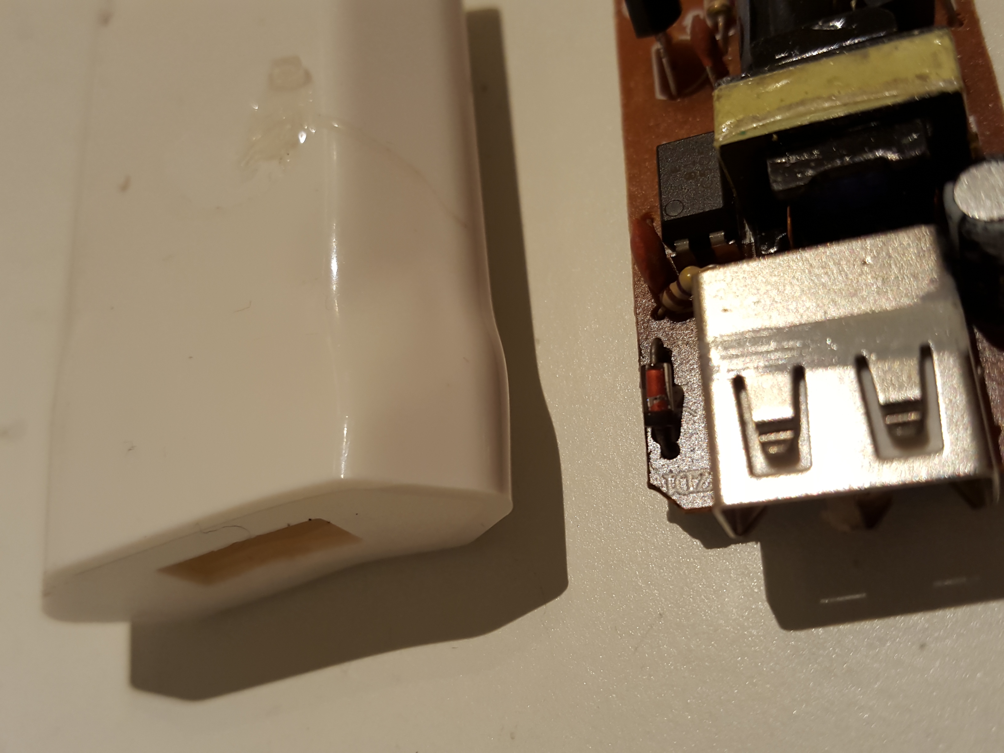
                  Im getting a bit shaky here... how far from disaster (big fire) is this?

                  Controller: Proxmox VM - Home Assistant
                  MySensors GW: Arduino Uno - W5100 Ethernet, Gw Shield Nrf24l01+ 2,4Ghz
                  MySensors GW: Arduino Uno - Gw Shield RFM69, 433mhz
                  RFLink GW - Arduino Mega + RFLink Shield, 433mhz

                  1 Reply Last reply
                  0
                  • rvendrameR Offline
                    rvendrameR Offline
                    rvendrame
                    Hero Member
                    wrote on last edited by
                    #206

                    BTW, the review of HLK PSU should be published in 'few days' according to the guy from http://lygte-info.dk . Can't wait for that!

                    Home Assistant / Vera Plus UI7
                    ESP8266 GW + mySensors 2.3.2
                    Alexa / Google Home

                    1 Reply Last reply
                    0
                    • petewillP Offline
                      petewillP Offline
                      petewill
                      Admin
                      wrote on last edited by
                      #207

                      @sundberg84 Yikes! That is exactly why I started this thread. I don't want to burn my house down...

                      @rvendrame Awesome! Can't wait either!

                      My "How To" home automation video channel: https://www.youtube.com/channel/UCq_Evyh5PQALx4m4CQuxqkA

                      1 Reply Last reply
                      0
                      • rvendrameR Offline
                        rvendrameR Offline
                        rvendrame
                        Hero Member
                        wrote on last edited by
                        #208

                        The review of the hlktech's HLK-PM01 is available here!

                        Home Assistant / Vera Plus UI7
                        ESP8266 GW + mySensors 2.3.2
                        Alexa / Google Home

                        1 Reply Last reply
                        2
                        • F Offline
                          F Offline
                          Fabien
                          wrote on last edited by
                          #209

                          Thank you for the test.

                          1 Reply Last reply
                          0
                          • petewillP Offline
                            petewillP Offline
                            petewill
                            Admin
                            wrote on last edited by
                            #210

                            This is fantastic news!!

                            Would anyone be able to provide a parts list and wiring diagram based on the recommendations from the test site (pasted below)?

                            "A few notes for using it:
                            Electronic wears down faster when warm, especially capacitors, i.e. keep it as cool as possible for long lifetime.
                            I would place a fuse or fusible resistor before the converter, the fuse is not supposed to be replaceable, when it blows it is time to replace the converter.
                            A MOV accross the mains input would probably also be a good idea."
                            http://lygte-info.dk/review/Power Mains to 5V 0.6A Hi-Link HLK-PM01 UK.html

                            Once we have a that info I will update the first post so everyone reading this in the future doesn't have to read through 200+ posts to get to the conclusion. Thanks to everyone who helped with this!!!

                            My "How To" home automation video channel: https://www.youtube.com/channel/UCq_Evyh5PQALx4m4CQuxqkA

                            1 Reply Last reply
                            0
                            • Z Offline
                              Z Offline
                              Zeph
                              Hero Member
                              wrote on last edited by
                              #211

                              The wiring is easy to describe.

                              Put a fuse in line between the "hot" mains AC input and the power supply module input (the "neutral" can go directly to the power supply). Put a MOV across the power supply input (on the PS side of the fuse).

                              For small spikes, the MOV would protect the PS by absorbing most of it. For longer surges, the MOV would cause the fuse to blow, probably sacrificing itself in the process.

                              Maybe others can help with component selection (for 120v and 240v mains). I see that in the case of Littelfuse, the fuse is rated by RMS AC voltage, so a 140v MOV would work for a nominal 120VAC mains). http://www.littelfuse.com/~/media/electronics_technical/application_notes/varistors/littelfuse_selecting_a_littelfuse_varistor_application_note.pdf

                              I don't know if RMS rating is standard, or if some are rated by their DC voltage conduction threshold, but one would want to be sure of that for the brand they are getting.

                              petewillP 1 Reply Last reply
                              0
                              • rvendrameR Offline
                                rvendrameR Offline
                                rvendrame
                                Hero Member
                                wrote on last edited by
                                #212

                                Some more thoughts from the guy who analyzed it:

                                "Hi Ricardo

                                It looks safe enough to me, except I want a fuse or fusible resistor before it. The purpose of the fuse is to blow when the module is worn down and maybe shorts. How fast it wears down will depend on temperature, at very high temperature it might be less than ½ year, at more moderate temperature it might be 10-20 years. The main culprit is the capacitors, their lifetime depends on temperature and quality of the capacitor.
                                Second risk for failure is large transients on the mains that may damage the module, again the fuse is there to prevent things getting out of hand if the module breaks down.

                                The module can get hot if you pack it into the wall, especially if it is inside a lot of insulation. Doing a few test with a DMM and a temperature probe taped to the module inside the wall might be a good idea when running the module near full load.
                                I do not know the stuff used to fill with, but usual it will not easily catch fire."

                                Home Assistant / Vera Plus UI7
                                ESP8266 GW + mySensors 2.3.2
                                Alexa / Google Home

                                M 1 Reply Last reply
                                0
                                • TD22057T Offline
                                  TD22057T Offline
                                  TD22057
                                  Hardware Contributor
                                  wrote on last edited by
                                  #213

                                  @rvendrame Thanks for getting this tested - that's a great result. The high temperatures he was testing at are for running at 1A of output but I thought that the 5V line is just for the Arduino and the radio which aren't going to use much current at all right?

                                  rvendrameR 1 Reply Last reply
                                  0
                                  • TD22057T TD22057

                                    @rvendrame Thanks for getting this tested - that's a great result. The high temperatures he was testing at are for running at 1A of output but I thought that the 5V line is just for the Arduino and the radio which aren't going to use much current at all right?

                                    rvendrameR Offline
                                    rvendrameR Offline
                                    rvendrame
                                    Hero Member
                                    wrote on last edited by
                                    #214

                                    @TD22057 , exactly, under regular load (< 600ma), the unit should not get that hot. Once I get some time I will try the suggestion, by gluing a temp sensor on the unit and put it behind the wall switch.

                                    Perhaps I will add the temp sensor permanently as a extra mySensor on the wall-relay, so I can capture the temp during the upcoming summer days. ;-)

                                    Home Assistant / Vera Plus UI7
                                    ESP8266 GW + mySensors 2.3.2
                                    Alexa / Google Home

                                    1 Reply Last reply
                                    0
                                    • B Offline
                                      B Offline
                                      Bertb
                                      wrote on last edited by
                                      #215

                                      Well, I must say, I am very happy with the result. Thanks for the testing.
                                      So, I am already planning to use it in a number of devices. To avoid too high temperatures in confined boxes, it might be a good idea to glue a temperature fuse to it and wire it in series with the live mains wire. When the temperature rises above, lets say 75 degrees celsius, the fuse breaks down.

                                      1 Reply Last reply
                                      0
                                      • TD22057T Offline
                                        TD22057T Offline
                                        TD22057
                                        Hardware Contributor
                                        wrote on last edited by
                                        #216

                                        It would also be good to link that temp sensor into the arduino. Then it could send out a "help my temp is to high" message before it shuts down. It should be possible to implement an overheated mode which would just blink a status LED on the front of the device and shuts everything else down until the temperature drops. Using the tricks of running a battery powered node should let the arduino power stay low enough for the PSU to cool down while still checking the temperature every few minutes and running the LED. The fuse would then be a fail-safe backup to the overheated mode.

                                        1 Reply Last reply
                                        0
                                        • rvendrameR rvendrame

                                          Some more thoughts from the guy who analyzed it:

                                          "Hi Ricardo

                                          It looks safe enough to me, except I want a fuse or fusible resistor before it. The purpose of the fuse is to blow when the module is worn down and maybe shorts. How fast it wears down will depend on temperature, at very high temperature it might be less than ½ year, at more moderate temperature it might be 10-20 years. The main culprit is the capacitors, their lifetime depends on temperature and quality of the capacitor.
                                          Second risk for failure is large transients on the mains that may damage the module, again the fuse is there to prevent things getting out of hand if the module breaks down.

                                          The module can get hot if you pack it into the wall, especially if it is inside a lot of insulation. Doing a few test with a DMM and a temperature probe taped to the module inside the wall might be a good idea when running the module near full load.
                                          I do not know the stuff used to fill with, but usual it will not easily catch fire."

                                          M Offline
                                          M Offline
                                          mvdarend
                                          wrote on last edited by
                                          #217

                                          @rvendrame said:

                                          Some more thoughts from the guy who analyzed it:

                                          "Hi Ricardo

                                          *It looks safe enough to me, except I want a fuse or fusible resistor before it. The purpose of the fuse is to blow when the module is worn down and maybe shorts.

                                          Would something like this be OK?
                                          http://www.aliexpress.com/store/product/100pcs-LOT-PTC-Resettable-Fuses-TRF250-080-250V-0-08A-80MA-PPTC-Polymeric-PTC-PolySwitch-DIP/1653204_32267664975.html

                                          rvendrameR 1 Reply Last reply
                                          0
                                          Reply
                                          • Reply as topic
                                          Log in to reply
                                          • Oldest to Newest
                                          • Newest to Oldest
                                          • Most Votes


                                          15

                                          Online

                                          11.7k

                                          Users

                                          11.2k

                                          Topics

                                          113.0k

                                          Posts


                                          Copyright 2019 TBD   |   Forum Guidelines   |   Privacy Policy   |   Terms of Service
                                          • Login

                                          • Don't have an account? Register

                                          • Login or register to search.
                                          • First post
                                            Last post
                                          0
                                          • MySensors
                                          • OpenHardware.io
                                          • Categories
                                          • Recent
                                          • Tags
                                          • Popular