Skip to content
  • MySensors
  • OpenHardware.io
  • Categories
  • Recent
  • Tags
  • Popular
Skins
  • Light
  • Brite
  • Cerulean
  • Cosmo
  • Flatly
  • Journal
  • Litera
  • Lumen
  • Lux
  • Materia
  • Minty
  • Morph
  • Pulse
  • Sandstone
  • Simplex
  • Sketchy
  • Spacelab
  • United
  • Yeti
  • Zephyr
  • Dark
  • Cyborg
  • Darkly
  • Quartz
  • Slate
  • Solar
  • Superhero
  • Vapor

  • Default (No Skin)
  • No Skin
Collapse
Brand Logo
  1. Home
  2. Hardware
  3. Which are the *best* NRF24L01+ modules?

Which are the *best* NRF24L01+ modules?

Scheduled Pinned Locked Moved Hardware
310 Posts 42 Posters 259.2k Views 37 Watching
  • Oldest to Newest
  • Newest to Oldest
  • Most Votes
Reply
  • Reply as topic
Log in to reply
This topic has been deleted. Only users with topic management privileges can see it.
  • rvendrameR rvendrame

    @NeverDie said:

    -43.3ua and -42.8ua.

    So the blob module is so good that it is charging your batteries ;-)

    NeverDieN Offline
    NeverDieN Offline
    NeverDie
    Hero Member
    wrote on last edited by
    #154

    @rvendrame said:

    @NeverDie said:

    -43.3ua and -42.8ua.

    So the blob module is so good that it is charging your batteries ;-)

    I'm measuring the current between the Uno 3.3 Female header pin and the Vcc pin on the RF module.

    1 Reply Last reply
    0
    • rvendrameR Offline
      rvendrameR Offline
      rvendrame
      Hero Member
      wrote on last edited by
      #155

      Now talking seriously, maybe the some current is leaking through the other pins (MISO, CE, CS, etc), from arduino to radio? That would could an negative VCC flow I think...

      Home Assistant / Vera Plus UI7
      ESP8266 GW + mySensors 2.3.2
      Alexa / Google Home

      1 Reply Last reply
      0
      • NeverDieN Offline
        NeverDieN Offline
        NeverDie
        Hero Member
        wrote on last edited by
        #156

        It must be that. I wonder how it would measure if I were to use 3.3v on the datapins rather than the 5v the Uno uses.

        1 Reply Last reply
        0
        • rvendrameR Offline
          rvendrameR Offline
          rvendrame
          Hero Member
          wrote on last edited by
          #157

          In theory it would require a logic level converter

          But for sure the atmega is tolerant between 3.3V and 5V. And probably the converter would introduce an error in the u-measurement, I guess.

          Home Assistant / Vera Plus UI7
          ESP8266 GW + mySensors 2.3.2
          Alexa / Google Home

          1 Reply Last reply
          0
          • NeverDieN Offline
            NeverDieN Offline
            NeverDie
            Hero Member
            wrote on last edited by NeverDie
            #158

            I plugged a blob module into the RFToy, which is effectively an 8Mhz Mini Pro running at 3.3v, and used a jig similar to the one before (just no resistor) to route the module Vcc current into the uCurrent.

            This time it is powered through the USB port, and the voltage is downshifted from there.

            New measurements for the blob module:
            Powered Down (Sleep): 3.3uA
            Standby: 67.2uA

            For comparison, I plugged the Itead module (Nordic tracecode 1301CL) into the same apparatus, and this time I got
            Powered Down (Sleep): 0.6uA
            Standby: 22.8uA
            which, within measurement error, I would call the same as when it was hooked up to the Uno.

            1 Reply Last reply
            0
            • NeverDieN Offline
              NeverDieN Offline
              NeverDie
              Hero Member
              wrote on last edited by NeverDie
              #159

              @Zeph: For the NRF24L01+ modules, I now have good enough current measurements that I wanted to get, so I'll be holding off on doing further measurements, at least for now. I want to try the RFM69HW for comparison, but that is outside the scope of this thread.

              1 Reply Last reply
              0
              • NeverDieN Offline
                NeverDieN Offline
                NeverDie
                Hero Member
                wrote on last edited by NeverDie
                #160

                BTW, using just my Fluke 87V multimeter set on the uA setting, the measurements I get are:

                Fluke 87V Itead Module Measurements:
                Powered Down(Sleep): 0.5uA
                Standby: 22.5uA

                and
                Fluke 87V Blob Module Meaasurements:
                Powwred Down(Sleep): 3.0uA
                Standby: 56uA

                and

                Fluke 87V Addicore module from Amazon Measurements:
                Powered Down: 1.2uA
                Standby: 18.2uA

                So, although a bit different than the uCurrent measurements, they seem good enough for separating out the fakes that I have from the genuine article (which at this point the evidence suggests is what the chip in the Itead module is).

                So, good news! Maybe all you need is a DMM with decent uA measurements. If I'd had this information at the very beginning of this thread, it would have saved me a lot of frustration and doubt. Now everyone can be empowered. :smile: The next time you buy modules, you can now easily test them right away and send them back if they're fake! :smile: :smile: :smile:

                hekH 1 Reply Last reply
                0
                • NeverDieN NeverDie

                  BTW, using just my Fluke 87V multimeter set on the uA setting, the measurements I get are:

                  Fluke 87V Itead Module Measurements:
                  Powered Down(Sleep): 0.5uA
                  Standby: 22.5uA

                  and
                  Fluke 87V Blob Module Meaasurements:
                  Powwred Down(Sleep): 3.0uA
                  Standby: 56uA

                  and

                  Fluke 87V Addicore module from Amazon Measurements:
                  Powered Down: 1.2uA
                  Standby: 18.2uA

                  So, although a bit different than the uCurrent measurements, they seem good enough for separating out the fakes that I have from the genuine article (which at this point the evidence suggests is what the chip in the Itead module is).

                  So, good news! Maybe all you need is a DMM with decent uA measurements. If I'd had this information at the very beginning of this thread, it would have saved me a lot of frustration and doubt. Now everyone can be empowered. :smile: The next time you buy modules, you can now easily test them right away and send them back if they're fake! :smile: :smile: :smile:

                  hekH Offline
                  hekH Offline
                  hek
                  Admin
                  wrote on last edited by
                  #161

                  @NeverDie

                  I told you in the fifth post :punch: ;)

                  NeverDieN 1 Reply Last reply
                  0
                  • hekH hek

                    @NeverDie

                    I told you in the fifth post :punch: ;)

                    NeverDieN Offline
                    NeverDieN Offline
                    NeverDie
                    Hero Member
                    wrote on last edited by
                    #162

                    @hek said:

                    @NeverDie

                    I told you in the fifth post :punch: ;)

                    Where exactly did you read it anyway?

                    1 Reply Last reply
                    0
                    • hekH Offline
                      hekH Offline
                      hek
                      Admin
                      wrote on last edited by
                      #163

                      Just a lucky guess.

                      NeverDieN 1 Reply Last reply
                      0
                      • hekH hek

                        Just a lucky guess.

                        NeverDieN Offline
                        NeverDieN Offline
                        NeverDie
                        Hero Member
                        wrote on last edited by NeverDie
                        #164

                        @hek said:

                        Just a lucky guess.

                        What??? You were BS'ing me about reading it? :punch: :astonished:

                        @hek said:

                        You should also compare the power consumption. From what I have read the genuine Nordic module has much better characteristics.

                        1 Reply Last reply
                        0
                        • hekH Offline
                          hekH Offline
                          hek
                          Admin
                          wrote on last edited by
                          #165

                          @NeverDie said:

                          You were BS'ing me then?

                          Hmm.. no.. but I cannot for my mind recollect where I could have read it. So it might just have been a creation of my (weird) mind. :)

                          1 Reply Last reply
                          0
                          • NeverDieN Offline
                            NeverDieN Offline
                            NeverDie
                            Hero Member
                            wrote on last edited by NeverDie
                            #166

                            All's well that ends well. :smile:

                            1 Reply Last reply
                            0
                            • NeverDieN Offline
                              NeverDieN Offline
                              NeverDie
                              Hero Member
                              wrote on last edited by NeverDie
                              #167

                              BTW, I just now measured this surface mount module using the uCurrent, and it measures out at

                              Powered Down (Sleep): 0.7uA
                              Standyby: 22.7uA

                              smt.jpg

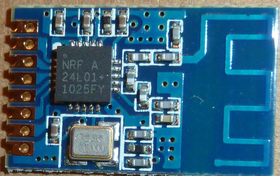
                              Therefore, I deem it genuine. I got it at ICStation two or three months ago:
                              http://www.icstation.com/nrf24l01-rfid-wireless-transmission-module-2dbm-p-4620.html

                              It would help a lot if others here, when you measure your module, would post your measurements and where you got it from, and when. That way we can all benefit from the network effect and make better purchases and possibly avoid bad purchases also.

                              1 Reply Last reply
                              0
                              • Z Offline
                                Z Offline
                                Zeph
                                Hero Member
                                wrote on last edited by Zeph
                                #168

                                Hmm.. no.. but I cannot for my mind recollect where I could have read it. So it might just have been a creation of my (weird) mind. :)

                                Er, check the second sentence of the first (real) paragraph of the OP of the earlier fake nRF24L01+ thread.. Maybe that's where @hek got that impression.

                                And now I am the one who doesn't recall exactly where I read that - but it's undoubtedly from one of the sources I linked to in that post, raised as one of the reasons to be concerned about fakes.

                                1 Reply Last reply
                                0
                                • Z Offline
                                  Z Offline
                                  Zeph
                                  Hero Member
                                  wrote on last edited by Zeph
                                  #169

                                  Those with a low idle/sleep power usage are either Nordic or a quality clone.

                                  Even the blob modules would be workable in non-battery nodes, if they indeed have excellent range and low packet loss.

                                  So I just looked up the Fluke 87V, and the price is a bit high for my budget. So alas, the current state of our fake detection (pun acknowledged) is not a universal solution.

                                  Perhaps a variant with a coulomb counter will arise. Or perhaps using the 200x amplified differential ADC input of the Leonardo or Mega2560 with averaging.

                                  And I think it would be very apropos to distill the knowledge from these many posts into a wiki page. As with many threads here, there's some great info but sometimes it's embedded in hours of reading to find it again.

                                  1 Reply Last reply
                                  0
                                  • Z Offline
                                    Z Offline
                                    Zeph
                                    Hero Member
                                    wrote on last edited by
                                    #170

                                    @NeverDie - now that you have the measurement down, how about measuring receive current, and perhaps carrier-only transmit current? Both of those can be steady state.

                                    I'd still like to know how the various models rate in those areas too, while you have the setup handy.

                                    NeverDieN 1 Reply Last reply
                                    0
                                    • Z Zeph

                                      @NeverDie - now that you have the measurement down, how about measuring receive current, and perhaps carrier-only transmit current? Both of those can be steady state.

                                      I'd still like to know how the various models rate in those areas too, while you have the setup handy.

                                      NeverDieN Offline
                                      NeverDieN Offline
                                      NeverDie
                                      Hero Member
                                      wrote on last edited by NeverDie
                                      #171

                                      @Zeph said:

                                      ...carrier-only transmit current?

                                      What is "carrier only transmit current", and how would I measure that?

                                      1 Reply Last reply
                                      0
                                      • Z Offline
                                        Z Offline
                                        Zeph
                                        Hero Member
                                        wrote on last edited by Zeph
                                        #172

                                        Register 6 (RF_SETUP) bit 7 (CONT_WAVE) on p 55 of the rev 1 datasheet.

                                        Set it up to transmit constantly (carrier only, no data) and measure the Vcc current usage. (For a short time obviously!) Probably close to the current it would take while sending data.

                                        Likewise, measure current while waiting to receive with no actual data coming in (unless that's what your standby is).

                                        I haven't tried the constant-wave transmit mode, I just remembered that it was mentioned in the datasheet.

                                        1 Reply Last reply
                                        0
                                        • NeverDieN Offline
                                          NeverDieN Offline
                                          NeverDie
                                          Hero Member
                                          wrote on last edited by NeverDie
                                          #173

                                          For the IcStation module I profiled directly above, the receive current (using the microcurrent) measures out at 8.4mA using this sketch to put the module into receive mode:

                                          /* Adapted by NeverDie on 8/11/2015 for uCurrent measurements.
                                           *  Sketch for measuring receive current.
                                           */
                                          
                                          /*
                                           Copyright (C) 2011 J. Coliz <maniacbug@ymail.com>
                                          
                                           This program is free software; you can redistribute it and/or
                                           modify it under the terms of the GNU General Public License
                                           version 2 as published by the Free Software Foundation.
                                           
                                           TMRh20 2014 - Updates to the library allow sleeping both in TX and RX modes:
                                                TX Mode: The radio can be powered down (.9uA current) and the Arduino slept using the watchdog timer
                                                RX Mode: The radio can be left in standby mode (22uA current) and the Arduino slept using an interrupt pin
                                           */
                                          
                                          /**
                                           * Example RF Radio Ping Pair which Sleeps between Sends
                                           *
                                           * This is an example of how to use the RF24 class to create a battery-
                                           * efficient system.  It is just like the GettingStarted_CallResponse example, but the
                                           * ping node powers down the radio and sleeps the MCU after every
                                           * ping/pong cycle, and the receiver sleeps between payloads.
                                           *
                                           * Write this sketch to two different nodes,
                                           * connect the role_pin to ground on one.  The ping node sends the current
                                           * time to the pong node, which responds by sending the value back.  The ping
                                           * node can then see how long the whole cycle took.
                                           */
                                          
                                          #include <SPI.h>
                                          #include <avr/sleep.h>
                                          #include <avr/power.h>
                                          #include "nRF24L01.h"
                                          #include "RF24.h"
                                          #include "printf.h"
                                          
                                          
                                          // Set up nRF24L01 radio on SPI bus plus pins 7 & 8
                                          RF24 radio(7,8);
                                          
                                          // sets the role of this unit in hardware.  Connect to GND to be the 'pong' receiver
                                          // Leave open to be the 'ping' transmitter
                                          const int role_pin = 5;
                                          
                                          const uint64_t pipes[2] = { 0xF0F0F0F0E1LL, 0xF0F0F0F0D2LL };   // Radio pipe addresses for the 2 nodes to communicate.
                                          
                                          // Role management
                                          // Set up role.  This sketch uses the same software for all the nodes
                                          // in this system.  Doing so greatly simplifies testing.  The hardware itself specifies
                                          // which node it is.
                                          
                                          // The various roles supported by this sketch
                                          typedef enum { role_ping_out = 1, role_pong_back } role_e;
                                          
                                          // The debug-friendly names of those roles
                                          const char* role_friendly_name[] = { "invalid", "Ping out", "Pong back"};
                                          
                                          // The role of the current running sketch
                                          role_e role;
                                          
                                          void setup(){
                                          
                                            // set up the role pin
                                            pinMode(role_pin, INPUT);
                                            digitalWrite(role_pin,HIGH);
                                            delay(20); // Just to get a solid reading on the role pin
                                          
                                            // read the address pin, establish our role
                                            if ( digitalRead(role_pin) )
                                              role = role_ping_out;
                                            else
                                              role = role_pong_back;
                                          
                                            Serial.begin(57600);
                                            while (!Serial) {
                                              ; // wait for serial port to connect. Needed for Leonardo only
                                            }
                                            printf_begin();
                                            printf("\n\rRF24/examples/pingpair_sleepy/\n\r");
                                            printf("ROLE: %s\n\r",role_friendly_name[role]);
                                          
                                            radio.begin();
                                          
                                            // Open pipes to other nodes for communication
                                          
                                            // This simple sketch opens two pipes for these two nodes to communicate
                                            // back and forth.
                                            // Open 'our' pipe for writing
                                            // Open the 'other' pipe for reading, in position #1 (we can have up to 5 pipes open for reading)
                                          
                                            if ( role == role_ping_out ) {
                                              radio.openWritingPipe(pipes[0]);
                                              radio.openReadingPipe(1,pipes[1]);
                                            } else {
                                              radio.openWritingPipe(pipes[1]);
                                              radio.openReadingPipe(1,pipes[0]);
                                            }
                                          
                                            
                                            // Dump the configuration of the rf unit for debugging
                                            radio.printDetails();
                                          }
                                          
                                          void loop(){
                                          
                                            radio.startListening();
                                           
                                          }


                                          I can't promise to do the other measurements, as I'm facing some deadlines I need to attend to. If anyone else would like to pick up the baton and carry it forward, please feel free.

                                          1 Reply Last reply
                                          0
                                          Reply
                                          • Reply as topic
                                          Log in to reply
                                          • Oldest to Newest
                                          • Newest to Oldest
                                          • Most Votes


                                          17

                                          Online

                                          11.7k

                                          Users

                                          11.2k

                                          Topics

                                          113.0k

                                          Posts


                                          Copyright 2019 TBD   |   Forum Guidelines   |   Privacy Policy   |   Terms of Service
                                          • Login

                                          • Don't have an account? Register

                                          • Login or register to search.
                                          • First post
                                            Last post
                                          0
                                          • MySensors
                                          • OpenHardware.io
                                          • Categories
                                          • Recent
                                          • Tags
                                          • Popular