Skip to content
  • MySensors
  • OpenHardware.io
  • Categories
  • Recent
  • Tags
  • Popular
Skins
  • Light
  • Brite
  • Cerulean
  • Cosmo
  • Flatly
  • Journal
  • Litera
  • Lumen
  • Lux
  • Materia
  • Minty
  • Morph
  • Pulse
  • Sandstone
  • Simplex
  • Sketchy
  • Spacelab
  • United
  • Yeti
  • Zephyr
  • Dark
  • Cyborg
  • Darkly
  • Quartz
  • Slate
  • Solar
  • Superhero
  • Vapor

  • Default (No Skin)
  • No Skin
Collapse
Brand Logo
  1. Home
  2. Hardware
  3. Which are the *best* NRF24L01+ modules?

Which are the *best* NRF24L01+ modules?

Scheduled Pinned Locked Moved Hardware
310 Posts 42 Posters 259.3k Views 37 Watching
  • Oldest to Newest
  • Newest to Oldest
  • Most Votes
Reply
  • Reply as topic
Log in to reply
This topic has been deleted. Only users with topic management privileges can see it.
  • dougD doug

    @rollercontainer

    I have found that the NRF24L01+ PA LNA radios I have, have 100% packet loss and will not sleep if driven with voltages over 3.0v I have dropped the supply to 2.7v and now have minimal packet loss and the radios will sleep at all power level settings.

    Current draw is 4.7uA including 328P + RTC when asleep as measured with a uCurrent Gold.

    NeverDieN Offline
    NeverDieN Offline
    NeverDie
    Hero Member
    wrote on last edited by
    #257

    @doug said:

    @rollercontainer

    I have found that the NRF24L01+ PA LNA radios I have, have 100% packet loss and will not sleep if driven with voltages over 3.0v I have dropped the supply to 2.7v and now have minimal packet loss and the radios will sleep at all power level settings.

    Current draw is 4.7uA including 328P + RTC when asleep as measured with a uCurrent Gold.

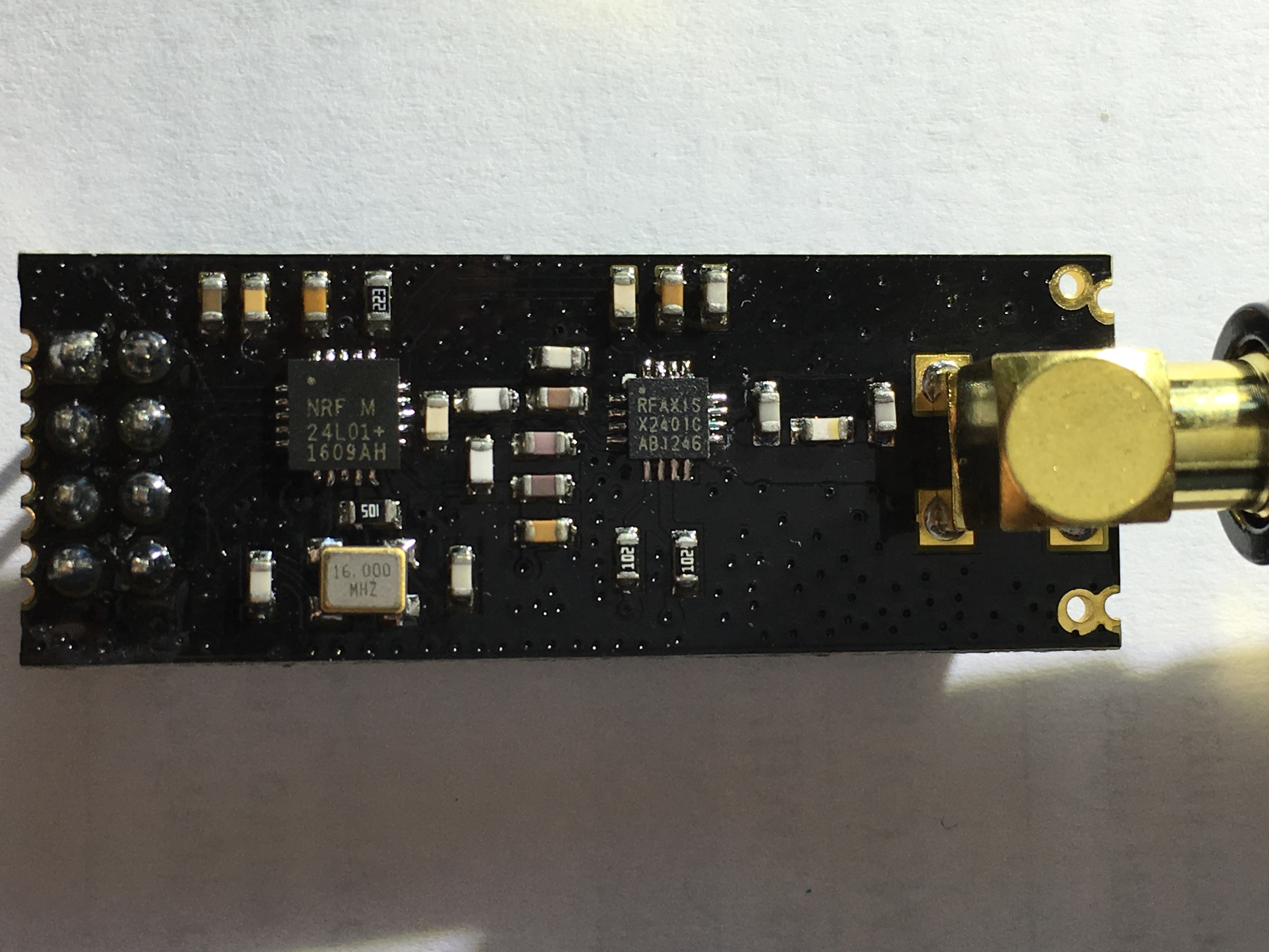
    Would you please post a photo of what the module looks like? It might offer up some clues.

    1 Reply Last reply
    0
    • dougD Offline
      dougD Offline
      doug
      wrote on last edited by
      #258

      0_1466444120491_image.jpeg

      Here is a photo of the module

      parachutesjP 2 Replies Last reply
      0
      • dougD doug

        0_1466444120491_image.jpeg

        Here is a photo of the module

        parachutesjP Offline
        parachutesjP Offline
        parachutesj
        wrote on last edited by parachutesj
        #259

        @doug I do have the same ones bought at alice from the shop link. I also have issues and basically not functioning. I will try your "fix" and see how it goes. Did you do some shielding?

        Cheers,
        SJ

        SparkmanS 1 Reply Last reply
        0
        • dougD doug

          0_1466444120491_image.jpeg

          Here is a photo of the module

          parachutesjP Offline
          parachutesjP Offline
          parachutesj
          wrote on last edited by
          #260

          @doug I did some quick tests and I can confim that the modules work better with less voltage. I made best experience with 2.5-2.6V. However they are still much much worse than all others I have and not worth the hassle IMHO.

          NeverDieN alexsh1A 2 Replies Last reply
          0
          • parachutesjP parachutesj

            @doug I did some quick tests and I can confim that the modules work better with less voltage. I made best experience with 2.5-2.6V. However they are still much much worse than all others I have and not worth the hassle IMHO.

            NeverDieN Offline
            NeverDieN Offline
            NeverDie
            Hero Member
            wrote on last edited by
            #261

            @parachutesj said:

            . However they are still much much worse than all others I have and not worth the hassle IMHO.

            Which other ones do you have that perform better? It would be very useful to know.

            parachutesjP 1 Reply Last reply
            0
            • parachutesjP parachutesj

              @doug I do have the same ones bought at alice from the shop link. I also have issues and basically not functioning. I will try your "fix" and see how it goes. Did you do some shielding?

              Cheers,
              SJ

              SparkmanS Offline
              SparkmanS Offline
              Sparkman
              Hero Member
              wrote on last edited by
              #262

              @parachutesj said:

              @doug I do have the same ones bought at alice from the shop link. I also have issues and basically not functioning. I will try your "fix" and see how it goes. Did you do some shielding?

              Cheers,
              SJ

              FWIW, I use these exact ones and I get very good range with them, without additional shielding.

              Cheers
              Al

              1 Reply Last reply
              0
              • NeverDieN NeverDie

                @parachutesj said:

                . However they are still much much worse than all others I have and not worth the hassle IMHO.

                Which other ones do you have that perform better? It would be very useful to know.

                parachutesjP Offline
                parachutesjP Offline
                parachutesj
                wrote on last edited by
                #263

                @NeverDie
                I have the shielded ones from IC-Station:
                http://www.icstation.com/22dbm-100mw-nrf24l01ppalna-wireless-transmission-module-p-4677.html

                Back to the ones discussed here:
                When doing the basic test from earlier in this thread I am getting massive packet loss even if the modules are very close together. Ok, maybe it needs to be shielded, power too high etc and tried having them separated with no luck, still massive packet losses. Of course this is no scientific research.

                Without tweaking, modifications, special antenna orientation the shielded IC-Station ones just worked for me. I am not saying the others don't work, they just perform not in my setup very well.

                Also as a comparison, I have some cheep modules from Aliexpress they outperform the ampliefied ones (at least within the house):
                http://www.aliexpress.com/item/10PCS-LOT-NRF24L01-wireless-data-transmission-module-2-4G-the-NRF24L01-upgrade-version/1593276910.html
                alt text

                Those modules look very poor build to be honest but seem to be ok. They came in one single back, some pins bent but nothing which couldn't be fixed. Minor packet losses and antenna orientation seems to be key.

                In comparison, I also bought some more expensive ones, which claim to be original:
                http://www.aliexpress.com/item/Free-shipping-Original-Genuine-NRF24L01-Wireless-Module-2-4G-wireless-communication-module-2-54mm-Interface-2/1781618813.html
                alt text
                Those came in a nice protected box and look very well made.
                They work, I even think better than the others - but I already blew two of them. Not sure what went wrong :-(

                Just received some SMD ones which haven't been tested yet.

                1 Reply Last reply
                0
                • loralgL Offline
                  loralgL Offline
                  loralg
                  wrote on last edited by
                  #264

                  Does anyone know if the NRF24L01 and the +PA+LNA modules can be mixed and matched? Will the regular modules and the longer range versions talk to each other? I would like to use one of the long range modules on my gateway in the house and on some sensors around my yard that are a fair distance from my house. But then to save some money I was wondering if I could use the regular modules around the rest of my house. My concern is if I use regular modules on the sensors in my house if they will still be able to communicate with the longer range version module I have on my gateway?

                  A 1 Reply Last reply
                  0
                  • loralgL loralg

                    Does anyone know if the NRF24L01 and the +PA+LNA modules can be mixed and matched? Will the regular modules and the longer range versions talk to each other? I would like to use one of the long range modules on my gateway in the house and on some sensors around my yard that are a fair distance from my house. But then to save some money I was wondering if I could use the regular modules around the rest of my house. My concern is if I use regular modules on the sensors in my house if they will still be able to communicate with the longer range version module I have on my gateway?

                    A Offline
                    A Offline
                    arraWX
                    wrote on last edited by arraWX
                    #265

                    @loralg I successfully use a nRF24L01+PA+LNA on the gateway and regular nRF24L01+ on the sensors.

                    There is a lot of information and hints available in the forum regarding the nRF24L01+PA+LNA . See e.g. here:
                    https://forum.mysensors.org/topic/3719/nrf24l01-vs-nrf24l01-pa-lna/2

                    In my case, however, the nRF24L01+PA+LNA works fine without any fix or special attention.

                    1 Reply Last reply
                    2
                    • afenoA Offline
                      afenoA Offline
                      afeno
                      wrote on last edited by
                      #266

                      Hello,

                      What is the best way to measure the performance of one module at a given distance? I mean, how can I measure the number of packets lost?
                      Does anybody already created a "performace test sketch" to perofrm a better test?

                      NeverDieN 1 Reply Last reply
                      0
                      • afenoA afeno

                        Hello,

                        What is the best way to measure the performance of one module at a given distance? I mean, how can I measure the number of packets lost?
                        Does anybody already created a "performace test sketch" to perofrm a better test?

                        NeverDieN Offline
                        NeverDieN Offline
                        NeverDie
                        Hero Member
                        wrote on last edited by
                        #267

                        @afeno said:

                        Hello,

                        What is the best way to measure the performance of one module at a given distance? I mean, how can I measure the number of packets lost?
                        Does anybody already created a "performace test sketch" to perofrm a better test?

                        I posted a sketch earlier in this thread.

                        1 Reply Last reply
                        1
                        • parachutesjP parachutesj

                          @doug I did some quick tests and I can confim that the modules work better with less voltage. I made best experience with 2.5-2.6V. However they are still much much worse than all others I have and not worth the hassle IMHO.

                          alexsh1A Offline
                          alexsh1A Offline
                          alexsh1
                          wrote on last edited by
                          #268

                          @parachutesj said:

                          @doug I did some quick tests and I can confim that the modules work better with less voltage. I made best experience with 2.5-2.6V. However they are still much much worse than all others I have and not worth the hassle IMHO.

                          How did you decrease the voltage on nrf24l01+ PA? I have a voltage regulator providing 3.3V.

                          afenoA parachutesjP 2 Replies Last reply
                          1
                          • dougD Offline
                            dougD Offline
                            doug
                            wrote on last edited by
                            #269

                            I have also found that the higher the voltage the more capacitance you need. Guess that makes sense. Still can't get them to work reliably at 3.3v though.

                            I am realising the important thing is a good power supply you need to choose the right regulator to ensure the voltage doesn't tank too far when the current spikes (~180mA). caps help to some degree and I have found ceramic are better than the aluminium ones.

                            I am now using a single cell lipo and 2 regulators one at 3.3 and one at 2.7 for the radio. Also easier to get a low IQ with 2 regulators rather than one big one.

                            I am still learning and need to start doing some playing with a greater range of modules. Especially as your experience of these is that they are pretty poor.

                            1 Reply Last reply
                            0
                            • alexsh1A alexsh1

                              @parachutesj said:

                              @doug I did some quick tests and I can confim that the modules work better with less voltage. I made best experience with 2.5-2.6V. However they are still much much worse than all others I have and not worth the hassle IMHO.

                              How did you decrease the voltage on nrf24l01+ PA? I have a voltage regulator providing 3.3V.

                              afenoA Offline
                              afenoA Offline
                              afeno
                              wrote on last edited by
                              #270

                              @alexsh1

                              I'm wondering the same as @alexsh1 . How can I get 2.5-2.6V? There is an easy/cheap way to do it?

                              AWIA 1 Reply Last reply
                              0
                              • afenoA afeno

                                @alexsh1

                                I'm wondering the same as @alexsh1 . How can I get 2.5-2.6V? There is an easy/cheap way to do it?

                                AWIA Offline
                                AWIA Offline
                                AWI
                                Hero Member
                                wrote on last edited by
                                #271

                                @afeno The cheap way is a diode in the vcc line. The voltage drop over a normal silicon diode (i.e. 1N4001) is around 0.7V. This has proven to be a working solution.

                                1 Reply Last reply
                                1
                                • alexsh1A alexsh1

                                  @parachutesj said:

                                  @doug I did some quick tests and I can confim that the modules work better with less voltage. I made best experience with 2.5-2.6V. However they are still much much worse than all others I have and not worth the hassle IMHO.

                                  How did you decrease the voltage on nrf24l01+ PA? I have a voltage regulator providing 3.3V.

                                  parachutesjP Offline
                                  parachutesjP Offline
                                  parachutesj
                                  wrote on last edited by
                                  #272

                                  @alexsh1
                                  as it was just a test, I used a table power supply to have the exact voltages.

                                  1 Reply Last reply
                                  0
                                  • afenoA Offline
                                    afenoA Offline
                                    afeno
                                    wrote on last edited by
                                    #273

                                    Hello,
                                    I'm creating a "ping" sketch to measure the % of packet lost using the tmrh20 library. I will post it once it is finished but it is just a modification of the "GettingStarted" sketch.

                                    It is very simple:

                                    • Node 1 send a value to node 2.
                                    • Node 2 receive the message and send it back to node 1.
                                    • Node 1 receive the message.

                                    I'm measuring the number of packets lost and the turnaround time.

                                    But doing some tests, I realised about something very strange that I don't understand...

                                    Based on the sketch described above, both the node 1 and 2 are sending and receiving the same amount of data.
                                    They both use the same commands to send and receive.
                                    I have two hardware sensors/devices (let's call it A and B ) based on arduinos nano.

                                    When I use A as Node 1 it gets 0.2% of packets lost. (B is used as Node 2)
                                    When I use B as Node 1 it gets 15% of packets lost!! (A is used as Node 2)

                                    Remember: Both nodes are sending and receiving the same amount of data.

                                    I understand that the current, radio, noise, etc. might have an impact on the performance and range but why it is working fine on one way? And not in the other way? This is making me crazy. Both sensors are sending and receiving the same data. If one of them is not sending (or receiving) well, the performance still should be the same independent on who is acting as node 1 or 2.

                                    What I am missing?

                                    Thank you!

                                    NeverDieN 1 Reply Last reply
                                    0
                                    • afenoA afeno

                                      Hello,
                                      I'm creating a "ping" sketch to measure the % of packet lost using the tmrh20 library. I will post it once it is finished but it is just a modification of the "GettingStarted" sketch.

                                      It is very simple:

                                      • Node 1 send a value to node 2.
                                      • Node 2 receive the message and send it back to node 1.
                                      • Node 1 receive the message.

                                      I'm measuring the number of packets lost and the turnaround time.

                                      But doing some tests, I realised about something very strange that I don't understand...

                                      Based on the sketch described above, both the node 1 and 2 are sending and receiving the same amount of data.
                                      They both use the same commands to send and receive.
                                      I have two hardware sensors/devices (let's call it A and B ) based on arduinos nano.

                                      When I use A as Node 1 it gets 0.2% of packets lost. (B is used as Node 2)
                                      When I use B as Node 1 it gets 15% of packets lost!! (A is used as Node 2)

                                      Remember: Both nodes are sending and receiving the same amount of data.

                                      I understand that the current, radio, noise, etc. might have an impact on the performance and range but why it is working fine on one way? And not in the other way? This is making me crazy. Both sensors are sending and receiving the same data. If one of them is not sending (or receiving) well, the performance still should be the same independent on who is acting as node 1 or 2.

                                      What I am missing?

                                      Thank you!

                                      NeverDieN Offline
                                      NeverDieN Offline
                                      NeverDie
                                      Hero Member
                                      wrote on last edited by
                                      #274

                                      @afeno
                                      Interesting asymmetry.

                                      This sounds basically the same as the sketch I posted earlier. Perhaps post a photo of the two nodes? Maybe something will jump out.

                                      If you really want to solve it, try also
                                      testing the packet loss on the individual links instead of only roundtrip. I suspect it will reveal something.

                                      1 Reply Last reply
                                      0
                                      • afenoA Offline
                                        afenoA Offline
                                        afeno
                                        wrote on last edited by
                                        #275

                                        Sorry for my ignorance... But how can I measure the packets lost on individual links?
                                        Do you mean to check the packets lost in a 1-way trip? Only from node1 to node2?

                                        1 Reply Last reply
                                        0
                                        • cimba007C Offline
                                          cimba007C Offline
                                          cimba007
                                          wrote on last edited by cimba007
                                          #276

                                          Hello,

                                          I thought it might be best to contribute to this thread rather then making a new one. I have some NRF24L01+ for like 2-3 years. Some of them are the normal ones and a few LNA+PA.

                                          The following explanation requires some "advanced" knowledge about the RF24 library and the test-sketch I added. Please forgive me as I was not able to write a more simple sketch and explanation.

                                          From day one I had problems using the modules at 250kbps with autoack. The Reception (RPD) was very poor and I had very high packet loss.

                                          For a few days now I have been tinkering with mysensors and just recently noticed .. wait what???

                                          250kbps + autoack is default.

                                          As mysensors is not ideal for testing modules I used another well known library:

                                          http://tmrh20.github.io/RF24/

                                          To get access to a very important register to debug autoack issues I modified "RF24.h" to get the low level functions public:

                                          **public:**
                                          
                                            /**
                                             * @name Low-level internal interface.
                                             *
                                             *  Protected methods that address the chip directly.  Regular users cannot
                                             *  ever call these.  They are documented for completeness and for developers who
                                             *  may want to extend this class.
                                             */
                                          

                                          After that I hooked up an single WS2812B-LED to pin 4 and tinkerd together a little test-sketch:

                                          0_1469476423782_getting_started_250kbps_minimum2.zip

                                          Note: You have to write the values 0 and 1 to EEPROM.Address 0 ONCE. 0 is the static pong back node and 1 is the mobile node with the WS2812B LED. This allows moving freely and check reception in your home.

                                          After writing the values to the eeprom you can comment out the code and don't have to worry when uploading the sketch to the "pongback"-node or the mobile "ping" node.

                                          //EEPROM.write(0,0); // 0 = PongBack
                                          

                                          If you don't want to use the WS2812B you have to remove some code but that should not be too hard.

                                          The important parts come now:

                                          settings[autoack] = 0;
                                          settings[retry] = 15;
                                          settings[delay_rf] = 15;

                                          Disabling autoack I could get an improved reading of RDP and very little PacketLoss. I now can cover distanced much larger like through 2-3 walls more then before.

                                          My modules are all powered from 3,3V dedicated LDO or 3V (2x AA) Battery and run @ 8MHz

                                          Long story short:

                                          If you have reception problems even after checking your Supply and even after trying the "ugly fix" and still got nowhere .. i suggest your try disabling auto ack. Although this it not intiutive on mysensors and would leave you vulnerable to packetloss I suggest you to test it out with this library (http://tmrh20.github.io/RF24/) and my example sketch.

                                          Sorry for not presenting a whole solution but I thought it might be worth to point people having reception problems into one possible "direction".

                                          PS: Autoack works fine on my modules if I switch to 1MBPS so this might be viable too.

                                          1 Reply Last reply
                                          0
                                          Reply
                                          • Reply as topic
                                          Log in to reply
                                          • Oldest to Newest
                                          • Newest to Oldest
                                          • Most Votes


                                          16

                                          Online

                                          11.7k

                                          Users

                                          11.2k

                                          Topics

                                          113.0k

                                          Posts


                                          Copyright 2019 TBD   |   Forum Guidelines   |   Privacy Policy   |   Terms of Service
                                          • Login

                                          • Don't have an account? Register

                                          • Login or register to search.
                                          • First post
                                            Last post
                                          0
                                          • MySensors
                                          • OpenHardware.io
                                          • Categories
                                          • Recent
                                          • Tags
                                          • Popular