Efficiency of Voltage Boosters
-
(Note resurrected post) @therik I used to think that you could run the MySensor stuff just using two batteries connected directly to the processor but came to the conclusion that's a bad idea. First, to get the best out of some sensors running them off a fixed Voltage is preferable.
Secondly two alkaline AAs supply about 2.4V to 2.6V (during most of their operational life time) and the 3.3V CPUs have the brownout set to 2.7 V (typ). So if you use this method, you need to ensure the brown out detector (BOD) fuses are set to disable the brownout detection completely. Doing it in software is not sufficient, as the BOD is automatically re-enabled as soon as the CPU comes out of sleep.
The CPU spec shows the maximum Frequency vs. VCC line for between 1.8 V and 2.7 V. The line equation is Vmin = (F-k)/m, where from the spec k = -8 and m =6.6666 so for 8 MHz: Vmin = 2.4V Towards the end of their life two AAs will go below this Voltage. What happens then? With an inverter you can monitor the battery Voltage and trigger an alarm when it gets really, really low.
Also with the inverter you can squeeze every last ounce of juice out of them and everything will still work.
@axillent Totally agree about charging batteries - probably more hassle than it's worth. Depending on the application, just solar charging a super capacitor could work well. Imagine a temperature sensor reporting back every fifteen minutes and it consumes say 30ma at 3V3 for 0.5 seconds while it reports and we use one of these:
https://www.sparkfun.com/products/746
time roughly = (C/I)*(Vmax-Vmin)
so say we use say a Vmax of 2V and Vmin of 1V and use that to power an inverter to 3V3. Also assume we draw 100 mA at 1V, which is about 30 mA at 3V3 for the CPU and radio. We have a ten Farad cap but it's a bit out of tolerance, so it's actually only five Farads.
(5/0.1)*(2-1)= 50 seconds
That allows for one hundred 0.5 second samples to sent before the cap is "flat", which is 25 hours if sent every 15 minutes. So it looks like it could work OK. Should work for @HeK in Sweden where the shortest day is only about 7 hours long, with the main problem is keeping snow off the solar panel.
-
Just adding to the above. It does make sense to run the radio directly off the battery (1V9 to 3V6) but two problems remain: the CPU brownout detector and the minimum Voltage required to run the CPU, which is 2V4 at 8 MHz.. See also:
http://forum.micasaverde.com/index.php/topic,20078.msg164716.html#msg164716
The radio must have a supply Voltage of 2V7 to 3V3 if the input signals are greater than 3V6. you would encounter this when running a CPU at 5V, which hopefully you wouldn't be doing on a battery powered set up.
@a-lurker If brownout detection is disabled we could power atmega328p with 1.9V minimum, but frequency of operation will decrease.
I know you get it right, i just want to standout that there is no problem of operation at low voltage if we know 2 thinks:- disable BOD (no soft)
- we get lower frequency
-
There are a few subjects in this valuable thread.
One is the best type of capacitor to use across the power and ground of the nRF24L01+ module. I'm very interested in that. My earliest tests were frustrating, I was busy trying to figure out what was wrong with the software (before I came here by the way), but it turned out to be power and/or too long SPI wires. A cap across the power at the module made a great difference. So I'm tending towards always doing that in the future, and I'd like to know what kind to stock up on.
I'm seeing some opinion that tantalum would be better, some that it has too high ESR. So a low ESR electrolytic (probable aluminum polymer) would be better. Or maybe a ceramic is better still, and cheap.
Are there any recommended caps below 50 cents in small quantities? Is there anything from eBay or Tayda or are those all junk for our purposes? If not, Digikey or Mouser is OK, tho the minimum shipping raises the effective cost per unit substantially for small quantities (and I may not have a large order to combine it with for months).
There is a variation of this question which is about caps for use with noisy boost converters. I am thinking that a good cap for that purpose would also be a good cap for use with the tranceiver in general - low ESR and with an appropriate value, with low leakage. (In another case the noise of a sensor or actuator might be what needs to be filtered out rather than a boost voltage converter).
-
I changed the capacitor that I used for my radios from 4.7 mF into 220 mF and I can only say thank you for this discussion, it is really immediately much better :)
-
I changed the capacitor that I used for my radios from 4.7 mF into 220 mF and I can only say thank you for this discussion, it is really immediately much better :)
@marceltrapman mF as in milli or micro? :) µF I suppose..
-
I changed the capacitor that I used for my radios from 4.7 mF into 220 mF and I can only say thank you for this discussion, it is really immediately much better :)
-
@marceltrapman You're welcome :)
I tried 220µF myself now (EU keyoard can write µ with alt-gr+m or (ctrl+alt m if alt+gr is missing))
much better, I first used 33µF and then 100µF but 220µF is a winner.
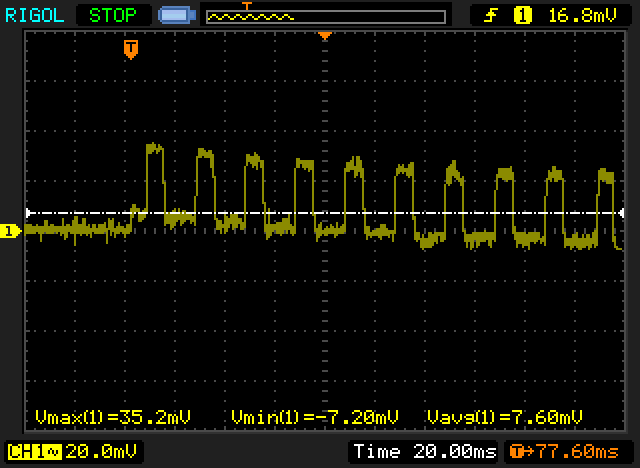
The wierd thing is that I cant measure any difference with 33µF or 220µF with my oscilloscope. but with no cap at all my arduino nano 3.3v looks like this: (AC coupled)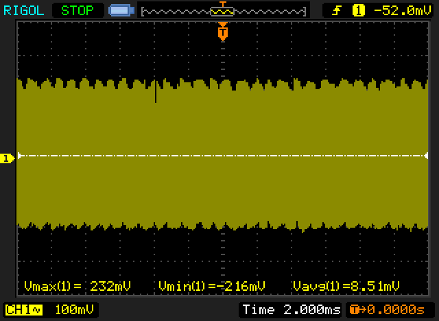
And wit cap (33µF or 220µF makes no difference at all..) But it works much better..
-
@marceltrapman You're welcome :)
I tried 220µF myself now (EU keyoard can write µ with alt-gr+m or (ctrl+alt m if alt+gr is missing))
much better, I first used 33µF and then 100µF but 220µF is a winner.
The wierd thing is that I cant measure any difference with 33µF or 220µF with my oscilloscope. but with no cap at all my arduino nano 3.3v looks like this: (AC coupled)
And wit cap (33µF or 220µF makes no difference at all..) But it works much better..
-
@Yveaux As mentioned I am still learning about this stuff.
The question I have right now is, a bit off topic, at which pin do you measure this?
Is that simply vcc on the radio? -
@marceltrapman You're welcome :)
I tried 220µF myself now (EU keyoard can write µ with alt-gr+m or (ctrl+alt m if alt+gr is missing))
much better, I first used 33µF and then 100µF but 220µF is a winner.
The wierd thing is that I cant measure any difference with 33µF or 220µF with my oscilloscope. but with no cap at all my arduino nano 3.3v looks like this: (AC coupled)
And wit cap (33µF or 220µF makes no difference at all..) But it works much better..
@Damme said:
much better, I first used 33µF and then 100µF but 220µF is a winner.
The wierd thing is that I cant measure any difference with 33µF or 220µF with my oscilloscope.So I think you are saying that you are not seeing a visual difference (on the o'scope) between 33uF and 220uF, but you are seeing better real world performance with the latter?
Do the different capacitors have the same spec's? I'm wondering if the capacity is the only significant change, or if the different values of cap you tested have different specs (eg: ESR) or even diff technology.
-
@Damme said:
much better, I first used 33µF and then 100µF but 220µF is a winner.
The wierd thing is that I cant measure any difference with 33µF or 220µF with my oscilloscope.So I think you are saying that you are not seeing a visual difference (on the o'scope) between 33uF and 220uF, but you are seeing better real world performance with the latter?
Do the different capacitors have the same spec's? I'm wondering if the capacity is the only significant change, or if the different values of cap you tested have different specs (eg: ESR) or even diff technology.
@Zeph Exacly, I first used 3.3µf and there I see voltage drop. But almost no measurable difference with 33µF or 220µF. But I get less failed transmission with the larger cap.
They are all the same brand (some cheap Chinese unknown (to me) brand, "Chong" (yay!))
All 16v, and all electrolytic. I don't have any ESR meter, thinking of trying to measure it with oscilloscope and function generator.. (Or I'll just bu one :))I bought them from ebay in a large 1800pcs asorted pack.
-
New data on the XC9140A331 3.3 V voltage booster. This looks like a nice IC with low quiescent current and an improvement over the stock "china" 3.3 V booster.
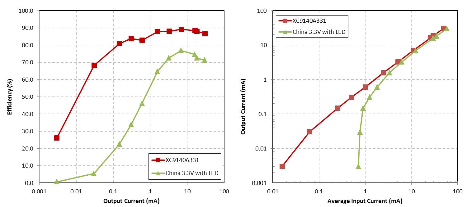
This option can be purchased from Digikey for $0.90, with a total bill of materials of $1.34 (in quantity, minus a PCB). It is also a nice size SOT23-5, not too small to hand solder.
Thoughts?
-
New data on the XC9140A331 3.3 V voltage booster. This looks like a nice IC with low quiescent current and an improvement over the stock "china" 3.3 V booster.
This option can be purchased from Digikey for $0.90, with a total bill of materials of $1.34 (in quantity, minus a PCB). It is also a nice size SOT23-5, not too small to hand solder.
Thoughts?
-
I look forward to a test of the TPS61222 used in the MySensors Battery board - I see the chip on your list and hope you will be checking it.
Felix at lowpowerlab (http://lowpowerlab.com/blog/2014/06/08/powershield-r2-released/) has switched from the TPS61220 to the LTC3525 for stability reasons. That's a 5v chip, tho but maybe there's a related one as a contender.
-
How do you guys measure <mA accuratly? Using mr Jones's µCurrent?
Hello! It looks like you're interested in this conversation, but you don't have an account yet.
Getting fed up of having to scroll through the same posts each visit? When you register for an account, you'll always come back to exactly where you were before, and choose to be notified of new replies (either via email, or push notification). You'll also be able to save bookmarks and upvote posts to show your appreciation to other community members.
With your input, this post could be even better 💗
Register Login