Battery Sensor v 1.0 PCB
-
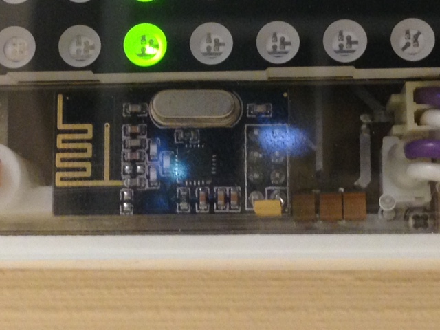
about capacitor for radio. Attached you can see picture from one of my successful project
capacitor is tantalum 22uF soldered directly to pins of the module, from the side of module PCB
you can see capacitor as a small yellow box on top of the 8 pin radio connector
sense and drive
-
about capacitor for radio. Attached you can see picture from one of my successful project
capacitor is tantalum 22uF soldered directly to pins of the module, from the side of module PCB
you can see capacitor as a small yellow box on top of the 8 pin radio connector
@axillent Do you have a feel for the range of this rig? If this is the answer I'll get the capacitor and mod every radio :)
My Gateway has the SMA antenna on it and is less than 30 feet, and one interior wall, from the sensor and it doesn't work. When I bring the sensor to within about 10-12 feet it works every time but out at 20+ feet it fails almost every time. Its hard to believe that there is so little range
I've tried a number of things:
(a) several different radios - no change
(b) remove the radio and place it on a 8 inch cable to get away from the ground plane - no change;
(c) jumpered around the up-regulator (i.e. everything direct connected to battery) - no change;
(d) radio with SMA antenna - works every time but the battery consumption goes through the roof. In 12 hours with the SMA antenna the battery dropped 0.12 V versus 0.04 V in 24 hours with the regular radio. The AMP on the antenna version consumes a lot of juice.Puzzlement :)
-
@axillent Do you have a feel for the range of this rig? If this is the answer I'll get the capacitor and mod every radio :)
My Gateway has the SMA antenna on it and is less than 30 feet, and one interior wall, from the sensor and it doesn't work. When I bring the sensor to within about 10-12 feet it works every time but out at 20+ feet it fails almost every time. Its hard to believe that there is so little range
I've tried a number of things:
(a) several different radios - no change
(b) remove the radio and place it on a 8 inch cable to get away from the ground plane - no change;
(c) jumpered around the up-regulator (i.e. everything direct connected to battery) - no change;
(d) radio with SMA antenna - works every time but the battery consumption goes through the roof. In 12 hours with the SMA antenna the battery dropped 0.12 V versus 0.04 V in 24 hours with the regular radio. The AMP on the antenna version consumes a lot of juice.Puzzlement :)
@clippermiami My distances are not too long, Just measured - this particular device is ranged 5m with one wall on the way to gateway
you have to distinguish radio with SMA **without **PA&LNA and radio **with **SMA and with PA&LNA
last one have an additional chip to amplify radio signal both wayradio without PA & LNA with SMA can sometimes be worse comparing to radio with PCB antenna
it depends on how well external antenna is aligned by frequency and impedanceList of your actions have radio channel tuning missed
sense and drive
-
@clippermiami My distances are not too long, Just measured - this particular device is ranged 5m with one wall on the way to gateway
you have to distinguish radio with SMA **without **PA&LNA and radio **with **SMA and with PA&LNA
last one have an additional chip to amplify radio signal both wayradio without PA & LNA with SMA can sometimes be worse comparing to radio with PCB antenna
it depends on how well external antenna is aligned by frequency and impedanceList of your actions have radio channel tuning missed
@axillent This SMA unit has the PA on it. The radio channel is the default for everything.
You distance is similar to mine, about 4.5-5 meters with one wall and it works. Beyond that NADA :)
-
@axillent This SMA unit has the PA on it. The radio channel is the default for everything.
You distance is similar to mine, about 4.5-5 meters with one wall and it works. Beyond that NADA :)
@clippermiami said:
@axillent This SMA unit has the PA on it. The radio channel is the default for everything.
works and works the best way are different things, If you live far from big cities probably it make no sense.
Otherwise it is recommended to run network scan from RF24 examples to find less busy channel at your location.sense and drive
-
@clippermiami said:
@axillent This SMA unit has the PA on it. The radio channel is the default for everything.
works and works the best way are different things, If you live far from big cities probably it make no sense.
Otherwise it is recommended to run network scan from RF24 examples to find less busy channel at your location.@axillent The wireless channel is the one thing I hadn't investigated as yet so i will. I suppose it could be congested around here.
-
I ran the scanner but got page after page of:
     RF24/examples/scanner/

     Scanning all available frequencies...Scan completed.
     Scanning all available frequencies...Scan completed.
     Scanning all available frequencies...Scan completed.
     Scanning all available frequencies...Scan completed.
My radio is configured exactly as described although I will admit i just loaded the sketch to the sensor board and ran it on there rather than set up a special build just for that.
: -
I ran the scanner but got page after page of:
     RF24/examples/scanner/

     Scanning all available frequencies...Scan completed.
     Scanning all available frequencies...Scan completed.
     Scanning all available frequencies...Scan completed.
     Scanning all available frequencies...Scan completed.
My radio is configured exactly as described although I will admit i just loaded the sketch to the sensor board and ran it on there rather than set up a special build just for that.
:@clippermiami do not knew why but there are a few versions of this example
try this onesorry, do not knew how to insert a code here
/*
 Copyright (C) 2011 James Coliz, Jr. <maniacbug@ymail.com>
 Copyright (c) 2012 Greg Copeland

 This program is free software; you can redistribute it and/or
 modify it under the terms of the GNU General Public License
 version 2 as published by the Free Software Foundation.
 */

/**
 * Channel scanner
 *
 * Example to detect interference on the various channels available.
 * This is a good diagnostic tool to check whether you're picking a
 * good channel for your application.
 *
 * Inspired by cpixip.
 * See http://arduino.cc/forum/index.php/topic,54795.0.html
 */

#include <SPI.h>
#include "RF24.h"
#include "printf.h"

// Only display active frequencies
static const bool activeOnly = true ;

//
// Hardware configuration
//

// Set up nRF24L01 radio on SPI bus plus pins 8 & 9

RF24 radio(9,10);

//
// Channel info
//

const short num_channels = 128;
short values[num_channels];
uint8_t signalMeter[55] ;

//
// Setup
//

void setup(void)
{
  //
  // Print preamble
  //

  Serial.begin(115200);
  printf_begin();
  printf("\n\rRF24/examples/scanner/\n\r");

  //
  // Setup and configure rf radio
  //

  radio.begin();
  radio.powerUp() ;
  radio.setAutoAck(false);

  // Get into standby mode
  radio.openReadingPipe( 0, 0xFFFFFFFFFFULL ) ;
  //  radio.setDataRate( RF24_250KBPS ) ; // may fallback to 1Mbps
  radio.setDataRate( RF24_1MBPS ) ; // may fallback to 1Mbps
  radio.startListening() ;
  radio.stopListening() ;
}

//
// Loop
//
void loop(void)
{
  // Clear measurement values
  memset( values, 0x00, num_channels ) ;
  printf( "Scanning all available frequencies..." ) ;

  // Repeatedly scan multiple channels
  for( int channel=0 ; channel < num_channels; channel++ ) {
    radio.setChannel( channel ) ;

    // Amplify the signal based on carrier bandwidth
    int ampFactor ;
    for( int amp=0; amp <= 300; amp++ ) {
      // Alternate data rates
      ampFactor = amp%3 ;
      switch( ampFactor ) {
      case 0:
	radio.setDataRate( RF24_250KBPS ) ;
	break ;

      case 1:
	radio.setDataRate( RF24_1MBPS ) ;
	break ;

      default:
	radio.setDataRate( RF24_2MBPS ) ;
	break ;
      }

      // Listen for carrier
      ampFactor++ ;
      radio.startListening() ;
      delayMicroseconds( 6 - ampFactor ) ;
      radio.stopListening() ;

      // Was carrier detected? If so, signal level based on bandwidth
      if( radio.testRPD() ) {
	values[channel] += ampFactor ;
      }
    }
  }

  // Now display our results
  printf( "Scan completed.\r\n" ) ;
  for( int channel=0 ; channel < num_channels; channel++ ) {
    if( !activeOnly || (activeOnly && values[channel] > 0) ) {
      memset( signalMeter, '*', min( values[channel], 54 ) ) ;
      signalMeter[min(values[channel], 54)] = 0x00 ;
      printf( "%03d (%4dMhz): %02d - %s\r\n",
	      channel,
	      2400+channel,
	      values[channel],
	      signalMeter ) ;

      // Reset the scanned value since its already beend displayed
      values[channel] = 0 ;
    }
  }
}

// vim:ai:cin:sts=2 sw=2 ft=cpp
sense and drive
-
@clippermiami do not knew why but there are a few versions of this example
try this onesorry, do not knew how to insert a code here
/* Copyright (C) 2011 James Coliz, Jr. <maniacbug@ymail.com> Copyright (c) 2012 Greg Copeland This program is free software; you can redistribute it and/or modify it under the terms of the GNU General Public License version 2 as published by the Free Software Foundation. */ /** * Channel scanner * * Example to detect interference on the various channels available. * This is a good diagnostic tool to check whether you're picking a * good channel for your application. * * Inspired by cpixip. * See http://arduino.cc/forum/index.php/topic,54795.0.html */ #include <SPI.h> #include "RF24.h" #include "printf.h" // Only display active frequencies static const bool activeOnly = true ; // // Hardware configuration // // Set up nRF24L01 radio on SPI bus plus pins 8 & 9 RF24 radio(9,10); // // Channel info // const short num_channels = 128; short values[num_channels]; uint8_t signalMeter[55] ; // // Setup // void setup(void) { // // Print preamble // Serial.begin(115200); printf_begin(); printf("\n\rRF24/examples/scanner/\n\r"); // // Setup and configure rf radio // radio.begin(); radio.powerUp() ; radio.setAutoAck(false); // Get into standby mode radio.openReadingPipe( 0, 0xFFFFFFFFFFULL ) ; // radio.setDataRate( RF24_250KBPS ) ; // may fallback to 1Mbps radio.setDataRate( RF24_1MBPS ) ; // may fallback to 1Mbps radio.startListening() ; radio.stopListening() ; } // // Loop // void loop(void) { // Clear measurement values memset( values, 0x00, num_channels ) ; printf( "Scanning all available frequencies..." ) ; // Repeatedly scan multiple channels for( int channel=0 ; channel < num_channels; channel++ ) { radio.setChannel( channel ) ; // Amplify the signal based on carrier bandwidth int ampFactor ; for( int amp=0; amp <= 300; amp++ ) { // Alternate data rates ampFactor = amp%3 ; switch( ampFactor ) { case 0: radio.setDataRate( RF24_250KBPS ) ; break ; case 1: radio.setDataRate( RF24_1MBPS ) ; break ; default: radio.setDataRate( RF24_2MBPS ) ; break ; } // Listen for carrier ampFactor++ ; radio.startListening() ; delayMicroseconds( 6 - ampFactor ) ; radio.stopListening() ; // Was carrier detected? If so, signal level based on bandwidth if( radio.testRPD() ) { values[channel] += ampFactor ; } } } // Now display our results printf( "Scan completed.\r\n" ) ; for( int channel=0 ; channel < num_channels; channel++ ) { if( !activeOnly || (activeOnly && values[channel] > 0) ) { memset( signalMeter, '*', min( values[channel], 54 ) ) ; signalMeter[min(values[channel], 54)] = 0x00 ; printf( "%03d (%4dMhz): %02d - %s\r\n", channel, 2400+channel, values[channel], signalMeter ) ; // Reset the scanned value since its already beend displayed values[channel] = 0 ; } } } // vim:ai:cin:sts=2 sw=2 ft=cpp@axillent First thing I see is that this version has the radio on pins 8,9 whereas the version I used has it on pins 9,10 which is where it is in my hardware.
-
@axillent First thing I see is that this version has the radio on pins 8,9 whereas the version I used has it on pins 9,10 which is where it is in my hardware.
-
@clippermiami That is a good point. But something tells me that you do need an assistance to adjust this code to your hardware :)
@axillent I won't deny that, but it seems simple enough. :)
-
So i breadboarded a Nano and a NRFL2401 with a PA and antenna, uploaded the scanner sketch and this is what I got: I'm using the default radio channel from the distribution library.
 RF24/examples/scanner/
 Scanning all available frequencies...Scan completed.
 000 (2400Mhz): 96 - ******************************************************
 001 (2401Mhz): 100 - ******************************************************
 002 (2402Mhz): 95 - ******************************************************
 003 (2403Mhz): 99 - ******************************************************
 004 (2404Mhz): 98 - ******************************************************
 005 (2405Mhz): 104 - ******************************************************
 006 (2406Mhz): 91 - ******************************************************
 007 (2407Mhz): 95 - ******************************************************
 008 (2408Mhz): 98 - ******************************************************
 009 (2409Mhz): 96 - ******************************************************
 010 (2410Mhz): 96 - ******************************************************
 011 (2411Mhz): 86 - ******************************************************
 012 (2412Mhz): 89 - ******************************************************
 013 (2413Mhz): 94 - ******************************************************
 014 (2414Mhz): 95 - ******************************************************
 015 (2415Mhz): 92 - ******************************************************
 016 (2416Mhz): 93 - ******************************************************
 017 (2417Mhz): 92 - ******************************************************
 018 (2418Mhz): 99 - ******************************************************
 019 (2419Mhz): 85 - ******************************************************
 020 (2420Mhz): 99 - ******************************************************
 021 (2421Mhz): 96 - ******************************************************
 022 (2422Mhz): 90 - ******************************************************
 023 (2423Mhz): 98 - ******************************************************
 024 (2424Mhz): 85 - ******************************************************
 025 (2425Mhz): 99 - ******************************************************
 026 (2426Mhz): 100 - ******************************************************
 027 (2427Mhz): 95 - ******************************************************
 028 (2428Mhz): 95 - ******************************************************
 029 (2429Mhz): 90 - ******************************************************
 030 (2430Mhz): 95 - ******************************************************
 031 (2431Mhz): 96 - ******************************************************
 032 (2432Mhz): 95 - ******************************************************
 033 (2433Mhz): 91 - ******************************************************
 034 (2434Mhz): 93 - ******************************************************
 035 (2435Mhz): 97 - ******************************************************
 036 (2436Mhz): 104 - ******************************************************
 037 (2437Mhz): 99 - ******************************************************
 038 (2438Mhz): 92 - ******************************************************
 039 (2439Mhz): 96 - ******************************************************
 040 (2440Mhz): 94 - ******************************************************
 041 (2441Mhz): 100 - ******************************************************
 042 (2442Mhz): 92 - ******************************************************
 043 (2443Mhz): 100 - ******************************************************
 044 (2444Mhz): 110 - ******************************************************
 045 (2445Mhz): 92 - ******************************************************
 046 (2446Mhz): 111 - ******************************************************
 047 (2447Mhz): 99 - ******************************************************
 048 (2448Mhz): 98 - ******************************************************
 049 (2449Mhz): 93 - ******************************************************
 050 (2450Mhz): 97 - ******************************************************
 051 (2451Mhz): 99 - ******************************************************
 052 (2452Mhz): 93 - ******************************************************
 053 (2453Mhz): 96 - ******************************************************
 054 (2454Mhz): 93 - ******************************************************
 055 (2455Mhz): 94 - ******************************************************
 056 (2456Mhz): 106 - ******************************************************
 057 (2457Mhz): 101 - ******************************************************
 058 (2458Mhz): 94 - ******************************************************
 059 (2459Mhz): 106 - ******************************************************
 060 (2460Mhz): 91 - ******************************************************
 061 (2461Mhz): 96 - ******************************************************
 062 (2462Mhz): 98 - ******************************************************
 063 (2463Mhz): 100 - ******************************************************
 064 (2464Mhz): 107 - ******************************************************
 065 (2465Mhz): 101 - ******************************************************
 066 (2466Mhz): 93 - ******************************************************
 067 (2467Mhz): 90 - ******************************************************
 068 (2468Mhz): 102 - ******************************************************
 069 (2469Mhz): 103 - ******************************************************
 070 (2470Mhz): 95 - ******************************************************
 071 (2471Mhz): 102 - ******************************************************
 072 (2472Mhz): 99 - ******************************************************
 073 (2473Mhz): 94 - ******************************************************
 074 (2474Mhz): 97 - ******************************************************
 075 (2475Mhz): 105 - ******************************************************
 076 (2476Mhz): 97 - ******************************************************
 077 (2477Mhz): 92 - ******************************************************
 078 (2478Mhz): 103 - ******************************************************
 079 (2479Mhz): 94 - ******************************************************
 080 (2480Mhz): 98 - ******************************************************
 081 (2481Mhz): 99 - ******************************************************
 082 (2482Mhz): 103 - ******************************************************
 083 (2483Mhz): 98 - ******************************************************
 084 (2484Mhz): 89 - ******************************************************
 085 (2485Mhz): 97 - ******************************************************
 086 (2486Mhz): 94 - ******************************************************
 087 (2487Mhz): 97 - ******************************************************
 088 (2488Mhz): 92 - ******************************************************
 089 (2489Mhz): 101 - ******************************************************
 090 (2490Mhz): 98 - ******************************************************
 091 (2491Mhz): 99 - ******************************************************
 092 (2492Mhz): 92 - ******************************************************
 093 (2493Mhz): 88 - ******************************************************
 094 (2494Mhz): 95 - ******************************************************
 095 (2495Mhz): 92 - ******************************************************
 096 (2496Mhz): 95 - ******************************************************
 097 (2497Mhz): 95 - ******************************************************
 098 (2498Mhz): 90 - ******************************************************
 099 (2499Mhz): 100 - ******************************************************
 100 (2500Mhz): 94 - ******************************************************
 101 (2501Mhz): 107 - ******************************************************
 102 (2502Mhz): 90 - ******************************************************
 103 (2503Mhz): 95 - ******************************************************
 104 (2504Mhz): 105 - ******************************************************
 105 (2505Mhz): 99 - ******************************************************
 106 (2506Mhz): 101 - ******************************************************
 107 (2507Mhz): 100 - ******************************************************
 108 (2508Mhz): 103 - ******************************************************
 109 (2509Mhz): 99 - ******************************************************
 110 (2510Mhz): 99 - ******************************************************
 111 (2511Mhz): 92 - ******************************************************
 112 (2512Mhz): 90 - ******************************************************
 113 (2513Mhz): 96 - ******************************************************
 114 (2514Mhz): 102 - ******************************************************
 115 (2515Mhz): 96 - ******************************************************
 116 (2516Mhz): 91 - ******************************************************
 117 (2517Mhz): 98 - ******************************************************
 118 (2518Mhz): 95 - ******************************************************
 119 (2519Mhz): 101 - ******************************************************
 120 (2520Mhz): 104 - ******************************************************
 121 (2521Mhz): 93 - ******************************************************
 122 (2522Mhz): 98 - ******************************************************
 123 (2523Mhz): 98 - ******************************************************
 124 (2524Mhz): 96 - ******************************************************
 125 (2525Mhz): 95 - ******************************************************
 126 (2526Mhz): 94 - ******************************************************
 127 (2527Mhz): 96 - ******************************************************
Which does not look much like the display at the reference: http://arduino.cc/forum/index.php/topic,54795.0.html
and i'm not sure what its telling me other than some relative signal level data. Perhaps someone could help me interpret this :)
Updagte:
As it continues to run it shows significantly different values over time, some reaching as high as063 (2463Mhz): 84 - ****************************************************** 064 (2464Mhz): 89 - ****************************************************** 065 (2465Mhz): 97 - ****************************************************** 066 (2466Mhz): 201 - ****************************************************** 067 (2467Mhz): 252 - ****************************************************** 068 (2468Mhz): 300 - ****************************************************** 069 (2469Mhz): 284 - ****************************************************** -
I'm about idea'd out. I put a 200 uF electrolytic directly on the Vcc and Gnd terminals of the radio module and it made no difference whatsoever ... the sensor fails to report beyond about 10 meters and one interior wall. That doesn't leave much upside.
I'm at a loss at this point, I've tried different radio modules to no avail. I've taken the radio off the board ground plane to no avail.Thus far the only thing I've found that allows decent distance is a radio with the PA/SMA antenna and that simply eats battery. I can't make hide nor hair out of the scanner output ... the channel variation doesn't appear to be more than a few percent for the most part so it doesn't look like that's much of a solution.
I admit to being curious if anyone has actually had these things work beyond the workbench :)
-
@clippermiami said:
I admit to being curious if anyone has actually had these things work beyond the workbench :)
Maybe your house is just a lot bigger than ours :office: :laughing:
@Yveaux While I suppose that's possible 10-15 feet is still 10-15 feet :-)
-
I'm about idea'd out. I put a 200 uF electrolytic directly on the Vcc and Gnd terminals of the radio module and it made no difference whatsoever ... the sensor fails to report beyond about 10 meters and one interior wall. That doesn't leave much upside.
I'm at a loss at this point, I've tried different radio modules to no avail. I've taken the radio off the board ground plane to no avail.Thus far the only thing I've found that allows decent distance is a radio with the PA/SMA antenna and that simply eats battery. I can't make hide nor hair out of the scanner output ... the channel variation doesn't appear to be more than a few percent for the most part so it doesn't look like that's much of a solution.
I admit to being curious if anyone has actually had these things work beyond the workbench :)
@clippermiami said:
I'm about idea'd out. I put a 200 uF electrolytic directly on the Vcc and Gnd terminals of the radio module and it made no difference whatsoever ... the sensor fails to report beyond about 10 meters and one interior wall.
Do you know what's inside that one interior wall? Could it have anything which would interfere with RF (more than the typical wood 2x4's and two sheets of drywall do)?
Some people have definitely had better results.
I think you said that you had changed out the radio module, but did you try any from a different source or batch?
-
@clippermiami said:
I'm about idea'd out. I put a 200 uF electrolytic directly on the Vcc and Gnd terminals of the radio module and it made no difference whatsoever ... the sensor fails to report beyond about 10 meters and one interior wall.
Do you know what's inside that one interior wall? Could it have anything which would interfere with RF (more than the typical wood 2x4's and two sheets of drywall do)?
Some people have definitely had better results.
I think you said that you had changed out the radio module, but did you try any from a different source or batch?
@Zeph it's just ordinary drywall. In the interest of complete disclosure, there is a floor-ceiling bookcase on the wall but if this stuff is THAT sensor then ... :-)
The radios are all from an order about a month ago so they are probably the same batch. I have another batch of 10 coming but that's probably a week away yet.
About the only thing left is to change radio channels but the numbers the scan don't tell me much, they don't vary but a few percent, so I am at a loss where to go.
-
@Zeph it's just ordinary drywall. In the interest of complete disclosure, there is a floor-ceiling bookcase on the wall but if this stuff is THAT sensor then ... :-)
The radios are all from an order about a month ago so they are probably the same batch. I have another batch of 10 coming but that's probably a week away yet.
About the only thing left is to change radio channels but the numbers the scan don't tell me much, they don't vary but a few percent, so I am at a loss where to go.
@clippermiami I hope to release a network sniffer for NRF24 in the near future which might probably help you to diagnose the problem. It captures all on-air packets and also shows which ones have CRC errors.
The amount of packets with CRC errors is a good indication of the link quality.http://yveaux.blogspot.nl
-
@clippermiami I hope to release a network sniffer for NRF24 in the near future which might probably help you to diagnose the problem. It captures all on-air packets and also shows which ones have CRC errors.
The amount of packets with CRC errors is a good indication of the link quality.@Yveaux thanks, I look forward to it :-)
-
@clippermiami: How about ACI, Adjacent Channel Interference?
Having a WiFi background I know the 2.4 GHz band is also used by others, microwave oves, WiFi, Bluetooth etc.
Been working on WiFi - Bluetooth coexistence and although they do not share channels, Bluetooth transmitting on 10 dBm can impact WiFi dramatically if the separation of the two devices is small.
You could try moving both devices at least 5 meters away from other equipment and see if it makes a difference.