ESP8266 WiFi gateway port for MySensors


  • Mod

    For everyone wondering what serial output during startup of the ESP8266-NRF24 gateway should look like (all captures taken using link development branch from Oct 6, 2015 (hek just merged gateway-refactoring this morning, so output might have slightly changed)) .

    WiFi startup comes first after reset, followed by MySensors (nRF24) startup:

    • WiFi startup (not using Serial.setDebugOutput(true) )
    ESP8266 MySensors Gateway
    Connecting to YOUR_SSID
    ...........Connected!
    IP: 192.168.1.101
    
    • WiFi startup (using Serial.setDebugOutput(true) )
    ESP8266 MySensors Gateway
    Connecting to YOUR_SSID
    scandone
    f 0, ....scandone
    .add 0
    aid 10
    pm open phy_2,type:2 0 0
    cnt 
    
    connected with YOUR_SSID, channel 1
    dhcp client start...
    .....ip:192.168.1.101,mask:255.255.255.0,gw:192.168.1.1
    .Connected!
    IP: 192.168.1.101
    
    • MySensors startup (not using DEBUG and MY_DEBUG_VERBOSE)
    0;0;3;0;9;gateway started, id=0, parent=0, distance=0
    
    • MySensors startup (using DEBUG and MY_DEBUG_VERBOSE)
    write_register(0x04,0x5F)
    write_register(0x06,0x27)
    write_register(0x06,0x07)
    write_register(0x00,0x0C)
    write_register(0x07,0x70)
    write_register(0x05,0x4C)
    write_register(0x00,0x0E)
    write_register(0x00,0x0E)
    STATUS		0x0E RX_DR=0 TX_DS=0 MAX_RT=0 RX_P_NO=7 TX_FULL=0
    RX_ADDR_P0-1	0x0E0E0E0E0E 0303030303 
    RX_ADDR_P2-5	0xC3 C4 C5 C6 
    TX_ADDR		0x0E0E0E0E0E 
    RX_PW_P0-6	0x00 00 00 00 00 00 
    EN_AA		0x3F 
    EN_RXADDR	0x03 
    RF_CH		0x4C 
    RF_SETUP	0x07 
    CONFIG		0x0E 
    DYNPD/FEATURE	0x00 00 
    Data Rate	1MBPS
    Model		nRF24L01+
    CRC Length	16 bits
    PA Power	PA_MAX
    write_register(0x01,0x3F)
    write_register(0x01,0x3B)
    write_register(0x1D,0x06)
    FEATURE=0x06
    write_register(0x1C,0x03)
    write_register(0x05,0x4C)
    write_register(0x06,0x03)
    write_register(0x06,0x23)
    write_register(0x04,0x5F)
    write_register(0x00,0x0E)
    write_register(0x1D,0x06)
    FEATURE=0x06
    write_register(0x1C,0x3F)
    write_register(0x13,0x20)
    write_register(0x02,0x07)
    write_register(0x11,0x20)
    write_register(0x02,0x07)
    write_register(0x12,0x20)
    write_register(0x02,0x07)
    write_register(0x00,0x0F)
    write_register(0x07,0x70)
    write_register(0x02,0x06)
    0;0;3;0;9;gateway started, id=0, parent=0, distance=0
    

  • Mod

    @Pseudomizer Had a better look at your crashdump.
    Your ESP seems to crash with a watchdog timeout when MySensors is setting the datarate (or shortly after that) after nRF24 has been initialized.
    Default datarate is RF24_250KBPS.

    Some questions, trying to rule things out:

    • Do you use this default datarate?
    • Could it be that you have an nRF24L01+ clone, which in reality is a nRF24L01 (clone)?
    • Did you ever try and succeed to connect these radios to a regular Arduino?
    • Are all radio's from the same batch/order?


  • I tried multiple different data rates when I created the ethernet gateway from mysensors. It didn't work at all in terms of connecting the sensors to the gateway while the gateway was visible in Vera until I made them all the same data rate. If I recall correctly I got them working with both at 250kpbs or 1Mbps.

    Since I tried to build the wifi gateway I haven't checked the data rates. I am going to check this next.

    In regards to your other questions:
    I purchased 4 radios from Amazon:
    http://www.amazon.com/nRF24L01-Wireless-Transceiver-Arduino-Compatible/dp/B00E594ZX0/ref=cm_cr_pr_product_top?ie=UTF8

    Yes, those radios work totally fine with the ethernet gateway from mysensors and I had two sensors attached. My goal is to have a wireless gateway so I can place it anywhere in the house and your great work would enable me to do so. 😉


  • Thinking about the data rate... at the moment I don't have any other sensors powered on at all which means I am just installing the wifi gateway. There should be no mismatch in the data rates unless I would have at least one sensor with a different data rate causing the issue. The Wifi gateway should boot up successfully without any client sensor.

    Is my thinking correct?


  • @Yveaux said:

    y but I

    it,s works !!!!! you have to do is remove the DIO0 while Bots and put it quickly . If not removed DIO0 not start.


  • I have done EXTENSIVE testing and I got it working now but I don't understand why.

    It seems like my MyConfig.h is broken which is the one which I copied over from your development package. I used one of my MyConfig.h files and the module boot was successfull and it did not crash anymore. It is stable and fully integrated into Vera with sensors now.

    I also tested the different data rates. I tested 250KBPS and 1MBPS and both work fine as long as I configure the gateway and the sensor clients with the same data rate. If I use different data rates between client and gateway, the gateway does NOT crash but the sensor clients simply don't connect.

    Now I have a working MyConfig.h and a broken MyConfig.h. Here is the WORKING MyConfig.h file.

    /**
     * The MySensors Arduino library handles the wireless radio link and protocol
     * between your home built sensors/actuators and HA controller of choice.
     * The sensors forms a self healing radio network with optional repeaters. Each
     * repeater and gateway builds a routing tables in EEPROM which keeps track of the
     * network topology allowing messages to be routed to nodes.
     *
     * Created by Henrik Ekblad <henrik.ekblad@mysensors.org>
     * Copyright (C) 2013-2015 Sensnology AB
     * Full contributor list: https://github.com/mysensors/Arduino/graphs/contributors
     *
     * Documentation: http://www.mysensors.org
     * Support Forum: http://forum.mysensors.org
     *
     * This program is free software; you can redistribute it and/or
     * modify it under the terms of the GNU General Public License
     * version 2 as published by the Free Software Foundation.
     */
    
    
    #ifndef MyConfig_h
    #define MyConfig_h
    #include <stdint.h>
    
    // Enable debug flag for debug prints. This will add a lot to the size of the final sketch but good
    // to see what is actually is happening when developing
    //#define DEBUG
    //#define MY_DEBUG_VERBOSE
    
    // Disable this line, If you are using TX(1), RX(0) as normal I/O pin
    #define ENABLED_SERIAL
    
    // Serial output baud rate (for debug prints and serial gateway)
    #define BAUD_RATE 115200
    
    
    /**********************************
    *  Over the air firmware updates
    ***********************************/
    
    // The following define enables the safe over-the-air firmware update feature
    // which requires external flash and the DualOptiBoot bootloader.
    // Note: You can still have OTA FW updates without external flash but it
    // requires the MYSBootloader and disabled MY_OTA_FIRMWARE_FEATURE
    //#define MY_OTA_FIRMWARE_FEATURE
    // Slave select pin for external flash
    #define MY_OTA_FLASH_SS 8
    // Flash jdecid
    #define MY_OTA_FLASH_JDECID 0x1F65
    
    
    /**********************************
    *  Information LEDs blinking
    ***********************************/
    // This feature enables LEDs blinking on message receive, transmit
    // or if some error occured. This was commonly used only in gateways,
    // but now can be used in any sensor node. Also the LEDs can now be
    // disabled in the gateway.
    
    // #define WITH_LEDS_BLINKING
    
    // The following setting allows you to inverse the blinking feature WITH_LEDS_BLINKING
    // When WITH_LEDS_BLINKING_INVERSE is enabled LEDSs are normally turned on and switches
    // off when blinking
    
    //#define WITH_LEDS_BLINKING_INVERSE
    
    
    // default LEDs blinking period in milliseconds
    #define DEFAULT_LED_BLINK_PERIOD 300
    // The RX LED default pin
    #define DEFAULT_RX_LED_PIN 6
    // The TX LED default pin
    #define DEFAULT_TX_LED_PIN 5
    // The Error LED default pin
    #define DEFAULT_ERR_LED_PIN 4
    
    
    /**********************************
    *  Message Signing Settings
    ***********************************/
    // Disable to completly disable signing functionality in library
    //#define MY_SIGNING_FEATURE
    
    // Define a suitable timeout for a signature verification session
    // Consider the turnaround from a nonce being generated to a signed message being received
    // which might vary, especially in networks with many hops. 5s ought to be enough for anyone.
    #define MY_VERIFICATION_TIMEOUT_MS 5000
    
    // Enable to turn on whitelisting
    // When enabled, a signing node will salt the signature with it's unique signature and nodeId.
    // The verifying node will look up the sender in a local table of trusted nodes and
    // do the corresponding salting in order to verify the signature.
    // For this reason, if whitelisting is enabled on one of the nodes in a sign-verify pair, both
    // nodes have to implement whitelisting for this to work.
    // Note that a node can still transmit a non-salted message (i.e. have whitelisting disabled)
    // to a node that has whitelisting enabled (assuming the receiver does not have a matching entry
    // for the sender in it's whitelist)
    //#define MY_SECURE_NODE_WHITELISTING
    
    // MySigningAtsha204 default setting
    #define MY_ATSHA204_PIN 17 // A3 - pin where ATSHA204 is attached
    
    // MySigningAtsha204Soft default settings
    #define MY_RANDOMSEED_PIN 7 // A7 - Pin used for random generation (do not connect anything to this)
    
    // Key to use for HMAC calculation in MySigningAtsha204Soft (32 bytes)
    #define MY_HMAC_KEY 0x00,0x00,0x00,0x00,0x00,0x00,0x00,0x00,0x00,0x00,0x00,0x00,0x00,0x00,0x00,0x00,0x00,0x00,0x00,0x00,0x00,0x00,0x00,0x00,0x00,0x00,0x00,0x00,0x00,0x00,0x00,0x00
    
    /**********************************
    *  NRF24L01 Driver Defaults
    ***********************************/
    #define RF24_CE_PIN		   9
    #define RF24_CS_PIN		   10
    #define RF24_PA_LEVEL 	   RF24_PA_MAX
    #define RF24_PA_LEVEL_GW   RF24_PA_LOW
    // RF channel for the sensor net, 0-127
    #define RF24_CHANNEL	   76
    //RF24_250KBPS for 250kbs, RF24_1MBPS for 1Mbps, or RF24_2MBPS for 2Mbps
    //#define RF24_DATARATE 	   RF24_1MBPS
    #define RF24_DATARATE 	   RF24_250KBPS
    // This is also act as base value for sensor nodeId addresses. Change this (or channel) if you have more than one sensor network.
    #define RF24_BASE_RADIO_ID ((uint64_t)0xA8A8E1FC00LL)
    
    // Enable SOFTSPI for NRF24L01 when using the W5100 Ethernet module
    //#define SOFTSPI
    #ifdef SOFTSPI
    	// Define the soft SPI pins used for NRF radio
    	const uint8_t SOFT_SPI_MISO_PIN = 16;
        const uint8_t SOFT_SPI_MOSI_PIN = 15;
        const uint8_t SOFT_SPI_SCK_PIN = 14;
    #endif
    
    
    /**********************************
    *  RFM69 Driver Defaults
    ***********************************/
    // Default network id. Use the same for all nodes that will talk to each other
    #define RFM69_NETWORKID     100
    
    // Default frequency to use. This must match the hardware version of the RFM69 radio (uncomment one):
    // #define RFM69_FREQUENCY   RF69_433MHZ
    #define RFM69_FREQUENCY   RF69_868MHZ
    //#define FREQUENCY     RF69_915MHZ
    
    // Enable this for encryption of packets
    //#define RFM69_ENABLE_ENCRYPTION
    #define RFM69_ENCRYPTKEY    "sampleEncryptKey" //exactly the same 16 characters/bytes on all nodes!


    #endif


    And here is the NON WORKING MyConfig.h file.

    /**
     * The MySensors Arduino library handles the wireless radio link and protocol
     * between your home built sensors/actuators and HA controller of choice.
     * The sensors forms a self healing radio network with optional repeaters. Each
     * repeater and gateway builds a routing tables in EEPROM which keeps track of the
     * network topology allowing messages to be routed to nodes.
     *
     * Created by Henrik Ekblad <henrik.ekblad@mysensors.org>
     * Copyright (C) 2013-2015 Sensnology AB
     * Full contributor list: https://github.com/mysensors/Arduino/graphs/contributors
     *
     * Documentation: http://www.mysensors.org
     * Support Forum: http://forum.mysensors.org
     *
     * This program is free software; you can redistribute it and/or
     * modify it under the terms of the GNU General Public License
     * version 2 as published by the Free Software Foundation.
     */
    
    
    #ifndef MyConfig_h
    #define MyConfig_h
    #include <stdint.h>
    
    // Enable debug flag for debug prints. This will add a lot to the size of the final sketch but good
    // to see what is actually is happening when developing
    #define DEBUG
    
    // Enable MY_DEBUG_VERBOSE flag for verbose debug prints. Requires DEBUG to be enabled.
    // This will add even more to the size of the final sketch!
    #define MY_DEBUG_VERBOSE
    
    // Disable this line, If you are using TX(1), RX(0) as normal I/O pin
    #define ENABLED_SERIAL
    
    // Serial output baud rate (for debug prints and serial gateway)
    #define BAUD_RATE 115200
    
    
    /**********************************
    *  Over the air firmware updates
    ***********************************/
    
    // The following define enables the safe over-the-air firmware update feature
    // which requires external flash and the DualOptiBoot bootloader.
    // Note: You can still have OTA FW updates without external flash but it
    // requires the MYSBootloader and disabled MY_OTA_FIRMWARE_FEATURE
    //#define MY_OTA_FIRMWARE_FEATURE
    // Slave select pin for external flash
    #define MY_OTA_FLASH_SS 8
    // Flash jdecid
    #define MY_OTA_FLASH_JDECID 0x1F65
    
    
    /**********************************
    *  Information LEDs blinking
    ***********************************/
    // This feature enables LEDs blinking on message receive, transmit
    // or if some error occured. This was commonly used only in gateways,
    // but now can be used in any sensor node. Also the LEDs can now be
    // disabled in the gateway.
    
    #define WITH_LEDS_BLINKING
    
    // The following setting allows you to inverse the blinking feature WITH_LEDS_BLINKING
    // When WITH_LEDS_BLINKING_INVERSE is enabled LEDSs are normally turned on and switches
    // off when blinking
    
    //#define WITH_LEDS_BLINKING_INVERSE
    
    
    // default LEDs blinking period in milliseconds
    #define DEFAULT_LED_BLINK_PERIOD 300
    // The RX LED default pin
    #define DEFAULT_RX_LED_PIN 6
    // The TX LED default pin
    #define DEFAULT_TX_LED_PIN 5
    // The Error LED default pin
    #define DEFAULT_ERR_LED_PIN 4
    
    
    /**********************************
    *  Message Signing Settings
    ***********************************/
    // Disable to completly disable signing functionality in library
    //#define MY_SIGNING_FEATURE
    
    // Define a suitable timeout for a signature verification session
    // Consider the turnaround from a nonce being generated to a signed message being received
    // which might vary, especially in networks with many hops. 5s ought to be enough for anyone.
    #define MY_VERIFICATION_TIMEOUT_MS 5000
    
    // Enable to turn on whitelisting
    // When enabled, a signing node will salt the signature with it's unique signature and nodeId.
    // The verifying node will look up the sender in a local table of trusted nodes and
    // do the corresponding salting in order to verify the signature.
    // For this reason, if whitelisting is enabled on one of the nodes in a sign-verify pair, both
    // nodes have to implement whitelisting for this to work.
    // Note that a node can still transmit a non-salted message (i.e. have whitelisting disabled)
    // to a node that has whitelisting enabled (assuming the receiver does not have a matching entry
    // for the sender in it's whitelist)
    //#define MY_SECURE_NODE_WHITELISTING
    
    // MySigningAtsha204 default setting
    #define MY_ATSHA204_PIN 17 // A3 - pin where ATSHA204 is attached
    
    // MySigningAtsha204Soft default settings
    #define MY_RANDOMSEED_PIN 7 // A7 - Pin used for random generation (do not connect anything to this)
    
    // Key to use for HMAC calculation in MySigningAtsha204Soft (32 bytes)
    #define MY_HMAC_KEY 0x00,0x00,0x00,0x00,0x00,0x00,0x00,0x00,0x00,0x00,0x00,0x00,0x00,0x00,0x00,0x00,0x00,0x00,0x00,0x00,0x00,0x00,0x00,0x00,0x00,0x00,0x00,0x00,0x00,0x00,0x00,0x00
    
    /**********************************
    *  NRF24L01 Driver Defaults
    ***********************************/
    #define RF24_CE_PIN		   9
    #define RF24_CS_PIN		   10
    #define RF24_PA_LEVEL 	   RF24_PA_MAX
    #define RF24_PA_LEVEL_GW   RF24_PA_LOW
    // RF channel for the sensor net, 0-127
    #define RF24_CHANNEL	   76
    //RF24_250KBPS for 250kbs, RF24_1MBPS for 1Mbps, or RF24_2MBPS for 2Mbps
    #define RF24_DATARATE 	   RF24_250KBPS
    // This is also act as base value for sensor nodeId addresses. Change this (or channel) if you have more than one sensor network.
    #define RF24_BASE_RADIO_ID ((uint64_t)0xA8A8E1FC00LL)
    
    // Enable SOFTSPI for NRF24L01 when using the W5100 Ethernet module
    //#define SOFTSPI
    #ifdef SOFTSPI
    	// Define the soft SPI pins used for NRF radio
    	const uint8_t SOFT_SPI_MISO_PIN = 16;
        const uint8_t SOFT_SPI_MOSI_PIN = 15;
        const uint8_t SOFT_SPI_SCK_PIN = 14;
    #endif
    
    
    /**********************************
    *  RFM69 Driver Defaults
    ***********************************/
    // Default network id. Use the same for all nodes that will talk to each other
    #define RFM69_NETWORKID     100
    
    // Default frequency to use. This must match the hardware version of the RFM69 radio (uncomment one):
    // #define RFM69_FREQUENCY   RF69_433MHZ
    #define RFM69_FREQUENCY   RF69_868MHZ
    //#define FREQUENCY     RF69_915MHZ
    
    // Enable this for encryption of packets
    //#define RFM69_ENABLE_ENCRYPTION
    #define RFM69_ENCRYPTKEY    "sampleEncryptKey" //exactly the same 16 characters/bytes on all nodes!
    
    #endif
    

    I don't understand why the second one makes the module reboot constantly. However, I am happy now that it is working but I wanted to share my experience and maybe it can help others to troubleshoot this and understand why this was happening as I am sure I will not be the only one having that issue in the future.

    I do appreciate all the help so far and I wouldn't have been able to solve it without your help Yveaux. THANK YOU!!!


  • Admin

    You cannot mix MyConfig.h between branches.

    In the development brach all MySensors related defines has the prefix "MY_".


  • Hi, if it possible to show a sketch with an ESP8266 WIFI => MQTT gateway? I figure out, that the received sensor data will automatic publish to my MQTT Server running on my Raspi. Then i can install this pice of wonderfull work in every room from my house 🙂


  • Admin

    I created a simple ESP-MQTT sketch a while ago. I've only done some simple tests using it. Feedback appreciated.

    https://github.com/mysensors/Arduino/blob/development/libraries/MySensors/examples/GatewayESP8266MQTTClient/GatewayESP8266MQTTClient.ino


  • @hek Very nice! the code are magic 🙂 Very nice solution, i'll test this next days.

    ...
    #include <ESP8266WiFi.h>
    #include <MySensor.h>
    
    void setup() { 
    }
    
    void presentation() {
      // Present locally attached sensors here    
    }
    
    
    void loop() {
      // Send locally attech sensors data here
    }
    

  • Hardware Contributor

    @hek said:

    I created a simple ESP-MQTT sketch a while ago. I've only done some simple tests using it. Feedback appreciated.

    https://github.com/mysensors/Arduino/blob/development/libraries/MySensors/examples/GatewayESP8266MQTTClient/GatewayESP8266MQTTClient.ino

    Testing the above sket from the development branch with a new sensbender micro I get:
    mygateway/255/255/3/0/3 (null) on MQTT

    This is an id request. I answer this request with
    mosquitto_pub -h ds -t "mygateway/255/255/3/0/4" -m 8
    which should set the ID 8 on the sensbender micro in my undestanding. I can see the message in the serial terminal on the ESP-8266 but the message doesn't arrive at the sensbender micro.

    Is my message to set the id correct?


  • Admin

    Yes, the response message looks ok. But I must confess that I haven't verified the MQTT gateway much yet. Probably something I've missed (=bug).

    Do you have the possibility to to see where the message ends up or being thrown away (debug-print-debugging is awesome, yes I know...) in the MQTT gateway?

    Or wait a few days until I've had time to look at it.


  • Hardware Contributor

    @hek said:

    ...
    Do you have the possibility to to see where the message ends up or being thrown away (debug-print-debugging is awesome, yes I know...) in the MQTT gateway?
    ...
    There seems to be a bug in incomingMQTT:
    replace
    for (str = strtok_r(topic, "/", &p); str && i < 5;
    with
    for (str = strtok_r(topic, "/", &p); str && i <= 5;

    or it will never send a message.

    There seems to be another problem:
    0;0;3;0;9;send: 0-0-0-255 s=255,c=3,t=4,pt=0,l=1,sg=0,st=fail:8

    Why is the payload in st=fail?

    The messages sent to MQTT seem to make a merry go round and come back.... 🙂


  • Admin

    @FotoFieber said:

    Why is the payload in st=fail?

    The payload (8) seems correct. Gateway just never received any ack from node... which is fine for broadcast messages (to node 255) such as this.

    The messages sent to MQTT seem to make a merry go round and come back....

    Ok, like you suspected earlier? So we need to subscribe to something else than we publish to then...


  • Hardware Contributor

    @hek
    Loaded the ethernet ESP-8266 gateway and entered with telnet:
    255;255;3;0;4;8

    It is working as it should. Now I have assigned the id 8.

    Tried to solve the merry go round but it didn't help. Now I let the stage to the pros.. 🙂


  • Do you think we can use this board with MySensors (with NRF24 or RFM69) ?
    https://github.com/hallard/NodeMCU-Gateway


  • Hi,

    If I want to use the GatewayESP8266MQTTClient sketch located in the development branch do I also need to use the mysensors libraries in that branch?

    Thank you,

    Mike


  • Admin


  • @hek Thanks for the code. I have few questions in my mind. Firstly do I just have to upload this ESP8266MQTTClient.ino sketch on esp8266 12-E model? or does it needs anything to add in the sketch except SSID and password? I want to use ESP-8266-E and NRF24L01+ as gateway for openhab. If it is possible then, do I have to adopt the same procedure for configuring openhab as ethernet gateway? Secondly, Can I make two gateways using this sketch, is this possible? As I want to add sensors which are 500 meters away at my farmhouse.


  • This is a bit off topic, but hopefully not too off 😉
    What about a port of the MySensors library /API to ESP8266 ? Instead of two "boards" (Arduino nano plus nRF24L01+) only one would be required. For simple sensors an ESP-01 would be sufficient - about the size of a nRF24, but with much more muscle than an Arduino. Of course, running off a battery probably would not work because of the high power consumption of the ESP.

    Or am I asking for something which is already possible ?

    Josh


  • Admin

    @vickey said:

    @hek Thanks for the code. I have few questions in my mind. Firstly do I just have to upload this ESP8266MQTTClient.ino sketch on esp8266 12-E model?

    Yes

    or does it needs anything to add in the sketch except SSID and password?

    Entering SSID/PW should be enough.

    I want to use ESP-8266-E and NRF24L01+ as gateway for openhab. If it is possible then, do I have to adopt the same procedure for configuring openhab as ethernet gateway?

    I'm not an expert on openhab.. so I'll let someone else answer this one. But the ESP variant behaves exactly like the W5100 version.

    Secondly, Can I make two gateways using this sketch, is this possible? As I want to add sensors which are 500 meters away at my farmhouse.

    If openhab supports multiple gateways, sure. But you might wanna run sensor networks on different frequencies or changing MY_RF24_BASE_RADIO_ID.

    @joshmosh

    Or am I asking for something which is already possible ?

    Yes, the code runs directly on the ESP8266.


  • @hek
    that's good news, thank you ! Now the most expensive part will be the power supply 😉

    Cheers
    Josh


  • @hek I have installed GatewayESP8266MQTTClient sketch on my ESP-8266 12E.
    Here is sketch I am using

    #include <EEPROM.h>
    #include <SPI.h>
    
    // Enable debug prints to serial monitor
    #define MY_DEBUG 
    
    // Use a bit lower baudrate for serial prints on ESP8266 than default in MyConfig.h
    #define MY_BAUD_RATE 9600
    
    // Enables and select radio type (if attached)
    #define MY_RADIO_NRF24
    //#define MY_RADIO_RFM69
    
    #define MY_GATEWAY_MQTT_CLIENT
    
    // Set this nodes topic prefix
    #define MY_MQTT_TOPIC_PREFIX "mygateway"
    
    // Set MQTT client id
    #define MY_MQTT_CLIENT_ID "mysensors-1"
    
    // Enable these if your MQTT broker requires usenrame/password
    //#define MY_MQTT_USER "admin"
    //#define MY_MQTT_PASSWORD "MyPassword"
    
    // Set WIFI SSID and password
    #define MY_ESP8266_SSID "Ahmed"
    #define MY_ESP8266_PASSWORD "MyPassword"
    
    // Enable MY_IP_ADDRESS here if you want a static ip address (no DHCP)
    #define MY_IP_ADDRESS 192,168,0,31
    
    // If using static ip you need to define Gateway and Subnet address as well
    #define MY_IP_GATEWAY_ADDRESS 192,168,0,1
    #define MY_IP_SUBNET_ADDRESS 255,255,255,0
    
    
    // MQTT broker ip address.  
    #define MY_CONTROLLER_IP_ADDRESS 192, 168, 0, 30
    
    // The MQTT broker port to to open 
    #define MY_PORT 1883      
    
     /*
    // Flash leds on rx/tx/err
    #define MY_LEDS_BLINKING_FEATURE
    // Set blinking period
    #define MY_DEFAULT_LED_BLINK_PERIOD 300
    
    // Enable inclusion mode
    #define MY_INCLUSION_MODE_FEATURE
    // Enable Inclusion mode button on gateway
    #define MY_INCLUSION_BUTTON_FEATURE
    // Set inclusion mode duration (in seconds)
    #define MY_INCLUSION_MODE_DURATION 60 
    // Digital pin used for inclusion mode button
    #define MY_INCLUSION_MODE_BUTTON_PIN  3 
    
    #define MY_DEFAULT_ERR_LED_PIN 16  // Error led pin
    #define MY_DEFAULT_RX_LED_PIN  16  // Receive led pin
    #define MY_DEFAULT_TX_LED_PIN  16  // the PCB, on board LED
    */
    
    #include <ESP8266WiFi.h>
    #include <MySensor.h>
    
    void setup() { 
    }
    
    void presentation() {
      // Present locally attached sensors here    
    }
    
    
    void loop() {
      // Send locally attech sensors data here
    }
    

    Here is the debug

    0;0;3;0;9;Starting...
    scandone
    f 0, ....scandone
    state: 0 -> 2 (b0)
    .state: 2 -> 3 (0)
    state: 3 -> 5 (10)
    add 0
    aid 1
    cnt 
    
    connected with Ahmed, channel 1
    ip:192.168.0.31,mask:255.255.255.0,gw:192.168.0.1
    .IP: 192.168.0.31
    0;0;3;0;9;gateway started, id=0, parent=0, distance=0
    0;0;3;0;9;Attempting MQTT connection...
    

    And it keeps attempinng for MQTT connection.

    I have installed Domoticz on my RPi and added a hardware Mysensors Gateway with LAN interface with remote address i.e. 192.168.0.31 in my case and port 1883. Here is Domoticz log

    2015-10-17 12:50:26.675  Hardware Monitor: Fetching data (System sensors)
    2015-10-17 12:50:31.590  Error: MySensors: Error: Connection refused
    2015-10-17 12:50:31.590  Error: TCP: Error: Connection refused
    

    I don't have mosquitto installed in my Rpi.

    May someone suggest me any solution.


  • @hek
    Good morning. I had wired up my nodemcu a nRF24L01+, loaded the gateway sketch and bingo ! Zero problems, works like charm. Thanks a lot !!!

    I am using Domoticz as controller, with a serial USB gateway to connect my various sensors. In the serial console of the ESP8266 gateway I see that the messages of my sensors show up, but since I have not yet announced the gateway to Domoticz, there seems to be no interference. If I connect the ESP8266 gateway to a controller (in my case Domoticz), I guess that it will be required that the nodes need to choose the respective gateway (by using the parentNodeId) with which they like to communicate ? Currently, I am using parentNodeId = AUTO in all my nodes.
    I will do some testing to get an idea of the reach of my WiFi compared to the reach of my serial USB gateway (I have a nRF24L01+ with external antanna and booster in my gateway, so I am able to "see" a portable node even outside my house and 50 m away.

    Again, thank you for this very useful extension of MySensors. I think I have not yet an estimate of the full potential of it

    Cheers
    Josh


  • Hello,

    I also tried to build a WiFi gateway today.
    I get the following serial output when starting the gateway:

    ESP8266 MySensors Gateway
    Connecting to *************
    ...Connected!
    IP: 192.168.1.218
    0;0;3;0;9;gateway started, id=0, parent=0, distance=0
    

    Does this mean that everything is correct and I can integrate it into my FHEM solution?
    Currently I'm working with a serial gatway. Do I have to modify something in my sensors when I switch to the new gateway?


  • Mod

    @gloob said:

    I get the following serial output when starting the gateway:

    Looking good! Congrats!

    I have no experience using FHEM, but you should be able to use the WiFi gateway just like the regular ethernet gateway (as seen from FHEM).
    So look around on this forum for any posts regarding usage of FHEM & ethernet gateway and you should be good.


  • Mod

    @joshmosh You cannot have multiple gateways in a single MySensors network. The node-ID of the gateway is always hardcoded to 0.
    If you want to run multiple networks, each should have a unique RF24_CHANNEL & RF24_BASE_RADIO_ID combination. For best results make sure to have a separate RF24_CHANNEL for each network, and don't use directly adjacent channels.


  • Hardware Contributor

    Playing with AES signing and encryption I enabled verbose debug.

    #define MY_DEBUG_VERBOSE
    

    The sketch crashes with this setting but seems to work fine without verbose debug.

    Is this a problem of my setup or a problem in the code?

    The log pf the serial terminal:

    write_register(0x04,0x5F)
    write_register(0x06,0x27)
    write_register(0x06,0x07)
    write_register(0x00,0x0C)
    write_register(0x07,0x70)
    write_register(0x05,0x4C)
    write_register(0x00,0x0E)
    write_register(0x00,0x0E)
    STATUS		0x0E RX_DR=0 TX_DS=0 MAX_RT=0 RX_P_NO=7 TX_FULL=0
    RX_ADDR_P0-1	0x0E0E0E0E0E 0303030303 
    RX_ADDR_P2-5	0xC3 C4 C5 C6 
    TX_ADDR		0x0E0E0E0E0E 
    RX_PW_P0-6	0x00 00 00 00 00 00 
    EN_AA		0x3F 
    EN_RXADDR	0x03 
    RF_CH		0x4C 
    RF_SETUP	0x07 
    CONFIG		0x0E 
    DYNPD/FEATURE	0x00 00 
    Data Rate	1MBPS
    Model		nRF24L01+
    CRC Length	16 bits
    PA Power	PA_MAX
    write_register(0x01,0x3F)
    write_register(0x01,0x3B)
    write_register(0x1D,0x06)
    FEATURE=0x06
    write_register(0x1C,0x03)
    write_regis
    

  • Mod

    @FotoFieber said:

    Is this a problem of my setup or a problem in the code?

    I'll opt for the first, but lets see:

    • What ESP hardware are you using?
    • Which Arduino/ESP8266 port/MySensors version are you using?
    • Did you define both DEBUG and MY_DEBUG_VERBOSE?
    • What did you do to 'Play with AES signing and encryption' ?
    • AES stuff is untested for ESP8266, however, you don't seen to get that far as it crashes during startup.
    • My startup log (see here ) shows what it shoes during startup with DEBUG and MY_DEBUG_VERBOSE enabled.

  • Hardware Contributor

    @Yveaux

    • ESP12E
    • Development Version
    • Defined both DEBUG AND VERBOSE
    • Playing with AES:
    #define MY_RF24_CHANNEL  13
    #define MY_RF24_BASE_RADIO_ID ((uint64_t)0xF8A813FC09CL)
    
    #define MY_RF24_ENABLE_ENCRYPTION
    #define MY_RF24_ENCRYPTKEY  secret....
    
    #define MY_SIGNING_SOFT // Software signing enabled
    
    #define MY_SIGNING_SOFT_SERIAL secret....
    // Key to use for HMAC calculation in soft signing (32 bytes)
    
    #define MY_SIGNING_SOFT_HMAC_KEY secret
    

    It seems to work perfect without the verbose debug.

    I will test now without AES. My gut tells me, I should look inside the AES stuff.


  • @Yveaux said:

    @joshmosh You cannot have multiple gateways in a single MySensors network. The node-ID of the gateway is always hardcoded to 0.
    If you want to run multiple networks, each should have a unique RF24_CHANNEL & RF24_BASE_RADIO_ID combination. For best results make sure to have a separate RF24_CHANNEL for each network, and don't use directly adjacent channels.

    @Yveaux
    Thank you for this piece of information - I was not aware of this fact.
    My idea was to reduce cost and parts count for sensors by using ESPs instead of nRF plus Arduino. Since I have Domoticz as controller, there is pehaps no need for an additional gateway, because Domoticz can handle TCP-attached sensors. Of course this would require to use WiFi instead of nRF24 as underlying transport for MySensors. My interpretation of some of hek's contributions is that he is working on it for realisation in version 1.6.


  • Hardware Contributor

    @Yveaux
    Downloaded the development branch again and used the sketch included as example. The sketch is hanging too. My gut was wrong, AES is not the problem.


  • Hi.
    I am having an issue with my ESP8266 gateway. I have tried all versions of mysensors including developmental versions, but my esp8266 does not show any serial debug, nor it gets connected to my router. I also enabled debug in configuration file. When I install AT firmware, it replies to AT command, it also works with nodemcu firmware, but it does not respond with Arduino firmware. May someone help me?


  • Finally I got my NodeMCU and tried the WiFi gateway too. But I get the following messages (with Serial.setDebugOutput(true);):

    ESP8266 MySensors Gateway
    Connecting to WLAN
    scandone
    f 0, ....scandone
    .add 0
    aid 1
    pm open phy_2,type:2 0 0
    cnt 
    ..................rm 0
    pm close 7 0 0/9299504
    ..reconnect
    f -240, ....scandone
    no WLAN found, reconnect after 1s
    .reconnect
    f 0, ....scandone
    .add 0
    aid 1
    pm open phy_2,type:2 0 0
    cnt 
    ................rm 0
    pm close 7 0 0/8288631
    ..reconnect
    f -240, ....scandone
    no WLAN found, reconnect after 1s
    .reconnect
    f 0, ....scandone
    .add 0
    aid 1
    pm open phy_2,type:2 0 0
    cnt 
    ................rm 0
    pm close 7 0 0/8124923
    ..reconnect


    Additionally I tried to use

      IPAddress ip(192, 168, 38, 18);  /* Set to whatever IP address you'd like the gateway to have */
      WiFi.config(ip);
    

    to avoid DHCP, but that gives error during compiling:

    no matching function for call to 'ESP8266WiFiClass::config(IPAddress&)'
    

    Any hints how to solve?

    Thanks

    Edit:
    to find the problem I tested to connect the ESP to the wifi-hotspot of my smartphone... worked. Is it maybe a problem if the password contain special characters which behave strange during compiling?


  • Mod

    @Anduril said:

    no WLAN found, reconnect after 1s

    That's a clear indication the ESP cannot connect to your WiFi accesspoint.
    Is the SSID matching your accesspoint ('WLAN')?
    Is the encryption supported by the ESP (see e.g. https://nurdspace.nl/ESP8266#Features -- not sure if it is accurate)
    Weird characters in the password could be problematic (and of course the password is case-sensitive).

    Changing between DHCP/Fixed IP won't make a difference here, as the ESP doesn't even connect. IP configuration starts once connected.


  • @Yveaux
    SSID is 'WLAN' (all capital). Encryption is WPA2 which should be supported. The password contains '|' (don't know the name, vertical line) and 'ß' (german character). I use them among other more common ones to raise the complexity of the encryption. As I am using a bunch of wifi devices I don't want to go around and change passwords for all if not absolutely necessary. Is there a way to specify these 'weird characters' e.g. by ASCII codes or anything else?

    Changing the IP was not to solve this problem but for future use, as my DHCP is not very good. Can you tell me how to fix IP else?


  • Mod

    @Anduril try to print your password to the serial console and see if it matches the password you entered in the sketch.


  • good idea @Yveaux, seems that 'ß' is the problem. serial.print shows ß at that position. Do you know how to avoid that?


  • Mod

    @Anduril probably Unicode problem of the editor. I assume you use the Arduino editor? Try a simple editor like notepad to type the problematic character, or directly type it in windows by setting your keyboard in numpad mode and type it's ascii code: alt+225


  • @Yveaux tried with a nano to print out "ß" to serial, no problems. After that I tried that sketch on ESP:

    void setup() {
      Serial.begin(115200);
      const char *pass = "ß1ß";
      Serial.println(" "); //to break line after rubbish at init
      Serial.println(pass);
    }
    
    [not readable/copyable stuff]
    ß1ß
    

    So in general it should be no problem compiling the char 'ß' even on ESP.. Also in the ESPGateway sketch I don't see anything that is changing the *pass, but maybe you know what is going on with this string in more detail.

    edit: it seems to happen even before void setup in the gw sketch. I uncommented everything in setup, loop and output, but still get the distorted serial print of pass.


  • Mod

    @Anduril I guess it shouldn't make a difference. What happens if you copy/paste the "ß1ß" string from your test sketch into the ESP gateway sketch as password and print that to serial? (make sure to use the same editor on both sketches)


  • @Yveaux already tried that. When using my own sketch I get "ß1ß", when using the gw sketch (with really everything commented out, so no functionality) I get "ß1ß". I thought that it might be a problem of UFT encoding, had this issue with transfering LaTeX files created on linux system to windows system and vice versa: the system that creates the file sets the charset.
    But I also created a completely new .ino with the gateway-code inside and new created gatewayutil.h with data copied in notepad++, but no succes.
    And yes I use Arduino IDE as editor. Is there a good way to use another editor and compile/upload without the IDE?


  • Mod

    @Anduril I'm still convinced it has something to do with Unicode, but very hard to nail from a distance without the actual files...
    Maybe @hek has seen this before?


  • Admin

    Nope, not the slightest idea.

    @Anduril
    Couldn't you just temporarily change password on router to rule out other stuff?


  • @hek yeah already did this, when leaving out ß it works perfect. So no problem with router or ESP hardware. But changing the wifi password would be the worst case, as I have to reassign that to squeezeboxes, smartphones, laptops, wifi printer,... (and all guest devices of friends/familie) but still possible if all other things fail.
    @Yveaux Would it help if I send you the files for verification? Is it possible inside this forum or only via email?


  • @Yveaux thank you very much for offering help with verification, but something strange happened during preperation of files: I took an example sketch and modified it to print the "ß1ß" on serial --> working fine.
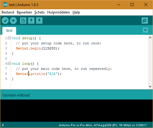
    But after saving the file I tried again, only reading rubbish. Thats strange! So it has something to do with saving the file and maybe setting a special encoding. Maybe thats related to the editor? Could you please try to redo what I explained and see if you get the same results? Thank you. @hek have you ever had such a problem of a sketch behaving differently after saving?


  • Mod

    @Anduril Ok, did some tests:

    Copied your problematic example string from this topic into Arduino IDE (1.6.5), on Windows 10:

    upload-d3f2ea5f-8442-4f01-9f16-d77ffc2c4b49

    Saved the sketch.

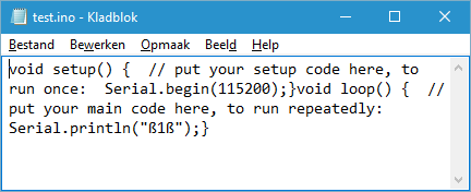
    Viewed sketch.ino in notepad:
    upload-65587bba-2f55-4d38-9071-303fa5df2772
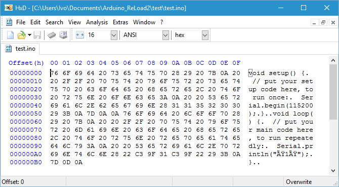
    Newlines are f*cked up, but "ß1ß" can clearly be recognized.

    Viewed the same sketch in HxD hex viewer:
    upload-d5300e08-17b9-4d7b-b069-dddba71f6649

    And there we are! The string is stored as Unicode characters!

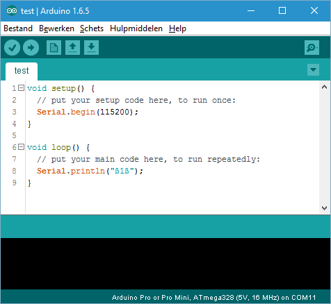
    Reading it back in Arduino IDE:
    upload-01fb9b7d-3b1d-40c5-8916-6a1da46913fa

    Everything looks fine again.

    Apparently the unicode string gets compiled directly and shows as multiple, wrong characters in your sketch when used/printed...

    Ok, one more idea: you can try to store the ß character as an escaped ASCII character in you string (refer to this ).
    This will look strange in the code, but should print correctly to the console:

    The ASCII escape sequence for ß is \xE1
    Your test sequence "ß1ß" then becomes "\xE11\xE1"
    

    Please try this...


  • @Yveaux
    hi
    there is problem for sensor library when we intend use the its examples as following
    In file included from \libraries\MySensors\MyGateway.cpp:13:0:

    \libraries\MySensors\utility/MsTimer2.h:7:2: error: #error MsTimer2 library only works on AVR architecture
    #error MsTimer2 library only works on AVR architecture
    ^
    In file included from \libraries\MySensors\MyGateway.cpp:14:0:
    \libraries\MySensors\utility/PinChangeInt.h:103:19: fatal error: new.h: No such file or directory
    #include <new.h>
    ^
    compilation terminated.
    Error compiling.


  • Mod

    @mkeyno did you change anything to the gateway code, and which version of MySensors are you running?
    I've ported the gateway code to ESP8266. That doesn't mean any sensor code will also automatically run on an ESP.
    Packaged with MySensors are a lot of libraries that will not compile on ESP, so if you try to use one (pinchange int or timers) it will likely fail to compile.


  • @Yveaux SUCCES!!! Thank you very much, your way worked nearly perfect. ONly small change: "ß" is represented by hexcode DF, so using \eDF gives the correct wifi password for me.
    Now a last thing as bonus: how to setup a fixed ip and not using dhcp? My dhcp is not very usable as it reassigns all IPs on reboot (stupid firmware by Deutsche Telekom).


  • Mod

    @Anduril Great to hear you got it to work!

    how to setup a fixed ip and not using dhcp?

    Google'd a bit. Seems like Wifi.config requires 3 parameters:

        // static ip, gateway, netmask
        WiFi.config(IPAddress(192,168,1,100), IPAddress(192,168,1,1), IPAddress(255,255,255,0));
    

    Make sure to call it after WiFi.begin().

    Btw. ESP8266 Arduino port follows the Arduino WiFi library API.


  • Admin

    You can set static ip in the dev-branch.


  • Mod

    @hek said:

    You can set static ip in the dev-branch.

    Even better 👍


  • @Yveaux no buddy I used the last update of your repository, my question is , are you aware that your esp8266 sample sketch call library that wont work with esp architecture? I've compare last update with previous library and I've find the for couple of header file following code has been added
    #ifdef AVR
    #include <avr/interrupt.h>
    #else
    #error MsTimer2 library only works on AVR architecture
    #endif

    and I was wondering why your sample sketch call such file into the compiling


  • Hi @Yveaux

    could you please assist in the error.

    ESP8266 MySensors Gateway
    Connecting to HoUsEoFcLoWnS
    scandone
    f 0, scandone
    .add 0
    aid 5
    pm open phy_2,type:2 0 0
    cnt 
    
    connected with HoUsEoFcLoWnS, channel 11
    dhcp client start...
    .ip:192.168.0.23,mask:255.255.255.0,gw:192.168.0.1
    .Connected!
    IP: 192.168.0.23
    
     ets Jan  8 2013,rst cause:4, boot mode:(3,7)
    
    wdt reset
    load 0x4010f000, len 1264, room 16 
    tail 0
    chksum 0x42
    csum 0x42
    ~ld


    The gateway just keeps looping and connecting.
    I'm using a NodeMCU with a NRF ( both from ebay),
    Using the Regular library, and default sketch with SSID/pass updated.

    i tried checking the error "rst cause:4, boot mode:(3,7)" but wasn't able to find something.

    I even tried to power it using a USB cellphone charger, but i was unable to telnet so that rules out the power issue

    Thanks in advance


  • update,
    the error changed to "rst cause:4, boot mode:(3,6)" once i added a capacitor.


  • Mod

    @D_dude said:

    These ESP's seem to walk in mysterious ways...
    A lot of people have them, running without any issues (including myself and hek) and some people can't seem to get them to run stable.
    On the net, a lot of stability/reset issues are are claimed to have a relation to power supply.

    I even tried to power it using a USB cellphone charger, but i was unable to telnet so that rules out the power issue

    There are a lot of assumptions in this sentence 😉
    What current rating is the cellphone charger? I'd advise one with at least 1amps, and a stable output.
    Not being able to telnet to the gateway can have more issues then just the ESP crashing...


  • @Yveaux
    Thank you for the response.

    As for the cell phone charger, I'm using a tablet charger Specifically original HP stream 7 charger, and it is able to provide more that 1amp. I Will try to use other charger/power supply to see if that helps.

    PS: I reloaded the gateway sketch and the error went back to boot mode (3,7) even with cap present.


  • Mod

    @D_dude I searched the net for a description of reset causes and boot modes but failed to find one.
    I have no clue of what they mean.


  • @Yveaux
    thank you for your assistance. I will try adding some debug in the code on the weekend to see what exactly is not running and possibly causing crash.


  • Mod

    I got a suggestion here to erase the flash before flashing. Haven't tried it yet, but it might help you @D_dude


  • @mfalkvidd
    Thank you, i will try this and post results.


  • @mfalkvidd
    tried erasing the flash using the method suggested but doesn't seem to be working for me. same result.
    Thanks for the tip though.


  • Mod

    Too bad. Thanks for posting your results.


  • here is my ESP8266 wifi gateway installed in wifi repeater box, taking the advantage that its has a 5 volts power supply.
    ESP8266WIFIgateway2.jpg ESP8266WIFIgateway1.jpg


  • Mod

    @luisgcu Nice housing!
    Thanks for the pics!


  • I'd been using the ESP gateway for several weeks, but recently was having trouble adding a new sensor I am developing.

    Since the copy of dev I built it with was now out of date, I went ahead and updated... still wasn't working right so while I had the serial link to it I checked and noticed it was crashing and cycling. It would work for hours, until I fired up my new node, then crash about immediately. A few dozen debug(PSTR())'s later, I found a cause.

    In core/MySensorsCore.cpp the result of _msg.getConfig() is dereferenced in a comparison, and it's possible it could return NULL ( like when it's a new node ). I put a check around that and it's not crashing anymore. Which is more than what I can say for my new sensor node....

    I have not tested this change with an AVR.

    I submitted PR 264.


  • Mod

    Great work @soward !


  • on some basic debugging, seems like my sketch is crashing in setupGateway.

    infact even adding a print statement, it only prints first 3 chars.

    My question is setupGateway takes output as an arg, which in turn is a function, should there be some parameters for this function?
    also "Serial.print(serialBuffer);" does not print anything i added prints above and before and they don't show up either.

      va_end (args);
      Serial.print("A1");
      Serial.print(serialBuffer);
      Serial.print("A2");
    

    any suggestions?


  • Mod

    @D_dude flush the serial output after each print.
    The ESP will output the serial data in the background while your programm continues and then it crashes.


  • Hi,
    I'm getting all the time this:

    ESP8266 MySensors Gateway
    Connecting to layla
    ......Connected!
    IP: 192.168.0.102
    0;0;3;0;9;gateway started, id=0, parent=0, distance=0

    Then it got stuck so I do reset and getting this in loop:

    ESP8266 MySensors Gateway
    Connecting to layla
    ..Connected!
    IP: 192.168.0.102
    0;0;3;0;9;radio init fail

    Soft WDT reset

    ctx: cont
    sp: 3ffefe70 end: 3fff00a0 offset: 01b0

    stack>>>
    3fff0020: 00000000 00000000 3ffeed74 40203665
    3fff0030: 0000007f 3ffef074 40205ba0 3ffef080
    3fff0040: 40202114 00000001 00000000 40205c10
    3fff0050: 6600a8c0 00ffffff 0100a8c0 3ffef074
    3fff0060: 3ffe84ac 3ffeee8c 3ffeefb0 4020256b
    3fff0070: 3ffe86b8 6600a8c0 00000000 00000000
    3fff0080: 3fffdc20 00000000 3ffef06d 40205bde
    3fff0090: 00000000 00000000 3ffef080 40100114
    <<<stack<<<

    ets Jan 8 2013,rst cause:2, boot mode:(3,6)

    load 0x4010f000, len 1264, room 16
    tail 0
    chksum 0x42
    csum 0x42
    ~ld


  • Mod

    @Yht 0;0;3;0;9;radio init fail
    Means there's something wrong with your nRF communication. The WDT reset following this is normal.


  • i have been using wifi gateway with Domoticz controller without any problems until recentely. After the last update to beta version of the controller, the gateway crashes when the controller request gateway version:
    Gateway startup complete.
    Client 0: 0;0;3;0;2;

    Exception (28):
    epc1=0x4000bf80 epc2=0x00000000 epc3=0x00000000 excvaddr=0x00000000 depc=0x00000000

    ctx: cont
    sp: 3ffebf60 end: 3ffec1f0 offset: 01a0

    I have tested with telnet client with the same request and it was ok. Then I saw that the request from controller was terminated with only <LF> and not with <CR><LF> and this is why it crashed. I have added the following to the sketch:

    •    if (inChar == '\n')
        {  
          if (inputString[i].string[inputString[i].idx-1] != '\r') { // if the last char is not CR then add it
          inputString[i].string[inputString[i].idx++]='\r';
         }
          // a command was issued by the client
          // we will now try to send it to the actuator
      

    and now it seems to work.
    Is this the right way to go?
    Thanks


  • Admin


  • @hek My code is from GatewayESP8266.ino example in Mysensors 1.5, line 234.


  • Admin

    Ok! Mis-read this line---

    After the last update to beta version....

    Thought you were talking about the development branch. Sorry.


  • Hi all,
    First, I have to say this is awsome what @Yveaux did, thank you!

    Sorry if this question takes you back in time. I don't know what channel and id to use for the nodes,I tried channel 97 and id from 1-5 but it is not working..
    are you using mesh lib?


  • Mod

    @Yht said:

    I don't know what channel and id to use for the nodes

    Just leave the default channel untouched for both sensors and gateway. It should be fine.
    The gateway will automatically be assigned ID 0, the nodes can have any fixed ID.
    Dynamic ID assignment requires some extra software, as the gateway does not support it.


  • I'm also seeing my ESP8266 gateway crash when the controller requests its version.

    I had not seen this thread so I started a new topic here: http://forum.mysensors.org/topic/2493/esp8266-wifi-gateway-crashes-and-reboots-when-controller-connects


  • Hardware Contributor


  • Mod

    @scalz Nice! Thanks for the link!


  • Just wanted to chime in and say thank you for this gateway script @Yveaux

    I originally had an ethernet gateway for the longest time. But when I changed over to an OnHub router, it stopped working because it doesn't like to handle static IP, and the current branch sketch is too large to enable DHCP. This worked wonderfully with the OnHub out of the box (ver 7390.62.2) and shows up with a hostname of ESP_DA7D8B.

    Thanks again!


  • Hi,
    When testing the ESP8266MQTTClient (downloaded latest version of the library today) and compiled with the NodeMCU 1.0 ...... option I get an odd result. The message at startup is (please disregard the "Radio init fail" - the radio was not yet connected. I just wanted to check the WiFi 😞

    2dO,4`lLMØl 8ðÿ0;0;3;0;9;Starting gateway (RNNGE-, 1.6.0-beta)
    0;0;3;0;9;Radio init failed. Check wiring.
    scandone
    state: 0 -> 2 (b0)
    state: 2 -> 3 (0)
    state: 3 -> 5 (10)
    add 0
    aid 2
    pm open phy_2,type:2 0 0
    cnt

    connected with XXXyyy, channel 1
    dhcp client start...
    ip:192.168.1.167,mask:255.255.255.0,gw:192.168.1.1

    I can see from the router that the connection to 192.168.1.167 is successful but the oddity is that I have set the gateway to use a static address and also connect to a SSID which is not XXXyyy. The defines are:

    // Enable MY_IP_ADDRESS here if you want a static ip address (no DHCP)
    #define MY_IP_ADDRESS 192,168,1,22
    // If using static ip you need to define Gateway and Subnet address as well
    #define MY_IP_GATEWAY_ADDRESS 192,168,1,1
    #define MY_IP_SUBNET_ADDRESS 255,255,255,0

    So the ESP8266 uses dhcp when it should have a static address and connects to a SSID which is not given but may have been previously used at earlier tests.

    I have looked at the code and tried a few changes to defines but none resulted in the override of dhcp.
    Anyone have a clue?


  • I have the exact hardware in this setup but can't even get to the point where the hardware is a problem! I'm having compile errors during verify that make no sense and that I can't seem to find in the forums using search:

    In file included from Esp8266Gateway.ino:69:0:
    C:\Users\xxxxx\Documents\Arduino\libraries\SPI/SPI.h:982:8: error: 'SPIClass' does not name a type
    extern SPIClass SPI;

    Any suggestions? I'm running windows 10 and Arduino 1.6.5 with the most current esp8266 board files through board manager.

    Apparently me and anything arduino related are like oil and water, yet I keep buying the stuff.


  • @bp_968 said:

    I have the exact hardware in this setup but can't even get to the point where the hardware is a problem! I'm having compile errors during verify that make no sense and that I can't seem to find in the forums using search:

    In file included from Esp8266Gateway.ino:69:0:
    C:\Users\xxxxx\Documents\Arduino\libraries\SPI/SPI.h:982:8: error: 'SPIClass' does not name a type
    extern SPIClass SPI;

    Any suggestions? I'm running windows 10 and Arduino 1.6.5 with the most current esp8266 board files through board manager.

    Apparently me and anything arduino related are like oil and water, yet I keep buying the stuff.

    I tried this on my laptop and it worked fine (the compile verify did anyway) so I'll be reinstalling the IDE and trying again and hopefully that resolves my issues!


  • Yesterday I have successfully installed the ESP8266 module and it works fine, but the Vera3 show something strange now.
    ESP.jpg
    Has anyone experienced this?


  • Mod

    @tjay4x4 Seems like to be an issue again when going from 8-bit to 32-bit architecture.
    Can you connect the ESP to your PC and capture the serial output when connecting to your lights and controlling them?


  • @Yveaux Thank you for reply. Here is the serial monitor.When I put 100% light it shows Ok. But 70% and others, shows some digitals. But all working fine! 🙂
    Insert Code Here

    .................Connected!
    
    0;0;3;0;9;gateway started, id=0, parent=0, distance=0
    0;0;3;0;9;read: 1-8-0 s=0,c=1,t=0,pt=7,l=5,sg=0:33.1
    1;0;1;0;0;33.1
    0;0;3;0;9;read: 1-8-0 s=1,c=1,t=0,pt=7,l=5,sg=0:44.2
    1;1;1;0;0;44.2
    0;0;3;0;9;read: 1-8-0 s=2,c=1,t=0,pt=7,l=5,sg=0:32.2
    1;2;1;0;0;32.2
    0;0;3;0;9;read: 1-8-0 s=1,c=1,t=0,pt=7,l=5,sg=0:44.3
    1;1;1;0;0;44.3
    Client 0 connected
    0;0;3;0;14;Gateway startup complete.
    Client 0 disconnected
    0;0;3;0;9;read: 9-8-0 s=4,c=1,t=0,pt=7,l=5,sg=0:27.0
    9;4;1;0;0;27.0
    0;0;3;0;9;read: 9-8-0 s=3,c=1,t=1,pt=7,l=5,sg=0:21.0
    9;3;1;0;1;21.0
    Client 0 connected
    0;0;3;0;14;Gateway startup complete.
    Client 0: 0;0;3;0;2;Get Version
    
    0;0;3;0;2;1.5.1
    Client 0: 11;0;1;1;3;1090519100
    
    0;0;3;0;9;send: 0-0-11-11 s=0,c=1,t=3,pt=0,l=10,sg=0,st=ok:1090519100
    0;0;3;0;9;read: 11-11-0 s=0,c=1,t=3,pt=0,l=10,sg=0:1090519100
    11;0;1;1;3;1090519100
    0;0;3;0;9;read: 11-11-0 s=0,c=1,t=2,pt=2,l=2,sg=0:805306369
    11;0;1;0;2;805306369
    0;0;3;0;9;read: 11-11-0 s=0,c=1,t=3,pt=2,l=2,sg=0:805306428
    11;0;1;0;3;805306428
    Client 0: 11;0;1;1;3;0
    
    0;0;3;0;9;send: 0-0-11-11 s=0,c=1,t=3,pt=0,l=1,sg=0,st=ok:0
    0;0;3;0;9;read: 11-11-0 s=0,c=1,t=3,pt=0,l=1,sg=0:0
    11;0;1;1;3;0
    0;0;3;0;9;read: 11-11-0 s=0,c=1,t=2,pt=2,l=2,sg=0:805306368
    11;0;1;0;2;805306368
    0;0;3;0;9;read: 11-11-0 s=0,c=1,t=3,pt=2,l=2,sg=0:805306368
    11;0;1;0;3;805306368
    Client 0: 11;0;1;1;3;100
    
    0;0;3;0;9;send: 0-0-11-11 s=0,c=1,t=3,pt=0,l=3,sg=0,st=ok:100
    0;0;3;0;9;read: 11-11-0 s=0,c=1,t=3,pt=0,l=3,sg=0:100
    11;0;1;1;3;100
    0;0;3;0;9;read: 11-11-0 s=0,c=1,t=2,pt=2,l=2,sg=0:1
    11;0;1;0;2;1
    0;0;3;0;9;read: 11-11-0 s=0,c=1,t=3,pt=2,l=2,sg=0:100
    11;0;1;0;3;100
    Client 0: 11;0;1;1;3;80
    
    0;0;3;0;9;send: 0-0-11-11 s=0,c=1,t=3,pt=0,l=2,sg=0,st=ok:80
    0;0;3;0;9;read: 11-11-0 s=0,c=1,t=3,pt=0,l=2,sg=0:80
    11;0;1;1;3;80
    0;0;3;0;9;read: 11-11-0 s=0,c=1,t=2,pt=2,l=2,sg=0:1
    11;0;1;0;2;1
    0;0;3;0;9;read: 11-11-0 s=0,c=1,t=3,pt=2,l=2,sg=0:80
    11;0;1;0;3;80
    0;0;3;0;9;read: 1-8-0 s=2,c=1,t=0,pt=7,l=5,sg=0:32.3
    1;2;1;0;0;32.3
    Client 0: 11;0;1;1;3;70
    
    0;0;3;0;9;send: 0-0-11-11 s=0,c=1,t=3,pt=0,l=2,sg=0,st=ok:70
    0;0;3;0;9;read: 11-11-0 s=0,c=1,t=3,pt=0,l=2,sg=0:70
    11;0;1;1;3;70
    0;0;3;0;9;read: 11-11-0 s=0,c=1,t=2,pt=2,l=2,sg=0:1107296257
    11;0;1;0;2;1107296257
    0;0;3;0;9;read: 11-11-0 s=0,c=1,t=3,pt=2,l=2,sg=0:1107296326
    11;0;1;0;3;1107296326
    Client 0: 11;0;1;1;3;1107296326
    
    0;0;3;0;9;send: 0-0-11-11 s=0,c=1,t=3,pt=0,l=10,sg=0,st=ok:1107296326
    0;0;3;0;9;read: 11-11-0 s=0,c=1,t=3,pt=0,l=10,sg=0:1107296326
    11;0;1;1;3;1107296326
    0;0;3;0;9;read: 11-11-0 s=0,c=1,t=2,pt=2,l=2,sg=0:922746881
    11;0;1;0;2;922746881
    0;0;3;0;9;read: 11-11-0 s=0,c=1,t=3,pt=2,l=2,sg=0:922746950
    11;0;1;0;3;922746950
    0;0;3;0;9;read: 9-8-0 s=3,c=1,t=1,pt=7,l=5,sg=0:20.0
    9;3;1;0;1;20.0
    Client 0: 11;0;1;1;3;922746950
    
    0;0;3;0;9;send: 0-0-11-11 s=0,c=1,t=3,pt=0,l=9,sg=0,st=ok:922746950
    0;0;3;0;9;read: 11-11-0 s=0,c=1,t=3,pt=0,l=9,sg=0:922746950
    11;0;1;1;3;922746950
    0;0;3;0;9;read: 11-11-0 s=0,c=1,t=2,pt=2,l=2,sg=0:922746881
    11;0;1;0;2;922746881
    0;0;3;0;9;read: 11-11-0 s=0,c=1,t=3,pt=2,l=2,sg=0:922746950
    11;0;1;0;3;922746950
    Client 0: 11;0;1;1;3;922746950
    
    0;0;3;0;9;send: 0-0-11-11 s=0,c=1,t=3,pt=0,l=9,sg=0,st=ok:922746950
    Client 0: 11;0;1;1;3;0
    
    0;0;3;0;9;send: 0-0-11-11 s=0,c=1,t=3,pt=0,l=1,sg=0,st=ok:0
    0;0;3;0;9;read: 11-11-0 s=0,c=1,t=3,pt=0,l=1,sg=0:0
    11;0;1;1;3;0
    0;0;3;0;9;read: 11-11-0 s=0,c=1,t=2,pt=2,l=2,sg=0:922746880
    11;0;1;0;2;922746880
    0;0;3;0;9;read: 11-11-0 s=0,c=1,t=3,pt=2,l=2,sg=0:922746880
    11;0;1;0;3;922746880
    Client 0: 11;0;1;1;3;100
    
    0;0;3;0;9;send: 0-0-11-11 s=0,c=1,t=3,pt=0,l=3,sg=0,st=ok:100
    0;0;3;0;9;read: 11-11-0 s=0,c=1,t=3,pt=0,l=3,sg=0:100
    11;0;1;1;3;100
    0;0;3;0;9;read: 11-11-0 s=0,c=1,t=2,pt=2,l=2,sg=0:1
    11;0;1;0;2;1
    0;0;3;0;9;read: 11-11-0 s=0,c=1,t=3,pt=2,l=2,sg=0:100
    11;0;1;0;3;100

  • Mod

    @tjay4x4 which version of MySensors are you running?


  • @Yveaux I use https://github.com/mysensors/Arduino/archive/master.zip
    Just reupload library
    Some additionl information.
    100%-90%-80%70%-60%-50%- OK 40%-bug 🙂
    10%-20%-30%-40% -OK 50%-bug

    ESP8266 MySensors Gateway
    Connecting to 1111
    ................Connected!
    IP: 192.168.1.44
    0;0;3;0;9;gateway started, id=0, parent=0, distance=0
    0;0;3;0;9;read: 9-8-0 s=3,c=1,t=1,pt=7,l=5,sg=0:20.0
    9;3;1;0;1;20.0
    0;0;3;0;9;read: 1-8-0 s=1,c=1,t=0,pt=7,l=5,sg=0:44.5
    1;1;1;0;0;44.5
    Client 0 connected
    0;0;3;0;14;Gateway startup complete.
    Client 0: 0;0;3;0;2;Get Version
    
    0;0;3;0;2;1.5.1
    Client 0: 11;0;1;1;3;0
    
    0;0;3;0;9;send: 0-0-11-11 s=0,c=1,t=3,pt=0,l=1,sg=0,st=ok:0
    0;0;3;0;9;read: 11-11-0 s=0,c=1,t=3,pt=0,l=1,sg=0:0
    11;0;1;1;3;0
    0;0;3;0;9;read: 11-11-0 s=0,c=1,t=2,pt=2,l=2,sg=0:536870912
    11;0;1;0;2;536870912
    0;0;3;0;9;read: 11-11-0 s=0,c=1,t=3,pt=2,l=2,sg=0:536870912
    11;0;1;0;3;536870912
    Client 0: 11;0;1;1;3;100
    
    0;0;3;0;9;send: 0-0-11-11 s=0,c=1,t=3,pt=0,l=3,sg=0,st=ok:100
    0;0;3;0;9;read: 11-11-0 s=0,c=1,t=3,pt=0,l=3,sg=0:100
    11;0;1;1;3;100
    0;0;3;0;9;read: 11-11-0 s=0,c=1,t=2,pt=2,l=2,sg=0:1
    11;0;1;0;2;1
    0;0;3;0;9;read: 11-11-0 s=0,c=1,t=3,pt=2,l=2,sg=0:100
    11;0;1;0;3;100
    Client 0: 11;0;1;1;3;80
    
    0;0;3;0;9;send: 0-0-11-11 s=0,c=1,t=3,pt=0,l=2,sg=0,st=ok:80
    0;0;3;0;9;read: 11-11-0 s=0,c=1,t=3,pt=0,l=2,sg=0:80
    11;0;1;1;3;80
    0;0;3;0;9;read: 11-11-0 s=0,c=1,t=2,pt=2,l=2,sg=0:1
    11;0;1;0;2;1
    0;0;3;0;9;read: 11-11-0 s=0,c=1,t=3,pt=2,l=2,sg=0:80
    11;0;1;0;3;80
    Client 0: 11;0;1;1;3;70
    
    0;0;3;0;9;send: 0-0-11-11 s=0,c=1,t=3,pt=0,l=2,sg=0,st=ok:70
    0;0;3;0;9;read: 11-11-0 s=0,c=1,t=3,pt=0,l=2,sg=0:70
    11;0;1;1;3;70
    0;0;3;0;9;read: 11-11-0 s=0,c=1,t=2,pt=2,l=2,sg=0:1
    11;0;1;0;2;1
    0;0;3;0;9;read: 11-11-0 s=0,c=1,t=3,pt=2,l=2,sg=0:70
    11;0;1;0;3;70
    Client 0: 11;0;1;1;3;60
    
    0;0;3;0;9;send: 0-0-11-11 s=0,c=1,t=3,pt=0,l=2,sg=0,st=ok:60
    0;0;3;0;9;read: 11-11-0 s=0,c=1,t=3,pt=0,l=2,sg=0:60
    11;0;1;1;3;60
    0;0;3;0;9;read: 11-11-0 s=0,c=1,t=2,pt=2,l=2,sg=0:1
    11;0;1;0;2;1
    0;0;3;0;9;read: 11-11-0 s=0,c=1,t=3,pt=2,l=2,sg=0:60
    11;0;1;0;3;60
    0;0;3;0;9;read: 1-8-0 s=1,c=1,t=0,pt=7,l=5,sg=0:44.6
    1;1;1;0;0;44.6
    Client 0: 11;0;1;1;3;50
    
    0;0;3;0;9;send: 0-0-11-11 s=0,c=1,t=3,pt=0,l=2,sg=0,st=ok:50
    0;0;3;0;9;read: 11-11-0 s=0,c=1,t=3,pt=0,l=2,sg=0:50
    11;0;1;1;3;50
    0;0;3;0;9;read: 11-11-0 s=0,c=1,t=2,pt=2,l=2,sg=0:1107296257
    11;0;1;0;2;1107296257
    0;0;3;0;9;read: 11-11-0 s=0,c=1,t=3,pt=2,l=2,sg=0:1107296306
    11;0;1;0;3;1107296306
    0;0;3;0;9;read: 7-5-0 s=0,c=1,t=0,pt=7,l=5,sg=0:30.7
    7;0;1;0;0;30.7
    0;0;3;0;9;read: 3-2-0 s=0,c=1,t=0,pt=7,l=5,sg=0:30.2
    3;0;1;0;0;30.2
    0;0;3;0;9;read: 7-5-0 s=0,c=1,t=0,pt=7,l=5,sg=0:30.6
    7;0;1;0;0;30.6
    0;0;3;0;9;read: 3-2-0 s=0,c=1,t=0,pt=7,l=5,sg=0:30.1
    3;0;1;0;0;30.1
    0;0;3;0;9;read: 1-8-0 s=1,c=1,t=0,pt=7,l=5,sg=0:44.5
    1;1;1;0;0;44.5
    Client 0: 11;0;1;1;3;0
    
    0;0;3;0;9;send: 0-0-11-11 s=0,c=1,t=3,pt=0,l=1,sg=0,st=ok:0
    0;0;3;0;9;read: 11-11-0 s=0,c=1,t=3,pt=0,l=1,sg=0:0
    11;0;1;1;3;0
    0;0;3;0;9;read: 11-11-0 s=0,c=1,t=2,pt=2,l=2,sg=0:1107296256
    11;0;1;0;2;1107296256
    0;0;3;0;9;read: 11-11-0 s=0,c=1,t=3,pt=2,l=2,sg=0:1107296256
    11;0;1;0;3;1107296256
    Client 0: 11;0;1;1;3;100
    
    0;0;3;0;9;send: 0-0-11-11 s=0,c=1,t=3,pt=0,l=3,sg=0,st=ok:100
    0;0;3;0;9;read: 11-11-0 s=0,c=1,t=3,pt=0,l=3,sg=0:100
    11;0;1;1;3;100
    0;0;3;0;9;read: 11-11-0 s=0,c=1,t=2,pt=2,l=2,sg=0:1
    11;0;1;0;2;1
    0;0;3;0;9;read: 11-11-0 s=0,c=1,t=3,pt=2,l=2,sg=0:100
    11;0;1;0;3;100
    Client 0: 11;0;1;1;3;0
    
    0;0;3;0;9;send: 0-0-11-11 s=0,c=1,t=3,pt=0,l=1,sg=0,st=ok:0
    0;0;3;0;9;read: 11-11-0 s=0,c=1,t=3,pt=0,l=1,sg=0:0
    11;0;1;1;3;0
    0;0;3;0;9;read: 11-11-0 s=0,c=1,t=2,pt=2,l=2,sg=0:0
    11;0;1;0;2;0
    0;0;3;0;9;read: 11-11-0 s=0,c=1,t=3,pt=2,l=2,sg=0:0
    11;0;1;0;3;0
    Client 0: 11;0;1;1;3;10
    
    0;0;3;0;9;send: 0-0-11-11 s=0,c=1,t=3,pt=0,l=2,sg=0,st=ok:10
    0;0;3;0;9;read: 11-11-0 s=0,c=1,t=3,pt=0,l=2,sg=0:10
    11;0;1;1;3;10
    0;0;3;0;9;read: 11-11-0 s=0,c=1,t=2,pt=2,l=2,sg=0:1
    11;0;1;0;2;1
    0;0;3;0;9;read: 11-11-0 s=0,c=1,t=3,pt=2,l=2,sg=0:10
    11;0;1;0;3;10
    Client 0: 11;0;1;1;3;20
    
    0;0;3;0;9;send: 0-0-11-11 s=0,c=1,t=3,pt=0,l=2,sg=0,st=ok:20
    0;0;3;0;9;read: 11-11-0 s=0,c=1,t=3,pt=0,l=2,sg=0:20
    11;0;1;1;3;20
    0;0;3;0;9;read: 11-11-0 s=0,c=1,t=2,pt=2,l=2,sg=0:1
    11;0;1;0;2;1
    0;0;3;0;9;read: 11-11-0 s=0,c=1,t=3,pt=2,l=2,sg=0:20
    11;0;1;0;3;20
    Client 0: 11;0;1;1;3;30
    
    0;0;3;0;9;send: 0-0-11-11 s=0,c=1,t=3,pt=0,l=2,sg=0,st=ok:30
    0;0;3;0;9;read: 11-11-0 s=0,c=1,t=3,pt=0,l=2,sg=0:30
    11;0;1;1;3;30
    0;0;3;0;9;read: 11-11-0 s=0,c=1,t=2,pt=2,l=2,sg=0:1
    11;0;1;0;2;1
    0;0;3;0;9;read: 11-11-0 s=0,c=1,t=3,pt=2,l=2,sg=0:30
    11;0;1;0;3;30
    0;0;3;0;9;read: 1-8-0 s=1,c=1,t=0,pt=7,l=5,sg=0:44.6
    1;1;1;0;0;44.6
    Client 0: 11;0;1;1;3;40
    
    0;0;3;0;9;send: 0-0-11-11 s=0,c=1,t=3,pt=0,l=2,sg=0,st=ok:40
    0;0;3;0;9;read: 11-11-0 s=0,c=1,t=3,pt=0,l=2,sg=0:40
    11;0;1;1;3;40
    0;0;3;0;9;read: 11-11-0 s=0,c=1,t=2,pt=2,l=2,sg=0:1107296257
    11;0;1;0;2;1107296257
    0;0;3;0;9;read: 11-11-0 s=0,c=1,t=3,pt=2,l=2,sg=0:1107296296
    11;0;1;0;3;1107296296
    Client 0: 11;0;1;1;3;100
    
    0;0;3;0;9;send: 0-0-11-11 s=0,c=1,t=3,pt=0,l=3,sg=0,st=ok:100
    0;0;3;0;9;read: 11-11-0 s=0,c=1,t=3,pt=0,l=3,sg=0:100
    11;0;1;1;3;100
    0;0;3;0;9;read: 11-11-0 s=0,c=1,t=2,pt=2,l=2,sg=0:1
    11;0;1;0;2;1
    0;0;3;0;9;read: 11-11-0 s=0,c=1,t=3,pt=2,l=2,sg=0:100
    11;0;1;0;3;100
    Client 0: 11;0;1;1;3;0
    
    0;0;3;0;9;send: 0-0-11-11 s=0,c=1,t=3,pt=0,l=1,sg=0,st=ok:0
    0;0;3;0;9;read: 11-11-0 s=0,c=1,t=3,pt=0,l=1,sg=0:0
    11;0;1;1;3;0
    0;0;3;0;9;read: 11-11-0 s=0,c=1,t=2,pt=2,l=2,sg=0:0
    11;0;1;0;2;0
    0;0;3;0;9;read: 11-11-0 s=0,c=1,t=3,pt=2,l=2,sg=0:0
    11;0;1;0;3;0
    0;0;3;0;9;read: 7-5-0 s=0,c=1,t=0,pt=7,l=5,sg=0:30.7
    7;0;1;0;0;30.7
    0;0;3;0;9;read: 1-8-0 s=1,c=1,t=0,pt=7,l=5,sg=0:44.5
    1;1;1;0;0;44.5
    0;0;3;0;9;read: 9-8-0 s=3,c=1,t=1,pt=7,l=5,sg=0:21.0
    9;3;1;0;1;21.0
    0;0;3;0;9;read: 3-2-0 s=0,c=1,t=0,pt=7,l=5,sg=0:30.2
    3;0;1;0;0;30.2
    0;0;3;0;9;read: 1-8-0 s=0,c=1,t=0,pt=7,l=5,sg=0:33.4
    1;0;1;0;0;33.4
    0;0;3;0;9;read: 9-8-0 s=3,c=1,t=1,pt=7,l=5,sg=0:20.0
    9;3;1;0;1;20.0


  • @Yveaux Now everything working! I reinstall all "Arduino-master" to Arduino 1.6 folder and now ALL Ok. Sorry for disturb. Thank you!!!


  • Mod

    @tjay4x4 try development version of MySensors. This thread discussions a similar issue:
    http://forum.mysensors.org/topic/2118/esp8266-wifi-gateway-issue/2


  • Mod

    @tjay4x4 Just crossed my reply! Great it's working now!


  • Yesterday I switched gateway hardware from serial gateway based on arduino pro mini 3.3V and nrf24l01+ (connected directly to uart port of my mikrotik router) to esp8266 nodemcu and nrf24l01+ (exactly as at this page: http://www.mysensors.org/build/esp8266_gateway, using GatewayESP8266 sketch from 1.6 branch, revision https://github.com/mysensors/Arduino/tree/1035f84a431a8f591d31100c3e73e99a8245e345).

    I have 4 nodes with ~27 sensors total, half of sensors sending data every 10 seconds, another sensors send data only if environment changed.

    After switching to esp8266 my gateway started loosing packets (messages) from my sensor nodes:
    mysensors_esp8266.png
    Left side of graphs is esp8266, right side is old pro mini serial gateway, sensors sending data every 10 seconds. Distance between gateways is about 5-10 centimeters. Both nrf24l01+ boards oriented in the same direction.

    nrf24l01+ board isn't changed at all (I'm using old board from pro mini serial gateway).

    Also, I have tried different nrf24l01+ boards (different PCBs and different chip revisions, but seems like all of them are fake china chips). I have tried soldering 220 uF electrolytic and 0.1 uF ceramic capacitors directly to nrf24l01+ power pins. But nothing changed. Esp8266 gateway is losing messages.

    Switching back to pro mini serial gateway is completely solves issue (as shown in graph above).

    What else can I try to fix this? Could it be interference between wifi chip and nrf24? Or, maybe, this is software problem? Maybe non-interrupt driven polling of nrf24l01 causes loosing messages coming too often?


  • Admin

    @robosensor

    Interesting graph... But I have no immediate answer to you.


  • @hek graphs are drawn by Zabbix. My own Perl script connects directly to gateway, reads sensor data and sends this data directly to Zabbix.

    Also, I have tried to write raw data from gateway directly to file and execute "tail -f logfile.txt | grep sensor-specific-id". With old pro mini gateway data from sensor comes every 10 seconds. From esp8266 gateway sensor data comes very irregular.

    Also, every send() call in all my nodes followed by wait(25) call to reduce possible power issues and interference issues.

    UPDATE: I have recompiled esp8266-gateway sketch with debugging enabled, but I get the same results with loosing messages then I connecting directly to uart port of esp8266 uart-usb converter.


  • Mod

    @robosensor What strikes me is the fact that most of the time not all sensor values seem to disappear at the same time. A failing WiFi connection would be the most likely cause when all dis/reappear at the same time (like at 13:44 and 13:22).
    However, most of the time at least one sensor seems to report its values correctly. IMO This rules out the radio.
    Is there anything interesting in the serial logs?


  • @Yveaux thank you for your reply. It is not failing wifi connection, as the same problem exists then I using serial connection to esp8266 (via on-board usb-uart converter on nodemcu board).

    Nothing interesting in the serial logs (with debug mode enabled), just random absence of sensor data. Seems like I should connect sensor node to collect debug logs from node side.

    Also speed is changed - much faster CPU (80 MHz vs 8 MHz) and much faster connection (wifi vs uart 9600 bps). Maybe this affects.


  • Seems like problem with loosing messages is gateway firmware related.

    Then I connect two controllers (my own perl script and MYSController 0.1.2.282) to esp8266 gateway (#define MY_GATEWAY_MAX_CLIENTS 2), both controllers receiving exactly the same data from gateway, but messages lost even more.

    mysensors_esp8266_two_controllers.png

    1 on graphs = one controller connected
    2 on graphs = two controllers connected.

    I'm not familiar with esp8266 network programming, but could it be that firmware looses incoming packets from nrf24l01+ due to blocking call to wifi-related network functions? Seems like during sending data to wifi network firmware does not have time to pick up all incoming packets from nrf24l01+ chip.


  • I think I found problem. As I said before, seems like WiFi's clients[i].write() call blocks thread for a very long time.

    I added logging of write() time:

    		// Send message to connected clients
    		#if defined(MY_GATEWAY_ESP8266)
    			unsigned long start_time = hwMillis();
    			for (uint8_t i = 0; i < ARRAY_SIZE(clients); i++)
    			{
    				if (clients[i] && clients[i].connected())
    				{
    					clients[i].write((uint8_t*)_ethernetMsg, strlen(_ethernetMsg));
    				}
    			}
    			debug(PSTR("WiFi transaction time: %u ms\n"), hwMillis() - start_time);
    		#else
    			_ethernetServer.write(_ethernetMsg);
    		#endif
    

    And got following results:
    For Perl script from FreeBSD server in another country (ping to server is about 55 milliseconds):

    0;0;3;0;9;WiFi transaction time: 141 ms
    0;0;3;0;9;read: 2-2-0 s=1,c=1,t=23,pt=2,l=2,sg=0:98
    0;0;3;0;9;WiFi transaction time: 141 ms
    0;0;3;0;9;read: 2-2-0 s=6,c=1,t=43,pt=3,l=2,sg=0:2
    0;0;3;0;9;WiFi transaction time: 140 ms
    0;0;3;0;9;read: 1-1-0 s=105,c=1,t=0,pt=7,l=5,sg=0:27.5000
    0;0;3;0;9;WiFi transaction time: 136 ms
    0;0;3;0;9;read: 1-1-0 s=106,c=1,t=0,pt=7,l=5,sg=0:52.8750
    0;0;3;0;9;WiFi transaction time: 140 ms
    0;0;3;0;9;read: 1-1-0 s=107,c=1,t=0,pt=7,l=5,sg=0:45.9375
    0;0;3;0;9;WiFi transaction time: 142 ms
    0;0;3;0;9;read: 1-1-0 s=108,c=1,t=0,pt=7,l=5,sg=0:34.4375
    0;0;3;0;9;WiFi transaction time: 137 ms
    0;0;3;0;9;read: 1-1-0 s=1,c=1,t=16,pt=0,l=1,sg=0:0
    0;0;3;0;9;WiFi transaction time: 143 ms
    

    Connection from LAN (windows telnet client):

    0;0;3;0;9;read: 3-3-0 s=1,c=1,t=23,pt=2,l=2,sg=0:61
    0;0;3;0;9;WiFi transaction time: 209 ms
    0;0;3;0;9;read: 4-4-0 s=1,c=1,t=24,pt=2,l=2,sg=0:152
    0;0;3;0;9;WiFi transaction time: 201 ms
    0;0;3;0;9;read: 4-4-0 s=2,c=1,t=24,pt=2,l=2,sg=0:43
    0;0;3;0;9;WiFi transaction time: 212 ms
    0;0;3;0;9;read: 4-4-0 s=3,c=1,t=24,pt=2,l=2,sg=0:129
    0;0;3;0;9;WiFi transaction time: 209 ms
    0;0;3;0;9;read: 4-4-0 s=4,c=1,t=24,pt=2,l=2,sg=0:147
    0;0;3;0;9;WiFi transaction time: 208 ms
    0;0;3;0;9;read: 2-2-0 s=102,c=1,t=0,pt=7,l=5,sg=0:4.2500
    0;0;3;0;9;WiFi transaction time: 221 ms
    0;0;3;0;9;read: 2-2-0 s=103,c=1,t=0,pt=7,l=5,sg=0:27.4375
    0;0;3;0;9;WiFi transaction time: 208 ms
    0;0;3;0;9;read: 2-2-0 s=104,c=1,t=0,pt=7,l=5,sg=0:23.3750
    0;0;3;0;9;WiFi transaction time: 210 ms
    0;0;3;0;9;read: 2-2-0 s=3,c=1,t=1,pt=7,l=5,sg=0:99.9
    0;0;3;0;9;WiFi transaction time: 208 ms
    

    Seems like many packets coming to NRF24L01+ in this time interval (140-200 milliseconds) and this causes NRF buffer overflow and packet loss.


Log in to reply
 

Suggested Topics

0
Online

11.2k
Users

11.1k
Topics

112.5k
Posts