My own board (50mm x 30mm)
-
Hi GertSanders,
After ordered and make 3 of 50mm x 30mm board with success. Now I ordered the AC Capable 50mm x 50mm board. I try to read the schema and I have some question. If I want to use this board with only 2 AAA battery, Do I need to use AMS1117? and witch jumper do I need to close? It is optional to use AT24C ?
Thank you for your help
-
@Carl-H To use the board with AA batteries you do NOT need to place the AMS1117. But you will need to short the jumper "BAT" which you will find on the same surface as the AMS1117 if you want to feed the NRF24 with the same power.
The batteries are connected to the Vcc power line. The NRF24 is connected to the 3V3 power line. There is no interconnection, unless you use the AMS1117 or you short the jumper "BAT".The AT24C's are optional. If you do plan to use them, you will also need to place the I2C pull resistors and you will need to short the jumpers RSCL and RSDA. These two jumpers connect the pull-up resistors to the SCL and SDA lines.
If you use a sensor connected to the pins SCL/SDA of the extension connector you sometimes have no need for pull-ups as the sensor itself has them.
The jumpers SCL-SDA and SDA-SCL are there to allow switching the signals of the SCL/SDA pins on the extension connector. The jumper closest to the board edge is for the pin on the very edge of the connector, the jumper close to the ATSHA is for the second pin. Without shorting these two jumpers, the pins on the extension connector have no function.
Some sensor-boards have a SDA-SCL-GND-3V3 connector, others have a SCL-SDA-GND-3V3 pattern. The jumpers are there to be able to use both types.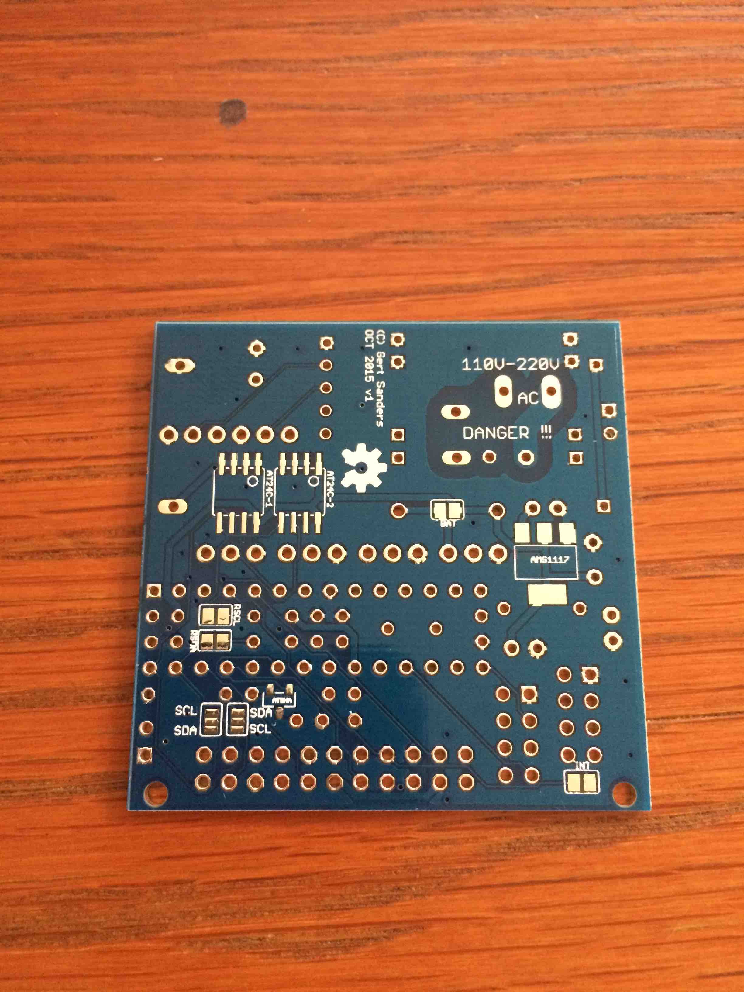
-
@Carl-H It is part of the expansion connector.
I added more info on the OpenHardware.io site.
-
Ok my boards arrived from DirtyPCB.
A couple of questions:-1.I am not using NR2 (The radio socket that protrudes),Also i am using the internal osc and not the xtal.
So can i leave out C9,NR2 Socket,C5,C6,Xtal ?
2.What are C2,C3 doing.
The socket for the cpu i have fitted will not let me squeeze them in.Should i solder them in underneath or can they be left out?
-
@mtucker
-
Yes you are right about leaving out these components, but if you use NR1 i should leave out C8 and keep C9 (mount the decouple C's as close to the decouple component as possible)
-
these components are for decoupling the uP. You can mount them at the bottom, do not leave the out.
I used a tip from earlier in this forum thread for gaining a little bit more space when using these
Cheerz
-
-
@BartE answered perfectly. You can leave out C5,C6 and XTAL if you use the internal oscillator. C9 is for the NRF24, no matter if you use NR1 or nR2 socket. And yes, you only need 1 socket, so if you use NR1, no need to add NR2 (and vice versa).
Socket NR2 is for the longer (and power amplified) radio with external antenna, NR1 was intended for the standard NRF24L01+ with PCB antenna.
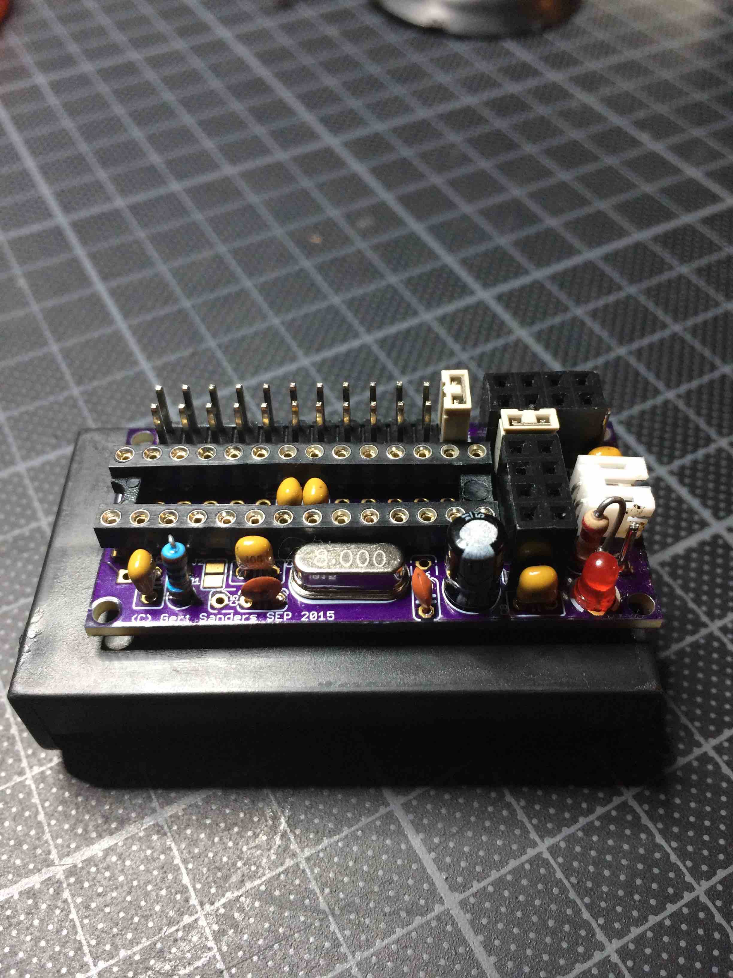
C2 decouples AVCC (the analog power input), just as C1 decouples the VCC (digital) power input. C3 stabilises the analog reference input. If you do not use the analog->digital conversion, you could skip C3 as well.I also do not use standard 28 pin sockets, but strip sockets just like BartE.
In the image here I used a standard socket, but cut away the middle "bridge" to allow mounting the decoupling capacitors.https://www.openhardware.io/uploads/568faa0cbaba42246aa57103/image/IMG_7527.jpg
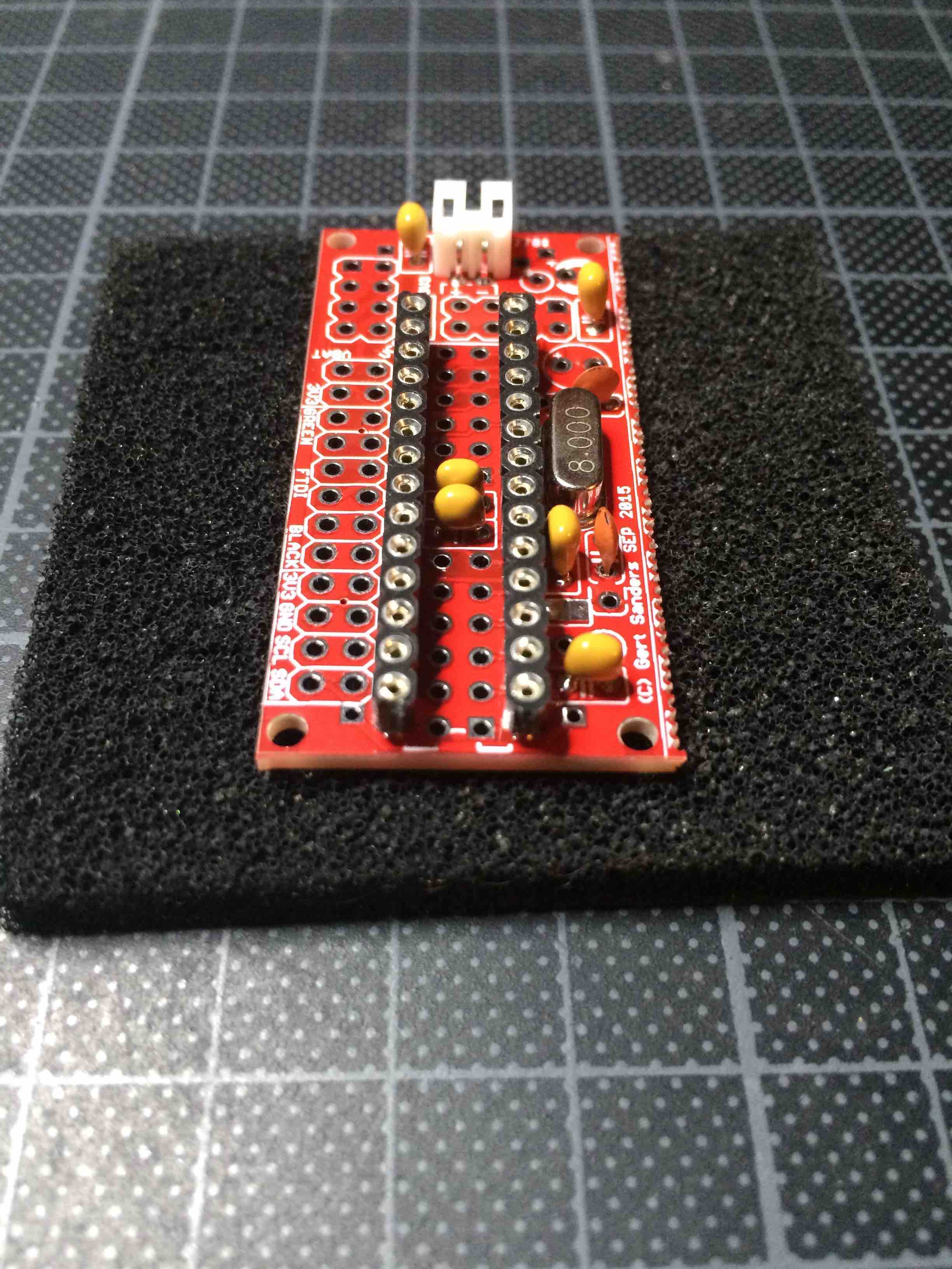
In the image below I use the strips BartE mentioned:
https://www.openhardware.io/uploads/568faa0cbaba42246aa57103/image/IMG_7686.jpg
More images and details are here:
https://www.openhardware.io/view/5/Battery-based-atmega328p-sensor-no-SMD
-
I am pulling out what hair i have left.
All i am getting is this:-
find parent
send: 253-253-255-255 s=255,c=3,t=7,pt=0,l=0,sg=0,st=bc:
find parent
send: 253-253-255-255 s=255,c=3,t=7,pt=0,l=0,sg=0,st=bc:
find parent
send: 253-253-255-255 s=255,c=3,t=7,pt=0,l=0,sg=0,st=bc:
find parent
send: 253-253-255-255 s=255,c=3,t=7,pt=0,l=0,sg=0,st=bc:
find parent
send: 253-253-255-255 s=255,c=3,t=7,pt=0,l=0,sg=0,st=bc:
find parent
send: 253-253-255-255 s=255,c=3,t=7,pt=0,l=0,sg=0,st=bc:
Init complete, id=253, parent=255, distance=255
Battery:3.161 Batt%:90 Temperature:21.73C Humidity:56%
find parent
send: 253-253-255-255 s=255,c=3,t=7,pt=0,l=0,sg=0,st=bc: -
Node 253 tries to connect and fint its way to the gateway (find parent) but doesnt get any respons.
Do you have a working gateway - what does the gateway log looks like? -
Which controller are you using?
-
@GertSanders
I have been struggling to upload photos in the openhardware section of your node and I think it is better if we move our discussion here. Take a look at these: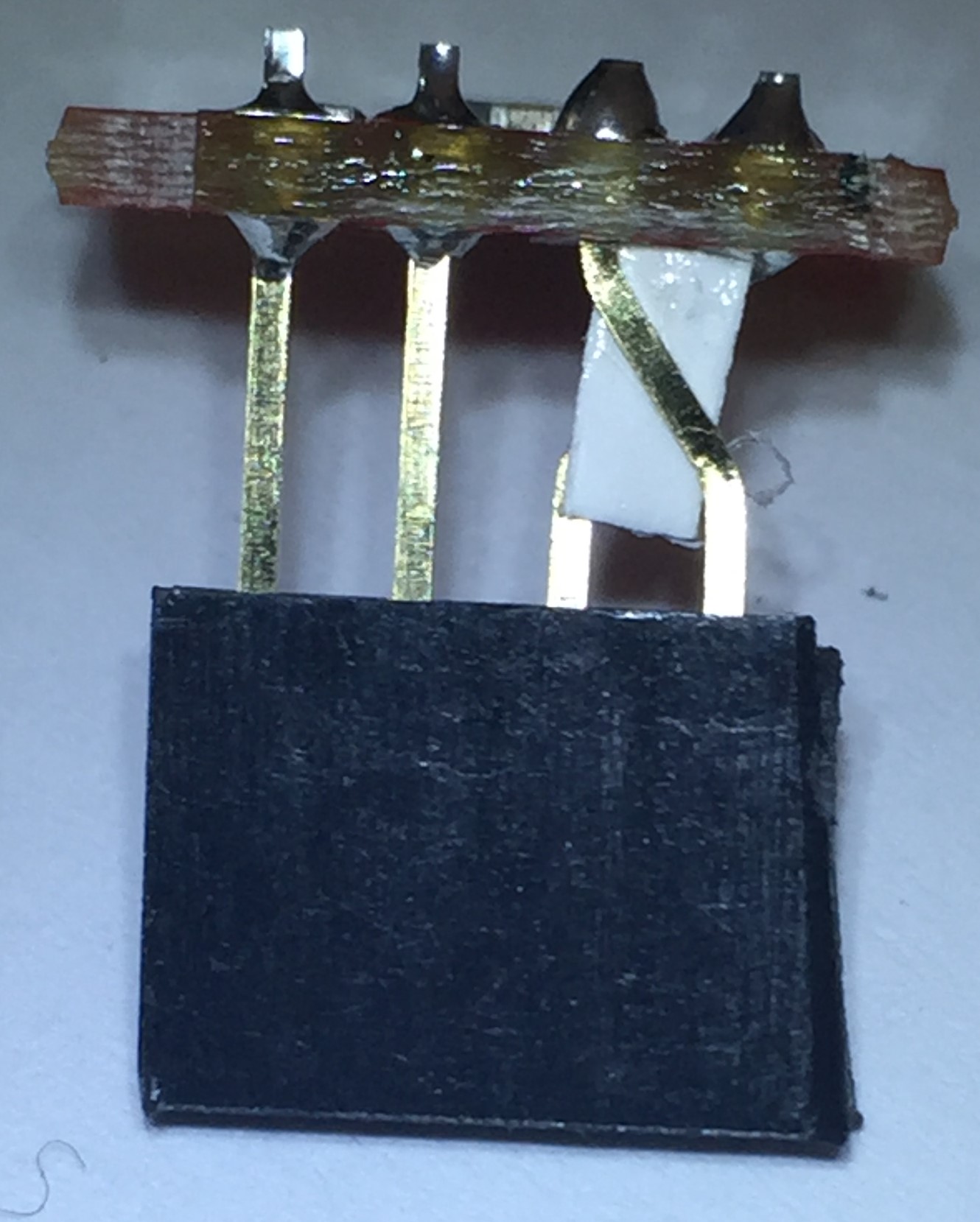
This is my answer to the problem, but I think we can have a neater solution by having jumpers deciding on SDA/SDL pin out ?
-
@GertSanders
I have been struggling to upload photos in the openhardware section of your node and I think it is better if we move our discussion here. Take a look at these:This is my answer to the problem, but I think we can have a neater solution by having jumpers deciding on SDA/SDL pin out ?
@alexsh1 There is indeed a better solution, the next version of this board will allow swapping the I2C data and clock pins :-)
-
@alexsh1 There is indeed a better solution, the next version of this board will allow swapping the I2C data and clock pins :-)
@GertSanders
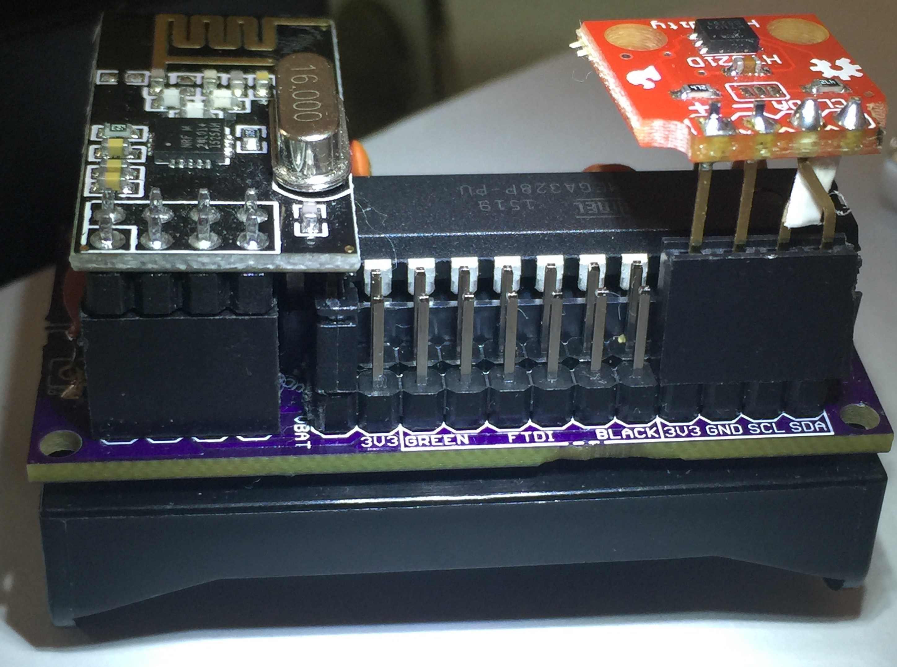
Other than that I have not been using the JST connector - this may save some space unless you want to leave it as a power backup. I never used the second row pins (behind the FTDI connection) and some of them are not accessible if using a sensor connected via I2C. -
@gloob There are two connections on the board to allow soldering the battery holder. Both the AA and AAA versions I use have the same pin spacing (seems standard), so you can use an AA battery holder as @alexsh1 does, or an AAA as I have.
http://forum.mysensors.org/uploads/files/1446751714416-image.jpeg
The red arrows show where the batteryholder pins should go. If you have individual AAA battery holders, then the pins surrounded by yellow circle are also used to connect the batteries in series. If the battery holder holds 2 batteries, then only the pins pointed to by red arrows are used.
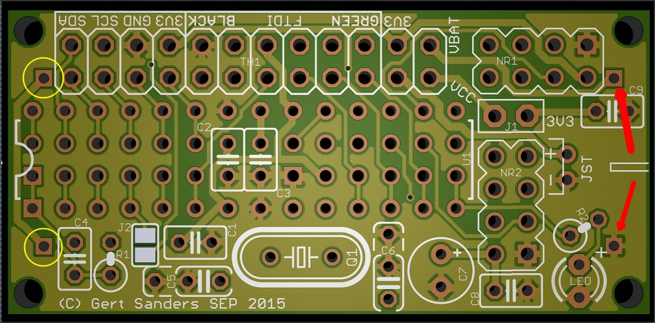
The PLUS sign next the the pin on the lower right of the above image is for the LED, the polarity of the pins from the battery is marked on the silkscreen of the bottom side. Looking at it from the top side, the pin above right is for Positive, the pin on below right is for Negative (or GND).
Jumper J2 is to connect the IRQ pin from the NRF24 to pin 2 (INT0) of the atmega328. You could also use that to connect a switch between the top jumper pad (connected to pin 2) and the extra ground pin of C5, to use with a doorswitch. I have used this with the internal pull up, but that would not be very good for the battery-use. It is better to use a 1MOhm pull up resistor wich can also be connected using the extra hole connected to pin 2 and Vcc
-
@alexsh1 There is indeed a better solution, the next version of this board will allow swapping the I2C data and clock pins :-)
@GertSanders
I have been running these boards for some time now and overall very easy and compact.
And battery life on 2 AA batteries is years.
But i still have problems with deadspots in the house etc.
So i thought i would try changing the radio's to rfm69w and make another serial gateway with an rfm69hw.
I have received some of the hallard nrf to rfm adapter boards which i believe can be plugged straight in
What i would like to know is,Would it be ok to use one of these boards as a serial gateway with an ftdi adapter?
I am using the board barebones with no external crystal etc at 8mhz.(would this be a problem for a gateway?).This would save on a lot of wiring (Level shifters etc).