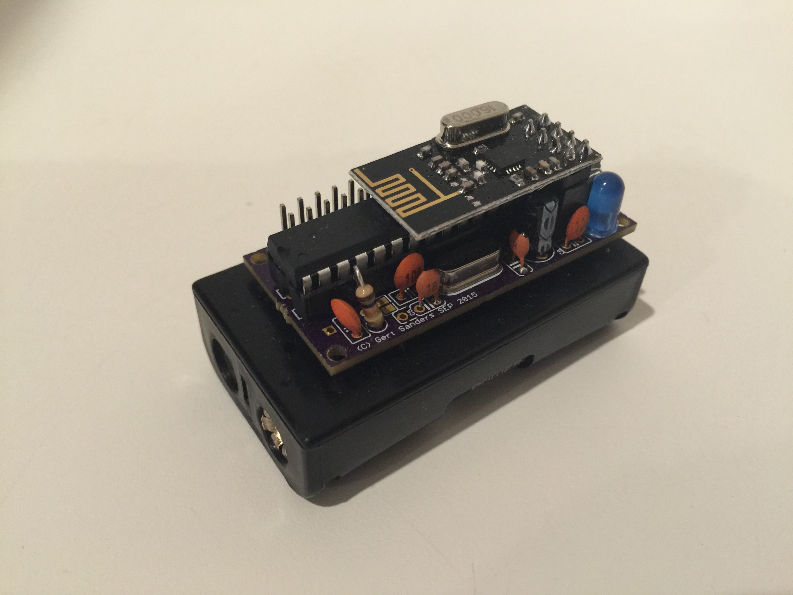
My own board (50mm x 30mm)
-
@GertSanders
Thanks for your support. I have now the serial gateway sketch running and output of the arduino seems good:0;0;3;0;9;gateway started, id=0, parent=0, distance=0 0;0;3;0;14;Gateway startup complete.I will now order some Si7021 sensors and continue my testing.
Can I use the following sensors:
Si7021 Industrial High Precision Humidity Sensor I2C Interface for Arduino
-
@gloob I'm using the same sensors for Temperature and Humidity. The pinout of these boards is what I based my pinout on my red board on. (3V3, GND, SCL, SDA). I'm using now 5 of these.
-
Ok, after a few long days I managed to burn the bootloader. For those who are struggling with the same problem please note the following:
- Use Nick Gammon's website and optiboot bootloader (512kb only). I had a standard ATmegaBOOT_168_atmega328_pro_8MHz_hex (Lilypad 8 MHz loader) and could not make it work with 3.3.v.
- Important: the 2048kb bootloader's (Lilypad 8MHz) address is 0x7800. For the optiboot (512Kb) you need to change it for 0x7E00. Now everything works fine - I just need now to change fuses to make sure the voltage can go down below 2V.
@GertSanders I wonder what sketches do you use with this board? it is nice to have Si7021 (it is pin-for-pin for your board) for temp and humidity.
-
@alexsh1 I make my own sketches, the one for my board with SI7021 is used most in my house. I also have a repeater, a GSM node, a sleeper node which wakes up when switches are tripped (basis for upcoming door sensor node). I work with the development version of the library (1.6.0-beta) of Mysensors
I added my Temp/Hum sketch as inspiration: TEMPNODESI7021.ino
-
Interesting
@GertSanders GSM node? is it a standalone or you have it hooked up to this node?
I have a GSM node connected to a couple of SSRs to control water heating - sadly this is not connected to MySensors -
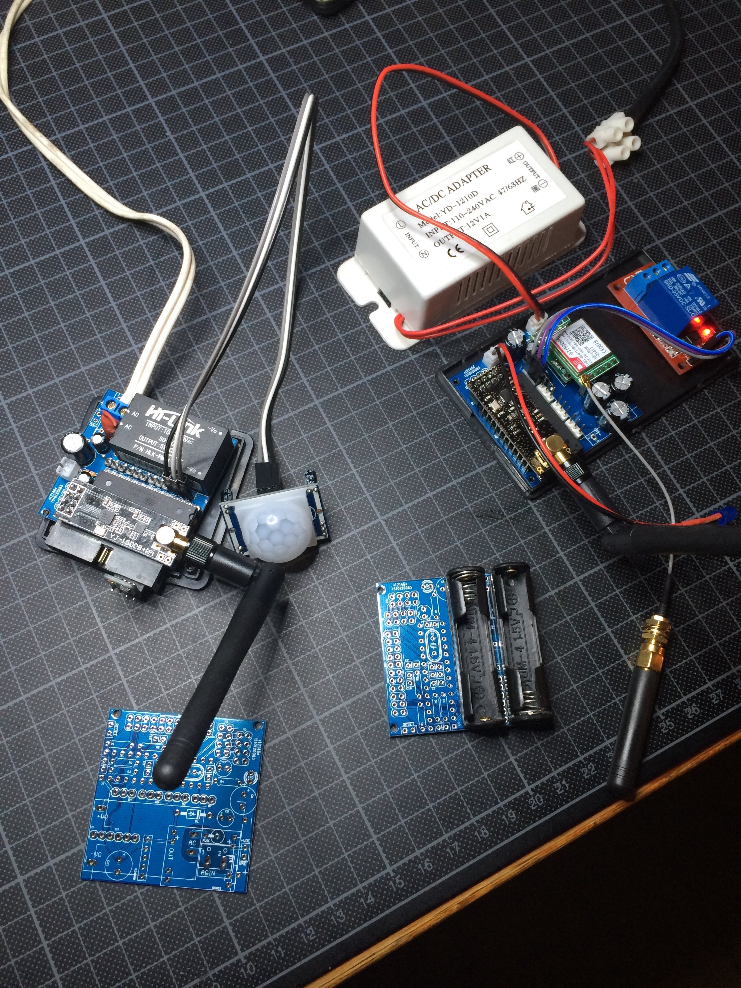
@alexsh1 It is based on my AC capable board, is a normal atmega328p board, but with a SIM800L mounted on it. This module allows me to send and receive SMS's, and I use one of the digital output pins to control a waterpump. I have a second AC based board ready which will be my MySensors SMS gateway. This means it will be able to receive V_TEXT and send that to the default GSM number as a SMS. It should be possible to receive SMS and send that as V_TEXT to other nodes, but so far I have not started the design of the second sketch yet.
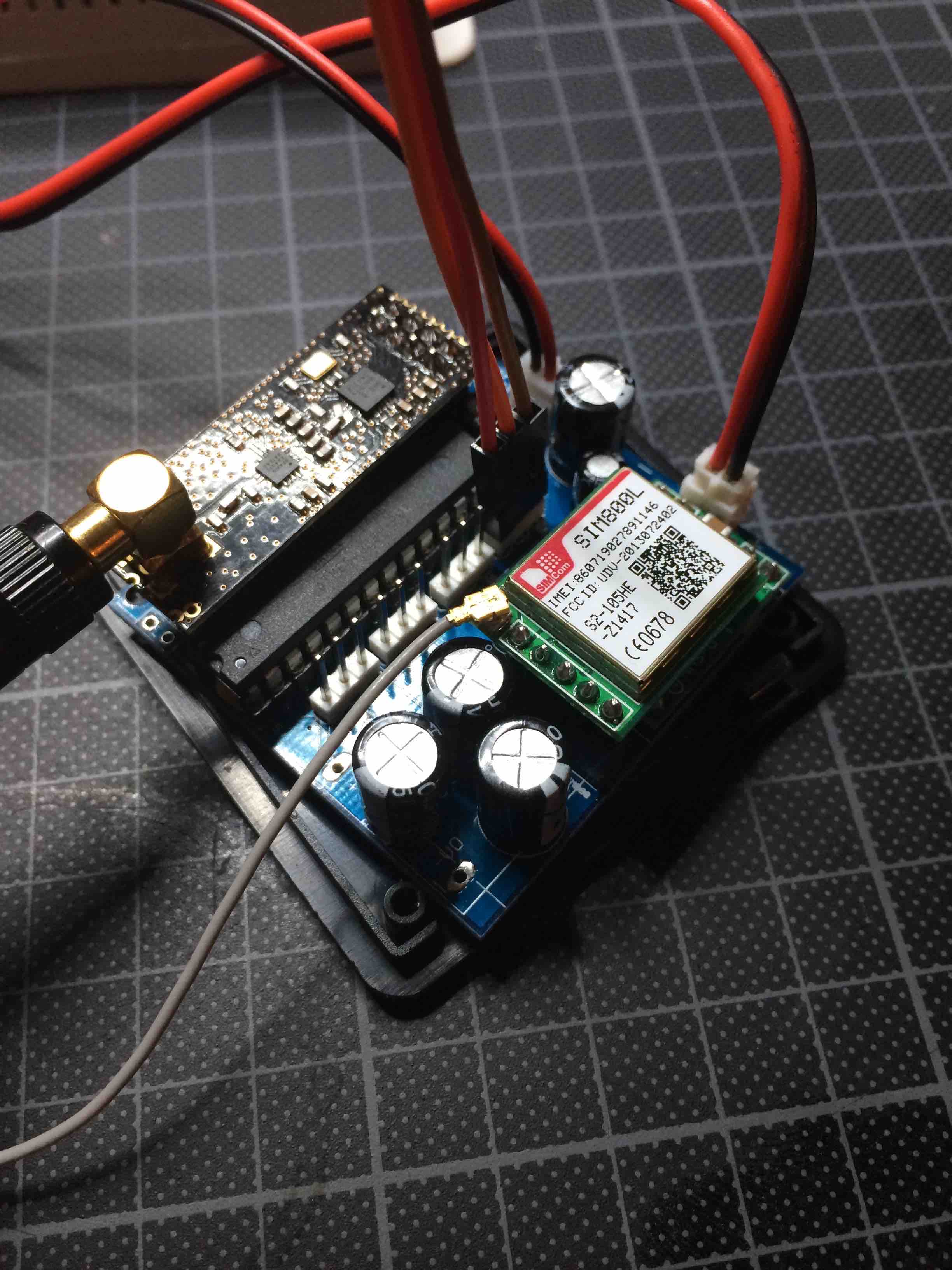
You see it here also (top right) with the relay module and the white AC-DC converter connected.
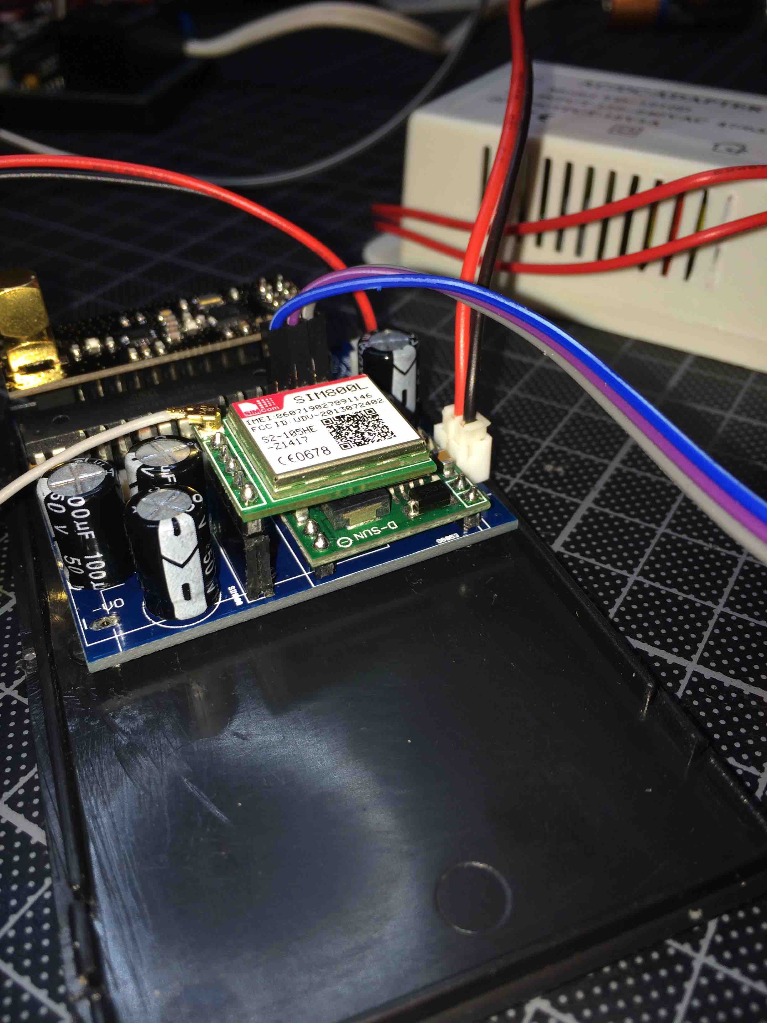
Side view:
-
@alexsh1 It is based on my AC capable board, is a normal atmega328p board, but with a SIM800L mounted on it. This module allows me to send and receive SMS's, and I use one of the digital output pins to control a waterpump. I have a second AC based board ready which will be my MySensors SMS gateway. This means it will be able to receive V_TEXT and send that to the default GSM number as a SMS. It should be possible to receive SMS and send that as V_TEXT to other nodes, but so far I have not started the design of the second sketch yet.
You see it here also (top right) with the relay module and the white AC-DC converter connected.
Side view:
@GertSanders said:
@alexsh1 It is based on my AC capable board, is a normal atmega328p board, but with a SIM800L mounted on it. This module allows me to send and receive SMS's, and I use one of the digital output pins to control a waterpump. I have a second AC based board ready which will be my MySensors SMS gateway. This means it will be able to receive V_TEXT and send that to the default GSM number as a SMS. It should be possible to receive SMS and send that as V_TEXT to other nodes, but so far I have not started the design of the second sketch yet.
I only have 1-2 high current (3kWh at 240V resistive load) devices at home and I am already controlling them as well my internet router (remote reboot if no internet) via SMS. At this stage I need a larger property to expand my home automation lol :satisfied: :satisfied: :satisfied:
-
@GertSanders
Do you have a source or shop for the AAA battery holder with solder pins? I did only find some for AA batteries.@gloob said:
@GertSanders
Do you have a source or shop for the AAA battery holder with solder pins? I did only find some for AA batteries.Would you mind me asking why you'd need AAA batteries? Much less capacity and the holder is not much smaller. I have been using Eneloop AA rechargable lithium batteries (http://www.ebay.co.uk/itm/4pcs-1-5V-AA-2200mWh-Lithium-li-ion-Rechargeble-Battery-4-PORTS-AA-charger-/272027421169?hash=item3f561909f1:g:r9AAAOSwMTZWSFHz) and they are holding up really well. The advantage is that they hold 1.5V almost until they are discharged unlike NiMh
-
@gloob I got my AAA holders from Aliexpress.
-
-
Indeed, those :+1:
-
@gloob Not yet, some of mine have been running for 2months with a voltage drop of less then 1%
-
@gloob There are two connections on the board to allow soldering the battery holder. Both the AA and AAA versions I use have the same pin spacing (seems standard), so you can use an AA battery holder as @alexsh1 does, or an AAA as I have.
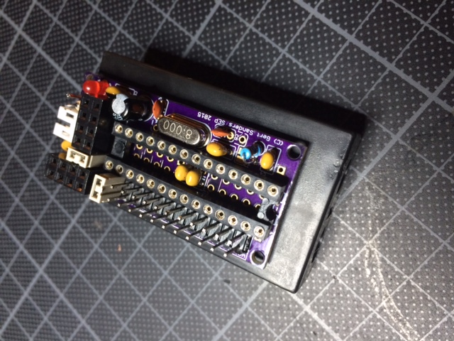
http://forum.mysensors.org/uploads/files/1446751714416-image.jpeg
The red arrows show where the batteryholder pins should go. If you have individual AAA battery holders, then the pins surrounded by yellow circle are also used to connect the batteries in series. If the battery holder holds 2 batteries, then only the pins pointed to by red arrows are used.
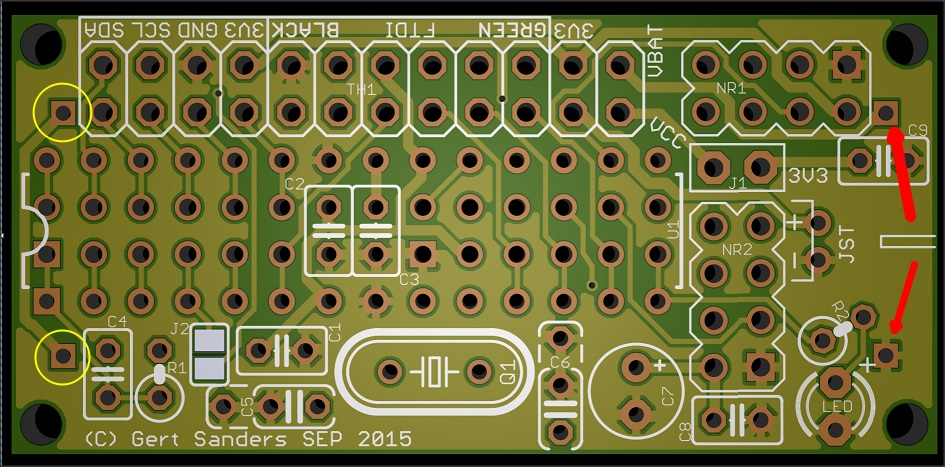
The PLUS sign next the the pin on the lower right of the above image is for the LED, the polarity of the pins from the battery is marked on the silkscreen of the bottom side. Looking at it from the top side, the pin above right is for Positive, the pin on below right is for Negative (or GND).
Jumper J2 is to connect the IRQ pin from the NRF24 to pin 2 (INT0) of the atmega328. You could also use that to connect a switch between the top jumper pad (connected to pin 2) and the extra ground pin of C5, to use with a doorswitch. I have used this with the internal pull up, but that would not be very good for the battery-use. It is better to use a 1MOhm pull up resistor wich can also be connected using the extra hole connected to pin 2 and Vcc
-
@alexsh1 I completely switched off the BoD in my fuse settings, this saves the battery even more. I found that the processor kept working down to around 1,64V. Even my NRF24 worked to that low level, because the last message I received in my Domoticz from that node gave a battery voltage of 1.64V
Anyway, since I monitor all battery levels via a script in Domoticz, there is no need for BoD.@GertSanders said:
@alexsh1 I completely switched off the BoD in my fuse settings, this saves the battery even more. I found that the processor kept working down to around 1,64V. Even my NRF24 worked to that low level, because the last message I received in my Domoticz from that node gave a battery voltage of 1.64V
Anyway, since I monitor all battery levels via a script in Domoticz, there is no need for BoD.How is 1.64v possible,It was my understanding that 8Mhz requires a minimum of 2.4v?
Hello! It looks like you're interested in this conversation, but you don't have an account yet.
Getting fed up of having to scroll through the same posts each visit? When you register for an account, you'll always come back to exactly where you were before, and choose to be notified of new replies (either via email, or push notification). You'll also be able to save bookmarks and upvote posts to show your appreciation to other community members.
With your input, this post could be even better 💗
Register Login