Skip to content
  • MySensors
  • OpenHardware.io
  • Categories
  • Recent
  • Tags
  • Popular
Skins
  • Light
  • Brite
  • Cerulean
  • Cosmo
  • Flatly
  • Journal
  • Litera
  • Lumen
  • Lux
  • Materia
  • Minty
  • Morph
  • Pulse
  • Sandstone
  • Simplex
  • Sketchy
  • Spacelab
  • United
  • Yeti
  • Zephyr
  • Dark
  • Cyborg
  • Darkly
  • Quartz
  • Slate
  • Solar
  • Superhero
  • Vapor

  • Default (No Skin)
  • No Skin
Collapse
Brand Logo
  1. Home
  2. Hardware
  3. What radio to use? NRF24L01+, RFM69, RFM73 ?

What radio to use? NRF24L01+, RFM69, RFM73 ?

Scheduled Pinned Locked Moved Hardware
52 Posts 11 Posters 49.2k Views 9 Watching
  • Oldest to Newest
  • Newest to Oldest
  • Most Votes
Reply
  • Reply as topic
Log in to reply
This topic has been deleted. Only users with topic management privileges can see it.
  • Cliff KarlssonC Offline
    Cliff KarlssonC Offline
    Cliff Karlsson
    wrote on last edited by
    #21

    Thanks, sorry for repeating the question but do I need to alter the code on gateway or sensors?

    1 Reply Last reply
    0
    • fetsF Offline
      fetsF Offline
      fets
      wrote on last edited by
      #22

      You only need to create a MyTransportRFM69 instead of MyTransportNRF24. This is the constructor : MyTransportRFM69 (RFM69_FREQUENCY, RFM69_NETWORKID, RF69_SPI_CS, RF69_IRQ_PIN, isRFM69HW, RF69_IRQ_NUM);
      if you use a RFM99H, you have to set the 5th parameter (isRFMHW) to true.

      1 Reply Last reply
      0
      • Cliff KarlssonC Offline
        Cliff KarlssonC Offline
        Cliff Karlsson
        wrote on last edited by
        #23

        Sorry for being semi-retarded, but is this done in the gateway sketch? Sensor
        -sketch or both? Is there any documentation on this part as I am a complete beginner.

        1 Reply Last reply
        0
        • fetsF Offline
          fetsF Offline
          fets
          wrote on last edited by
          #24

          both, here is the documentation

          1 Reply Last reply
          0
          • FrancoisF Offline
            FrancoisF Offline
            Francois
            wrote on last edited by Francois
            #25

            @Cliff-Karlsson You have to change the following setting in Myconfig.h for you radio

            
            /**********************************
            *  RFM69 Driver Defaults
            ***********************************/
            // Default network id. Use the same for all nodes that will talk to each other
            #define RFM69_NETWORKID     100
            
            // Default frequency to use. This must match the hardware version of the RFM69 radio (uncomment one):
             #define RFM69_FREQUENCY   RF69_433MHZ
            //#define RFM69_FREQUENCY   RF69_868MHZ
            //#define FREQUENCY     RF69_915MHZ
            
            // Enable this for encryption of packets
            //#define RFM69_ENABLE_ENCRYPTION
            #define RFM69_ENCRYPTKEY  "sampleEncryptKey"


            Then in MySensor.h you change the following:

            ifndef MySensor_h
            #define MySensor_h
            #include "Version.h"   // Auto generated by bot
            #include "MyConfig.h"
            #include "MyHw.h"
            #include "MyTransport.h"
            //#include "MyTransportNRF24.h"
            #include "MyTransportRFM69.h" 
            #include "MyParser.h"
            #ifdef MY_SIGNING_FEATURE
            #include "MySigning.h"
            #include "MySigningNone.h"
            #endif
            #include "MyMessage.h"
            #ifdef MY_OTA_FIRMWARE_FEATURE
            #include "utility/SPIFlash.h"
            #endif
            #include <stddef.h>
            #include <stdarg.h>```
            
            
            // look for this lines and changes this
            
            class MySensor
            {
              public:
            	/**
            	* Constructor
            	*
            	* Creates a new instance of Sensor class.
            	*
            	*/
            	//MySensor(MyTransport &radio =*new MyTransportNRF24(), MyHw &hw=*new MyHwDriver()
            	MySensor(MyTransport &radio =*new MyTransportRFM69(), MyHw &hw=*new MyHwDriver()
            1 Reply Last reply
            0
            • Cliff KarlssonC Offline
              Cliff KarlssonC Offline
              Cliff Karlsson
              wrote on last edited by
              #26

              @fets said:

              MyTransportRFM69 (RFM69_FREQUENCY, RFM69_NETWORKID, RF69_SPI_CS, RF69_IRQ_PIN, isRFM69HW, RF69_IRQ_NUM);

              Hmm. I can't get it to work. This is what I have done:
              In Myconfig.H:

              Everything was already set up like the example only 868Mhz was uncommented and that is the same as I got.

              Mysensors.h:

              Commented #include "MyTransportNRF24.h" as in the example.
              Added "#include "MyTransportRFM69.h" as it was not present.

              Under class Mysensor,
              Commented "MySensor(MyTransport &radio =*new MyTransportNRF24(), MyHw &hw=*new MyHwDriver()"
              Added "MySensor(MyTransport &radio =*new MyTransportRFM69(), MyHw &hw=*new MyHwDriver()"

              In the Serial Gateway sketch:
              Commented the line "#include <MyTransportNRF24.h>"
              Commented the line "MyTransportNRF24 transport(RF24_CE_PIN, RF24_CS_PIN, RF24_PA_LEVEL_GW);"
              Added the line "MyTransportRFM69 (RFM69_FREQUENCY, RFM69_NETWORKID, RF69_SPI_CS, RF69_IRQ_PIN, isRFM69HW=true, RF69_IRQ_NUM);

              When trying to upload to my nano I get an error:

              'transport' was not declared in this scope.
              And this line is highlighted: MySensor gw(transport, hw /, signer/);

              fetsF 1 Reply Last reply
              0
              • Cliff KarlssonC Cliff Karlsson

                @fets said:

                MyTransportRFM69 (RFM69_FREQUENCY, RFM69_NETWORKID, RF69_SPI_CS, RF69_IRQ_PIN, isRFM69HW, RF69_IRQ_NUM);

                Hmm. I can't get it to work. This is what I have done:
                In Myconfig.H:

                Everything was already set up like the example only 868Mhz was uncommented and that is the same as I got.

                Mysensors.h:

                Commented #include "MyTransportNRF24.h" as in the example.
                Added "#include "MyTransportRFM69.h" as it was not present.

                Under class Mysensor,
                Commented "MySensor(MyTransport &radio =*new MyTransportNRF24(), MyHw &hw=*new MyHwDriver()"
                Added "MySensor(MyTransport &radio =*new MyTransportRFM69(), MyHw &hw=*new MyHwDriver()"

                In the Serial Gateway sketch:
                Commented the line "#include <MyTransportNRF24.h>"
                Commented the line "MyTransportNRF24 transport(RF24_CE_PIN, RF24_CS_PIN, RF24_PA_LEVEL_GW);"
                Added the line "MyTransportRFM69 (RFM69_FREQUENCY, RFM69_NETWORKID, RF69_SPI_CS, RF69_IRQ_PIN, isRFM69HW=true, RF69_IRQ_NUM);

                When trying to upload to my nano I get an error:

                'transport' was not declared in this scope.
                And this line is highlighted: MySensor gw(transport, hw /, signer/);

                fetsF Offline
                fetsF Offline
                fets
                wrote on last edited by
                #27

                @Cliff-Karlsson, sorry for my late answer.
                you made a mistake on the line added in the serialgateway, it should be :
                MyTransportRFM69 transport (RFM69_FREQUENCY, RFM69_NETWORKID, RF69_SPI_CS, RF69_IRQ_PIN, true, RF69_IRQ_NUM) ;

                1 Reply Last reply
                0
                • GertSandersG Offline
                  GertSandersG Offline
                  GertSanders
                  Hardware Contributor
                  wrote on last edited by
                  #28

                  Has anyone used the Raspberry Pi Gateway implementation with an Rf69? Does it work? On which pin does one connect the interrupt pin ?

                  1 Reply Last reply
                  0
                  • Cliff KarlssonC Offline
                    Cliff KarlssonC Offline
                    Cliff Karlsson
                    wrote on last edited by Cliff Karlsson
                    #29

                    @fets said:

                    Personnaly I use 3 * 2 resistors (10k and 4.7k) for NS, MOSI and SCK rfm69hw inputs.

                    Ok, I am continuing with my neverending story :) I have gotten the sketches to complie and I have used a 8.6cm wire as antenna for both of them. But I still does not se any sensors in domoticz. I might have destroyed my radios as I might have accidently used 5 volts on them for a short while. I am trying to use some new radios this time.

                    First question: I have a RFM69HW on my gateway and a RFM69W on my sensor (both 868Mhz) They are compatible as I understand only that the H is more powerful?

                    Second question: If I am using a Nano I can just cut a cable in two and solder a 10k and a 4.7k in series in between them before connecting the NS, MOSI and SCK ? When checking online voltage divider calculators online and specify 5V in and 10k + 4,7k resistors it says that voltage out is 1.599v

                    NeverDieN fetsF 2 Replies Last reply
                    0
                    • Cliff KarlssonC Cliff Karlsson

                      @fets said:

                      Personnaly I use 3 * 2 resistors (10k and 4.7k) for NS, MOSI and SCK rfm69hw inputs.

                      Ok, I am continuing with my neverending story :) I have gotten the sketches to complie and I have used a 8.6cm wire as antenna for both of them. But I still does not se any sensors in domoticz. I might have destroyed my radios as I might have accidently used 5 volts on them for a short while. I am trying to use some new radios this time.

                      First question: I have a RFM69HW on my gateway and a RFM69W on my sensor (both 868Mhz) They are compatible as I understand only that the H is more powerful?

                      Second question: If I am using a Nano I can just cut a cable in two and solder a 10k and a 4.7k in series in between them before connecting the NS, MOSI and SCK ? When checking online voltage divider calculators online and specify 5V in and 10k + 4,7k resistors it says that voltage out is 1.599v

                      NeverDieN Offline
                      NeverDieN Offline
                      NeverDie
                      Hero Member
                      wrote on last edited by
                      #30

                      First question: I have a RFM69HW on my gateway and a RFM69W on my sensor (both 868Mhz) They are compatible as I understand only that the H is more powerful?

                      Assuming they are of the same frequency, then basically yes, though there is one small difference in the code to account for the RFM69HW having a PA, which MUST be turned on for it to transmit.

                      1 Reply Last reply
                      0
                      • Cliff KarlssonC Cliff Karlsson

                        @fets said:

                        Personnaly I use 3 * 2 resistors (10k and 4.7k) for NS, MOSI and SCK rfm69hw inputs.

                        Ok, I am continuing with my neverending story :) I have gotten the sketches to complie and I have used a 8.6cm wire as antenna for both of them. But I still does not se any sensors in domoticz. I might have destroyed my radios as I might have accidently used 5 volts on them for a short while. I am trying to use some new radios this time.

                        First question: I have a RFM69HW on my gateway and a RFM69W on my sensor (both 868Mhz) They are compatible as I understand only that the H is more powerful?

                        Second question: If I am using a Nano I can just cut a cable in two and solder a 10k and a 4.7k in series in between them before connecting the NS, MOSI and SCK ? When checking online voltage divider calculators online and specify 5V in and 10k + 4,7k resistors it says that voltage out is 1.599v

                        fetsF Offline
                        fetsF Offline
                        fets
                        wrote on last edited by
                        #31

                        @Cliff-Karlsson,
                        question 2 : I think you misplaced the connection to RFM69 :
                        Here is how to connect arduino and RFM69.
                        Is it what you did ? (I bet you switched 4.7k ans 10k )

                        divisor.png

                        1 Reply Last reply
                        0
                        • Cliff KarlssonC Offline
                          Cliff KarlssonC Offline
                          Cliff Karlsson
                          wrote on last edited by
                          #32

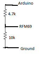
                          I am still having some problems with getting any data from the RFM69.

                          Do I need to define some pins to like in the NRF24L01 section in the Myconfig.h ?
                          I have not defined any pins anywhere for the RFM69 or do I not need to do that?

                          /**********************************
                          *  NRF24L01 Driver Defaults
                          ***********************************/
                          #define RF24_CE_PIN		   9
                          #define RF24_CS_PIN		   10
                          #define RF24_PA_LEVEL 	   RF24_PA_MAX
                          #define RF24_PA_LEVEL_GW   RF24_PA_LOW
                          // RF channel for the sensor net, 0-127
                          #define RF24_CHANNEL	   76
                          //RF24_250KBPS for 250kbs, RF24_1MBPS for 1Mbps, or RF24_2MBPS for 2Mbps
                          #define RF24_DATARATE 	   RF24_250KBPS
                          // This is also act as base value for sensor nodeId addresses. Change this (or channel) if you have more than one sensor network.
                          #define RF24_BASE_RADIO_ID ((uint64_t)0xA8A8E1FC00LL)
                          
                          // Enable SOFTSPI for NRF24L01 when using the W5100 Ethernet module
                          //#define SOFTSPI
                          #ifdef SOFTSPI
                          	// Define the soft SPI pins used for NRF radio
                          	const uint8_t SOFT_SPI_MISO_PIN = 16;
                              const uint8_t SOFT_SPI_MOSI_PIN = 15;
                              const uint8_t SOFT_SPI_SCK_PIN = 14;
                          #endif
                          
                          
                          /**********************************
                          *  RFM69 Driver Defaults
                          ***********************************/
                          // Default network id. Use the same for all nodes that will talk to each other
                          #define RFM69_NETWORKID     100
                          
                          // Default frequency to use. This must match the hardware version of the RFM69 radio (uncomment one):
                          // #define RFM69_FREQUENCY   RF69_433MHZ
                          #define RFM69_FREQUENCY   RF69_868MHZ
                          //#define FREQUENCY     RF69_915MHZ
                          
                          // Enable this for encryption of packets
                          //#define RFM69_ENABLE_ENCRYPTION
                          #define RFM69_ENCRYPTKEY    "sampleEncryptKey" //exactly the same 16 characters/bytes on all nodes!```
                          1 Reply Last reply
                          0
                          • Cliff KarlssonC Offline
                            Cliff KarlssonC Offline
                            Cliff Karlsson
                            wrote on last edited by
                            #33

                            I even sent a mail to hek asking for help and he said that the only thing I needed to do was to add the line:

                            MyTransportRFM69 transport;

                            in the serial gateway sketch and "construct your mysensor class with" : MySensor gw(transport);

                            I added those two lines in the serial gateway sketch and it complied and uploaded ok but as usual it does not work for me. Can someone give me the exact sketch for a serial gateway using the RFM69W radio and the dallas temperature sketch that is provided on the mysensors-build page modified for use with RFM69W? I would be forever grateful :)

                            1 Reply Last reply
                            0
                            • Cliff KarlssonC Offline
                              Cliff KarlssonC Offline
                              Cliff Karlsson
                              wrote on last edited by
                              #34

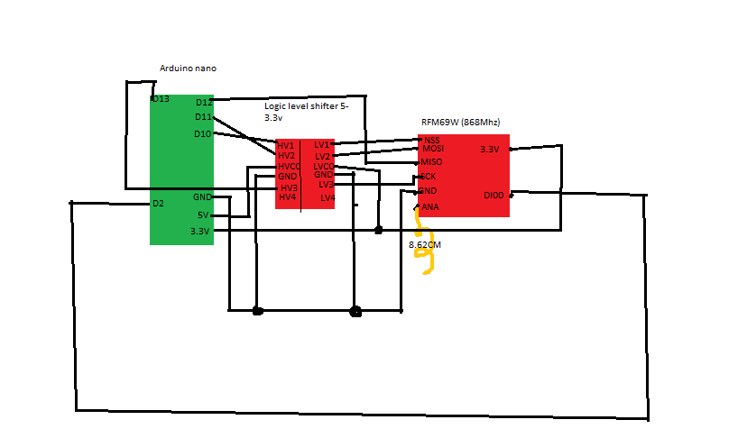
                              Still trying, can anyone tell me if this is correct: Nano-Levelshifter-RFM69W

                              Untitled.png

                              1 Reply Last reply
                              0
                              • hekH Offline
                                hekH Offline
                                hek
                                Admin
                                wrote on last edited by
                                #35

                                Shouldn't D2-> DI00 have level shifting as well?

                                1 Reply Last reply
                                0
                                • TD22057T Offline
                                  TD22057T Offline
                                  TD22057
                                  Hardware Contributor
                                  wrote on last edited by
                                  #36

                                  @hek said:

                                  Shouldn't D2-> DI00 have level shifting as well?

                                  That's IRQ so it should be an output from the radio to the arduino just like MISO right? I was under the impression that radio->arduino links didn't need to be shifted since they're digital connections and the arduino will read 3.3V as HIGH. I could be mistaken of course...

                                  @Cliff-Karlsson I'm going to start my RFM69 radio testing this weekend (finally) using ProMini 5V <-> level shifter <-> RFM69W so hopefully I can report back with something that works.

                                  Anytime you have trouble, you should start w/ the simplest case and build up to a real case. So:

                                  1. use a serial gateway. start it up w/ debug output and make sure that the radio initializes properly.
                                  2. use the MockMySensors sketch or take a simple sketch and modify it to send an increasing counter value (1,2,3...) every second. start that w/ debug print as well (run 2 arduino ide's so you can use 2 serial monitor windows). That will tell you if the radios are receiving each other properly. You can use this to test range as well my moving one of the radios to another location.
                                  3. create a simple arduino sketch that reads the sensor. it shouldn't have any mysensors code in it. just report the sensor values to the serial connection. make sure that works. This validates the sensor reading and wiring code.
                                  4. combine 2+3 so you're sending real data to the gateway == success!
                                  1 Reply Last reply
                                  0
                                  • Cliff KarlssonC Offline
                                    Cliff KarlssonC Offline
                                    Cliff Karlsson
                                    wrote on last edited by Cliff Karlsson
                                    #37

                                    Well I am not very experienced so even the trivial task of creating a simple sketch would prove a challenge for me :).

                                    But this is the SerialGateway sketch I am using:

                                    #define NO_PORTB_PINCHANGES  
                                    
                                    #include <MySigningNone.h>
                                    #include <MyTransportRFM69.h>
                                    //#include <MyTransportNRF24.h>
                                    #include <MyHwATMega328.h>
                                    #include <MySigningAtsha204Soft.h>
                                    #include <MySigningAtsha204.h>
                                    
                                    #include <SPI.h>  
                                    #include <MyParserSerial.h>  
                                    #include <MySensor.h>  
                                    #include <stdarg.h>
                                    #include <PinChangeInt.h>
                                    #include "GatewayUtil.h"
                                    
                                    #define INCLUSION_MODE_TIME 1 // Number of minutes inclusion mode is enabled
                                    #define INCLUSION_MODE_PIN  3 // Digital pin used for inclusion mode button
                                    #define RADIO_ERROR_LED_PIN 4  // Error led pin
                                    #define RADIO_RX_LED_PIN    6  // Receive led pin
                                    #define RADIO_TX_LED_PIN    5  // the PCB, on board LED
                                    
                                    // NRFRF24L01 radio driver (set low transmit power by default) 
                                    //MyTransportNRF24 transport(RF24_CE_PIN, RF24_CS_PIN, RF24_PA_LEVEL_GW);
                                    //MyTransportRFM69 transport;
                                    MyTransportRFM69 transport(RFM69_FREQUENCY, RFM69_NETWORKID, RF69_SPI_CS, RF69_IRQ_PIN, false, RF69_IRQ_NUM);
                                    
                                    // Message signing driver (signer needed if MY_SIGNING_FEATURE is turned on in MyConfig.h)
                                    //MySigningNone signer;
                                    //MySigningAtsha204Soft signer;
                                    //MySigningAtsha204 signer;
                                    
                                    // Hardware profile 
                                    MyHwATMega328 hw;
                                    
                                    // Construct MySensors library (signer needed if MY_SIGNING_FEATURE is turned on in MyConfig.h)
                                    // To use LEDs blinking, uncomment WITH_LEDS_BLINKING in MyConfig.h
                                    #ifdef WITH_LEDS_BLINKING
                                    MySensor gw(transport, hw /*, signer*/, RADIO_RX_LED_PIN, RADIO_TX_LED_PIN, RADIO_ERROR_LED_PIN);
                                    #else
                                    MySensor gw(transport, hw /*, signer*/);
                                    #endif
                                    
                                    char inputString[MAX_RECEIVE_LENGTH] = "";    // A string to hold incoming commands from serial/ethernet interface
                                    int inputPos = 0;
                                    boolean commandComplete = false;  // whether the string is complete
                                    
                                    void parseAndSend(char *commandBuffer);
                                    
                                    void output(const char *fmt, ... ) {
                                       va_list args;
                                       va_start (args, fmt );
                                       vsnprintf_P(serialBuffer, MAX_SEND_LENGTH, fmt, args);
                                       va_end (args);
                                       Serial.print(serialBuffer);
                                    }
                                    
                                      
                                    void setup()  
                                    { 
                                      gw.begin(incomingMessage, 0, true, 0);
                                    
                                      setupGateway(INCLUSION_MODE_PIN, INCLUSION_MODE_TIME, output);
                                    
                                      // Add interrupt for inclusion button to pin
                                      PCintPort::attachInterrupt(pinInclusion, startInclusionInterrupt, RISING);
                                    
                                    
                                      // Send startup log message on serial
                                      serial(PSTR("0;0;%d;0;%d;Gateway startup complete.\n"),  C_INTERNAL, I_GATEWAY_READY);
                                    }
                                    
                                    void loop()  
                                    { 
                                      gw.process();
                                    
                                      checkButtonTriggeredInclusion();
                                      checkInclusionFinished();
                                      
                                      if (commandComplete) {
                                        // A command wass issued from serial interface
                                        // We will now try to send it to the actuator
                                        parseAndSend(gw, inputString);
                                        commandComplete = false;  
                                        inputPos = 0;
                                      }
                                    }
                                    
                                    
                                    /*
                                      SerialEvent occurs whenever a new data comes in the
                                     hardware serial RX.  This routine is run between each
                                     time loop() runs, so using delay inside loop can delay
                                     response.  Multiple bytes of data may be available.
                                     */
                                    void serialEvent() {
                                      while (Serial.available()) {
                                        // get the new byte:
                                        char inChar = (char)Serial.read(); 
                                        // if the incoming character is a newline, set a flag
                                        // so the main loop can do something about it:
                                        if (inputPos<MAX_RECEIVE_LENGTH-1 && !commandComplete) { 
                                          if (inChar == '\n') {
                                            inputString[inputPos] = 0;
                                            commandComplete = true;
                                          } else {
                                            // add it to the inputString:
                                            inputString[inputPos] = inChar;
                                            inputPos++;
                                          }
                                        } else {
                                           // Incoming message too long. Throw away 
                                            inputPos = 0;
                                        }
                                      }
                                    }


                                    Does it look alright? I am fairly sure that I also tried using MyTransportRFM69 transport;
                                    instead of MyTransportRFM69 transport(RFM69_FREQUENCY, RFM69_NETWORKID, RF69_SPI_CS, RF69_IRQ_PIN, false, RF69_IRQ_NUM);
                                    In the serial monitor only this shows:

                                    0;0;3;0;9;gateway started, id=0, parent=0, distance=0
                                    0;0;3;0;14;Gateway startup complete.

                                    fetsF 1 Reply Last reply
                                    0
                                    • hekH Offline
                                      hekH Offline
                                      hek
                                      Admin
                                      wrote on last edited by
                                      #38

                                      Yes, it looks right.

                                      1 Reply Last reply
                                      0
                                      • Cliff KarlssonC Cliff Karlsson

                                        Well I am not very experienced so even the trivial task of creating a simple sketch would prove a challenge for me :).

                                        But this is the SerialGateway sketch I am using:

                                        #define NO_PORTB_PINCHANGES  
                                        
                                        #include <MySigningNone.h>
                                        #include <MyTransportRFM69.h>
                                        //#include <MyTransportNRF24.h>
                                        #include <MyHwATMega328.h>
                                        #include <MySigningAtsha204Soft.h>
                                        #include <MySigningAtsha204.h>
                                        
                                        #include <SPI.h>  
                                        #include <MyParserSerial.h>  
                                        #include <MySensor.h>  
                                        #include <stdarg.h>
                                        #include <PinChangeInt.h>
                                        #include "GatewayUtil.h"
                                        
                                        #define INCLUSION_MODE_TIME 1 // Number of minutes inclusion mode is enabled
                                        #define INCLUSION_MODE_PIN  3 // Digital pin used for inclusion mode button
                                        #define RADIO_ERROR_LED_PIN 4  // Error led pin
                                        #define RADIO_RX_LED_PIN    6  // Receive led pin
                                        #define RADIO_TX_LED_PIN    5  // the PCB, on board LED
                                        
                                        // NRFRF24L01 radio driver (set low transmit power by default) 
                                        //MyTransportNRF24 transport(RF24_CE_PIN, RF24_CS_PIN, RF24_PA_LEVEL_GW);
                                        //MyTransportRFM69 transport;
                                        MyTransportRFM69 transport(RFM69_FREQUENCY, RFM69_NETWORKID, RF69_SPI_CS, RF69_IRQ_PIN, false, RF69_IRQ_NUM);
                                        
                                        // Message signing driver (signer needed if MY_SIGNING_FEATURE is turned on in MyConfig.h)
                                        //MySigningNone signer;
                                        //MySigningAtsha204Soft signer;
                                        //MySigningAtsha204 signer;
                                        
                                        // Hardware profile 
                                        MyHwATMega328 hw;
                                        
                                        // Construct MySensors library (signer needed if MY_SIGNING_FEATURE is turned on in MyConfig.h)
                                        // To use LEDs blinking, uncomment WITH_LEDS_BLINKING in MyConfig.h
                                        #ifdef WITH_LEDS_BLINKING
                                        MySensor gw(transport, hw /*, signer*/, RADIO_RX_LED_PIN, RADIO_TX_LED_PIN, RADIO_ERROR_LED_PIN);
                                        #else
                                        MySensor gw(transport, hw /*, signer*/);
                                        #endif
                                        
                                        char inputString[MAX_RECEIVE_LENGTH] = "";    // A string to hold incoming commands from serial/ethernet interface
                                        int inputPos = 0;
                                        boolean commandComplete = false;  // whether the string is complete
                                        
                                        void parseAndSend(char *commandBuffer);
                                        
                                        void output(const char *fmt, ... ) {
                                           va_list args;
                                           va_start (args, fmt );
                                           vsnprintf_P(serialBuffer, MAX_SEND_LENGTH, fmt, args);
                                           va_end (args);
                                           Serial.print(serialBuffer);
                                        }
                                        
                                          
                                        void setup()  
                                        { 
                                          gw.begin(incomingMessage, 0, true, 0);
                                        
                                          setupGateway(INCLUSION_MODE_PIN, INCLUSION_MODE_TIME, output);
                                        
                                          // Add interrupt for inclusion button to pin
                                          PCintPort::attachInterrupt(pinInclusion, startInclusionInterrupt, RISING);
                                        
                                        
                                          // Send startup log message on serial
                                          serial(PSTR("0;0;%d;0;%d;Gateway startup complete.\n"),  C_INTERNAL, I_GATEWAY_READY);
                                        }
                                        
                                        void loop()  
                                        { 
                                          gw.process();
                                        
                                          checkButtonTriggeredInclusion();
                                          checkInclusionFinished();
                                          
                                          if (commandComplete) {
                                            // A command wass issued from serial interface
                                            // We will now try to send it to the actuator
                                            parseAndSend(gw, inputString);
                                            commandComplete = false;  
                                            inputPos = 0;
                                          }
                                        }
                                        
                                        
                                        /*
                                          SerialEvent occurs whenever a new data comes in the
                                         hardware serial RX.  This routine is run between each
                                         time loop() runs, so using delay inside loop can delay
                                         response.  Multiple bytes of data may be available.
                                         */
                                        void serialEvent() {
                                          while (Serial.available()) {
                                            // get the new byte:
                                            char inChar = (char)Serial.read(); 
                                            // if the incoming character is a newline, set a flag
                                            // so the main loop can do something about it:
                                            if (inputPos<MAX_RECEIVE_LENGTH-1 && !commandComplete) { 
                                              if (inChar == '\n') {
                                                inputString[inputPos] = 0;
                                                commandComplete = true;
                                              } else {
                                                // add it to the inputString:
                                                inputString[inputPos] = inChar;
                                                inputPos++;
                                              }
                                            } else {
                                               // Incoming message too long. Throw away 
                                                inputPos = 0;
                                            }
                                          }
                                        }


                                        Does it look alright? I am fairly sure that I also tried using MyTransportRFM69 transport;
                                        instead of MyTransportRFM69 transport(RFM69_FREQUENCY, RFM69_NETWORKID, RF69_SPI_CS, RF69_IRQ_PIN, false, RF69_IRQ_NUM);
                                        In the serial monitor only this shows:

                                        0;0;3;0;9;gateway started, id=0, parent=0, distance=0
                                        0;0;3;0;14;Gateway startup complete.

                                        fetsF Offline
                                        fetsF Offline
                                        fets
                                        wrote on last edited by
                                        #39

                                        @Cliff-Karlsson First time I used RFM69 I didn't adapt level and the RFM69 initialization couldn't complete : meaning I didn't have the message "Gateway startup complete"
                                        As soon as I used I used resistors to adapt levels, the initialization was fully completed.
                                        So I think that your connections are good.
                                        I think (from memory) that I created MyTransporRFM69 almost the same way as your (I use RFM69HW) :
                                        MyTransportRFM69 transport(RFM69_FREQUENCY, RFM69_NETWORKID, RF69_SPI_CS, RF69_IRQ_PIN, true, RF69_IRQ_NUM);

                                        What about your node sketch ? Do you do the same ?

                                        1 Reply Last reply
                                        0
                                        • NeverDieN Offline
                                          NeverDieN Offline
                                          NeverDie
                                          Hero Member
                                          wrote on last edited by
                                          #40

                                          I would wonder whether running some signals through the level shifter and some not might cause the signals to arrive out of phase? Anyway, something to consider if you can't get it to work.

                                          1 Reply Last reply
                                          0
                                          Reply
                                          • Reply as topic
                                          Log in to reply
                                          • Oldest to Newest
                                          • Newest to Oldest
                                          • Most Votes


                                          14

                                          Online

                                          11.7k

                                          Users

                                          11.2k

                                          Topics

                                          113.0k

                                          Posts


                                          Copyright 2019 TBD   |   Forum Guidelines   |   Privacy Policy   |   Terms of Service
                                          • Login

                                          • Don't have an account? Register

                                          • Login or register to search.
                                          • First post
                                            Last post
                                          0
                                          • MySensors
                                          • OpenHardware.io
                                          • Categories
                                          • Recent
                                          • Tags
                                          • Popular