My Ideal sensor node PCB
-
@Zeph said:
There's another candidate which meets this criterion for me, and I've edited it into the Origional Post - onboard external serial Flash.
Have a look at this little fella: http://www.digikey.com/product-search/en?mpart=W25X40CLSNIG&vendor=256
Isn't anybody willing to create a SOIC-8 home for this cute little chip (with SPI traces of course to keep it happy)?
512 KBytes of happiness for logging and OTA programming. Unique ID.
Or you can get twice that memory for 2 cents more.(The above is the chip used by the Moteino. The Anarduino uses a heftier 16 MByte chip: http://www.mouser.com/ProductDetail/Spansion/S25FL127SABMFI101/?qs=sGAEpiMZZMtI%252bQ06EiAoG5SEO4xJJ6RlEmMSz7h3HuQ%3D but that too is possible with the same SOIC-8 footprint, I think)
(The Moteino and Anarduino use different and incompatible radios compared to MySensors, but nevertheless contain possible inspirations for our corner of this exciting little world).
@Zeph said:
Have a look at this little fella: http://www.digikey.com/product-search/en?mpart=W25X40CLSNIG&vendor=256
Any proposals for DIP-8 flash to use for breadboard testing that are compatible to avoid surprises when switching to the SOT-8 ones later-on? Do all of these SPIflash chips use the same "protocol"?
-
Here's a dip version of the next larger brother from adafruit:for $1.95 https://www.adafruit.com/products/1564
Then digikey has the soic for $0.43
http://www.digikey.com/product-search/en?x=0&y=0&lang=en&site=us&keywords=W25Q80BV(Digikey has listings for the dip version but 0 stock)
I have not used these so I don't have any first hand recommendation. I cued in on this line because Felix uses the 4Mbit version on the Moteino, so I looked it up and thought it looked good.
(The Anarduino uses a 128 Mbit spi flash chip from a different line).
@Zeph
What I don't like about Flash is the need to erase before writing / the ability to erase only full sectors (4k if I get it right from the WB datasheet). Not a big deal for bootloading or logging where you can erase all upfront but limits the use-cases.
What I really like is that a lot of the SPI Flash chips and EEPROM chips have the same pinout - which means depending on the specific need you can use a flash or an EEPROM using the same PCB layout (example EEPROM that allows single byte writes without erase: 25LC256 - obviously less memory and higher price but serves different purpose - 256kbit for <1€)So I really like the idea of having this added to the PCB layout - especially because it can serve different needs depending on what chip is selected :)
-
@Zeph
What I don't like about Flash is the need to erase before writing / the ability to erase only full sectors (4k if I get it right from the WB datasheet). Not a big deal for bootloading or logging where you can erase all upfront but limits the use-cases.
What I really like is that a lot of the SPI Flash chips and EEPROM chips have the same pinout - which means depending on the specific need you can use a flash or an EEPROM using the same PCB layout (example EEPROM that allows single byte writes without erase: 25LC256 - obviously less memory and higher price but serves different purpose - 256kbit for <1€)So I really like the idea of having this added to the PCB layout - especially because it can serve different needs depending on what chip is selected :)
@ToSa
Yes that flexibiity is attractive.I don't have the datasheets right here, but...
Do I recall that there's often a way to test for the type and size of chip (that's actually installed) using SPI?
Do I recall that some include a unique ID?(I might be thinking of the 128 Mbit chip used by anarduino)
For bootloading one attraction is the possibility of letting application code fill and verify the external Flash using the full normal protocol (at the cost of some space in operational PROGMEM), then having a relatively simple boot-loader to transfer it to PROGMEM The sensor can continue to operate while packets are written to external flash, using high or low portions of the wireless bandwidth. When the application has finished loading and verifying the new firmware in external flash, it would write a "All OK, use this" signature to the external flash and reboot; the bootloader would notice that signature and copy from external flash to application PROGMEM.
In this case, the bootloader doesn't need to have a radio library or MySensors protocol stack (even trimmed down), and so there's no need to change the bootloader when the OTA protocol changes, eg MySensors 1.3 vs MySensors 1.4 vs RadioHead. Pretty much all the hardware config the bootloader would need is the select pin for the SPI flash. And if you were using a low bandwidth network (eg: 433 Mhz at 38400 bps) you could take as long as it needs to sent out firmware packets mixed with ongoing normal operation, before doing a sudden reboot/bootload.
That said, not every node is going to have external flash, so I'm happy to have the alternatives of your approach which doesn't require it.
-
Bandra,
Any chance we can get the files to order our own?
If I want to use this with a 5V regulated supply, how hard would it be to add a 5V-3.3V converter for the Radio?
Edward
-
Thanks for your interest, guys!
My PCB is getting really close, but I'm not entirely happy with it. I've made up 5 of them and scattered them around my place. For the most part, they're working well. However I have the following issues:
- The battery voltage varies. I don't think my cap is quite doing the job, so I may need to tweak the PCB to get it closer to the voltage divider. I'm running Domoticz and it does a good job of averaging the battery level out, so it's not completely bad, but I'd really like to fix it in the next version of the PCB.
- My moisture sensor (the one from the MySensors store) doesn't work very well. It chews the battery (cos the sensor from the store has 2 leds on it, plus it's always "on". I'll pop those off and see how it goes. However I think I can do the moisture sensor better. I'm thinking of including another voltage divider, and run the sensor off the digital pin for power. That way, I can power the sensor down in between samples.
I think that I can also include my own step up voltage converter. I'm not entirely happy with the chinese step up converter. So far my 2xAA batteries have lasted several weeks, and they're still going strong, but I suspect that I'll only get a few months out of them. I'm aiming for a year.
I'm designing our new house at the moment, which is taking up a lot of time, but I'll get onto rev 2 shortly. Once I'm happy with it, I'll put the design up here so that you guys can get your own made up.
-
Oh yeah, I'm also scouting around for a nice enclosure that will snugly fit the PCB and 2xAA battery holder side-by-side (around 60mmx 60mm) and with room for the PIR motion sensor sitting on top of those. Haven't found anything yet. I may have to buy a 3d printer to make my own... :)
-
Oh yeah, I'm also scouting around for a nice enclosure that will snugly fit the PCB and 2xAA battery holder side-by-side (around 60mmx 60mm) and with room for the PIR motion sensor sitting on top of those. Haven't found anything yet. I may have to buy a 3d printer to make my own... :)
-
Just for completeness, my PCBs came in and I've had a chance to solder them up. The PCBs are really nice. iTead have done a great job. @Zeph, turns out that I didn't need to cut my PCBs because the friendly folk at iTead cut them for me.
Here's a photo of a few things soldered on:
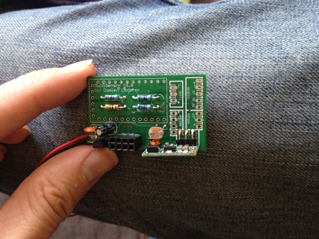
Underneath the APM I have a 1M and 470K resistors for the battery voltage check. There's also a 4.7K resistor for the Dallas DS18B20 temp sensor. Finally there's a 4.7K resistor for the LDR divider circuit.
You can also see the 4x2 header for the radio, the LDR itself, and the 3.3v step-up converter.
Here's the (almost) finished package:
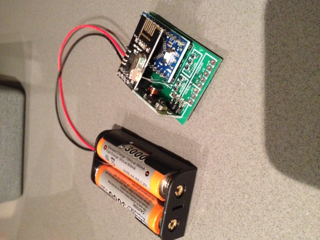
You can see all the exposed solder pads for my various sensor configurations (motion, humidity, baro pressure, door reed switch, distance and soil moisture).
The range on the nRF24 is fine. I put my gateway at one end of the apartment and it easily picked up my sensor at the other end of the apartment (about 10m away through two thick internal walls). So I'm not worried about the nRF24 being parallel to the GND plane.
I actually took off the 4.7uF cap. It's probably my PCB (don't think the auto-route did a great job of it) but it made the radio flaky. Works just fine without it.
Now to find a box to put it in...
-
@Bandra how are the boards working out?
Any issues with the Radio over the Arduino in terms of the RF capabilities?
I'm thinking I would like to change my board layout to have the radio like yours to save some real estate on the board if there are no negative consequences..Thanks,
Edward -
I did not know one could design and purchase a PCB for relatively cheap like this, awesome! Although, now I have yet another project on my hands, haha.
If anyone with a board plans to put their files public, please let me know. I would definitely be interested in purchasing, rather than teaching myself to design one. :) At least for now, while I have 5 million other projects going on.
-
Oh yeah, I'm also scouting around for a nice enclosure that will snugly fit the PCB and 2xAA battery holder side-by-side (around 60mmx 60mm) and with room for the PIR motion sensor sitting on top of those. Haven't found anything yet. I may have to buy a 3d printer to make my own... :)
-
Just for completeness, my PCBs came in and I've had a chance to solder them up. The PCBs are really nice. iTead have done a great job. @Zeph, turns out that I didn't need to cut my PCBs because the friendly folk at iTead cut them for me.
Here's a photo of a few things soldered on:
Underneath the APM I have a 1M and 470K resistors for the battery voltage check. There's also a 4.7K resistor for the Dallas DS18B20 temp sensor. Finally there's a 4.7K resistor for the LDR divider circuit.
You can also see the 4x2 header for the radio, the LDR itself, and the 3.3v step-up converter.
Here's the (almost) finished package:
You can see all the exposed solder pads for my various sensor configurations (motion, humidity, baro pressure, door reed switch, distance and soil moisture).
The range on the nRF24 is fine. I put my gateway at one end of the apartment and it easily picked up my sensor at the other end of the apartment (about 10m away through two thick internal walls). So I'm not worried about the nRF24 being parallel to the GND plane.
I actually took off the 4.7uF cap. It's probably my PCB (don't think the auto-route did a great job of it) but it made the radio flaky. Works just fine without it.
Now to find a box to put it in...
@Bandra said:
Just for completeness, my PCBs came in and I've had a chance to solder them up. The PCBs are really nice. iTead have done a great job. @Zeph, turns out that I didn't need to cut my PCBs because the friendly folk at iTead cut them for me.
Here's a photo of a few things soldered on:
Underneath the APM I have a 1M and 470K resistors for the battery voltage check. There's also a 4.7K resistor for the Dallas DS18B20 temp sensor. Finally there's a 4.7K resistor for the LDR divider circuit.
You can also see the 4x2 header for the radio, the LDR itself, and the 3.3v step-up converter.
Here's the (almost) finished package:
You can see all the exposed solder pads for my various sensor configurations (motion, humidity, baro pressure, door reed switch, distance and soil moisture).
The range on the nRF24 is fine. I put my gateway at one end of the apartment and it easily picked up my sensor at the other end of the apartment (about 10m away through two thick internal walls). So I'm not worried about the nRF24 being parallel to the GND plane.
I actually took off the 4.7uF cap. It's probably my PCB (don't think the auto-route did a great job of it) but it made the radio flaky. Works just fine without it.
Now to find a box to put it in...
Can you share your board to me,pls? Im newbie. Pls email to me quocanhcgd@gmail.com Thanks