My Slim 2AA Battery Node


  • Hardware Contributor

    NEWS:

    • A "final" version 2.0 redesigned i KiCad (very similar layout), panelized, ordered and tested OK.
    • A faulty via was introduced during panelization of v1.2, so the panelized v1.2 (blue board) needs a small fix to work.

    More info ASAP.

    Edit 4/11: There seems to be no issues with v1.4 (red board) as I thought first. Luckily since it's now been shared a few times.


  • Hero Member

    @m26872 I received the boards yesterday. Can you direct me to the fix needed.?


  • Hardware Contributor

    @AWI It should be easy the see the via with a missing hole. A connecting wire between Arduino D13 and nRF SCK is needed.
    fel.PNG


  • Hero Member

    @m26872 Tnhx, however my samples seems to be correct...

    upload-703db10b-132e-423d-bb85-1903bc043352


  • Hardware Contributor

    @AWI Mine too. I didn't see the red v1.4 until I got it today. Looks promising, but I've not tested it yet. Interesting to see that they've done a different panelizing.
    v1.4.PNG


  • Hardware Contributor

    I've now tested v1.4 (red board) and it's working good in my MyS-net.

    I can see that it has been shared 12 times at DirtyPCB, but don't know how I can see any money as suggested? As soon as I see any they'll be sent to MySensors.org.

    Edit: Seems that I had a missing confirmation of my Paypal account. I'll try to solve this...


  • Hardware Contributor

    I decided to start learning KiCad instead of Eagle and that a tidy redesign of the Slim Node board would be a good start. Now when the red v1.4 board turned out to be quite ok (apart from the references R1,R2, R3, etc, as you can see above), I guess one can choose v1.4 or v2.0 by colour or by documentation. The v1.4 wasn't very well documented since I never really learned Eagle very good. I think that's improved now with v2.0. I've tested all the regular attributes (AVR ISP pins excluded) and it's OK.
    This is my "final" version since I have a full stock of these boards for a while. If someone else want to pick up the design you're welcome.

    Here's all the KiCad files: MySlimNode2.0-kicad-design-doc.zip
    Gerbers only in the panelized version folder.

    Here's a BOM (for v2.0): v2_BOM.txt

    Purchase link to boardhouse (DirtyPCB). $1/order goes to MySensors.org like before.

    This time it's black:

    v2.0.PNG


  • Hardware Contributor

    @m26872 Maybe you can add your info to this message (it's pinned):
    http://forum.mysensors.org/topic/595/pcb-boards-for-mysensors


  • @m26872 There is something that I really can't understand.

    Are the pin headers at the borders not connected to the IC pins ?

    upload-ad03fce8-0031-4723-8946-5879ccff9d14


  • Hardware Contributor

    @ahmedadelhosni That's an important feature of this board design and one of the major diffenreces from e.g. Arduino Pro Mini. The rows of unconnected pins is like a prototyping area to mount sensors and/or other supporting components. It's easy to just fold the legs at bottom side and solder to the IC pins you want to connect to. I think you can see an example in the photos of a completed node in the first post above.

    I've sized the pads so pin headers can be used there instead if desired, but then you have to connect every pin manually so that's not the primary purpose. The "Slim Node" was not just board project, but I've understood that many people enjoyed the board as a generic one, which is great.


  • @m26872 great idea indeed. You convinced me ๐Ÿ™‚

    Did you think of monitoring the voltage as this type of nodes needs this or did you leave it also as an option for us ?


  • Hero Member

    @ahmedadelhosni you don't need additional hardware to monitor the voltage. Look for the "vcc" library. It uses the internal reference.


  • Hardware Contributor


  • @m26872

    I received my panelized boards as well (guess 1.4). They look great!!.

    I do have a question about this. Maybe it was just some silly thinking. I was trying to program the arduino 328p-pu on a regular arduino uno board (default motion sketch). After I did this I hooked it up on to the board.

    However I am not receiving anything on the arduino serial monitor. I connected the arduino uno to your board. v to v, rx to rx, tx to tx, ground to ground and reset to reset. Am I just thinking to simple? Can someone please advise me to get this board up and running? I also soldered d13 additional to the nrf.

    I soldered all caps, however I did not solder the resistor, is that one mandatory?

    Many thanks and keep up the good work.


  • @m26872 @AWI yeah you are right. Thanks a lot.
    I really consider buying the latest version. I think it is verified now to be working correctly.


  • Hardware Contributor

    @betonishard
    If you've got red boards it's v1.4 and should not need the D13 fix. And R1 and C2 are mandatory if you want the 6 pin serial Arduino interface to work.

    Did you read about the necessary bootloader and fuse settings in the first post? An Atmega328p setup as standard Arduino wont work, because of Internal clock, BOD, etc. Perhaps Arduino Uno as a bootloader is good for you.

    If you haven't any experience in bootloader and fuse settings, you should know that it can be a mess. A lot of things can go wrong. Nobody can walk you through it here. Look among all the existing toturials on the internet to find what is working for you and of course ask if you have any more specific questions.


  • I know I have many questions ๐Ÿ™‚ but how about inverting the nrf position by 180 degree so that it can be on top of the atmega and decrease that length. Would it fit in your design ?
    Can you do such board for those who are interested like me ๐Ÿ™‚ ?


  • Hardware Contributor

    @ahmedadelhosni
    I think it's a good idea! And an easy mod, but it's not on priority list atm. Someone else would get a quick start from my already published kicad-files.

    The thought behind present design is that I didn't want anything to cover the antenna in any direction, but I doubt it would matter much in this suggested case. It'll be worse when it comes to the hight. Look at the photos. The nRF becomes too high for my enclosures if I use a socket, and the 328p with its socket is too high to fit under a nRF without its socket. The solution would be to remove the 328p socket and move the R and Cs to bottom side or somewhere else. And without a 328p socket, the 3x2 AVR ISP pins would become more important to keep. Otherwise the board could have been trimmed even more.


  • @m26872 I guess the nrf above the atmega won't cause problems or interference to the atmega due to rf signals. so that's fine.

    I measured the nrf and it will be 13 mm, so I thought it may fit as from the photos, I guess the max height can be 13 or 14. For me increasing the height is not a problem as I am still searching for cheap compact and not so long enclosure with maximum heigh 20 mm to use. I am searching for cheap products which are kept in that size of enclosure which I need but didn't find it yet ๐Ÿ™‚

    I didn't use Kicad before and I guess there is no converters to eagle. Youtube time ๐Ÿ™‚

    Can you please tell me the total length of the board + nrf ?


  • Hardware Contributor

    @ahmedadelhosni
    It's 74mm with the angled Arduino pins and 69mm without.


  • @m26872 Thanks.

    Hopefully this is my last question ๐Ÿ™‚

    Is V1.4 and 2.0 the same ? One is red in Eagle and the other in black in Kicad ?

    If yes, could you please guide me to the eagle's project files ? Thanks.


  • Hardware Contributor

    @ahmedadelhosni
    Yes, v1.4 is Eagle. I'll upload it later today. But it's just a brd-file. And I think I had some broken sch-brd connections even in v1.2. One reason for the KiCad design was to improve this.


  • @m26872 hmm I see. So i will begin learning Kicad today. Thanks for your effort and support


  • Hardware Contributor

    @ahmedadelhosni
    I uploaded the brd in the v1.4 post above just for completness.
    Happy Kicading! Hope you'll enjoy. I liked it a lot better. There were a few nice youtube tutorials.
    You're welcome.


  • Hardware Contributor

    First Slim Node board donation from the DirtyPCB board share now sent. $12 to MySensors.org. Thanks to everyone that have ordered.

    Later credit draw will be in probably linger a bit. DirtyPCB seems to be somewhat of a non-profit community with manual attendance to all share credits. I almost got banned in my attempts to get a reply from them. In order to show my appreciation for their great service, I plan to only request further credits in quantities of 50. If the board not's been shared in a year a so, of course I'll make an exception.


  • Admin

    @m26872
    Thanks for the kind donation to the MySensors project. We'll use it to develop new fun things for the community!


  • Hero Member

    I was out of radio's, only a few "smd" types left which I mounted on the board with some patchwork ๐Ÿ˜‰

    upload-9bcfc8fe-4f7f-48ba-90dc-31443ed62f89

    Now even more space left in the (small) housing.

    upload-6b158358-0c6f-4983-89d4-16a13f9a87e9

    upload-b3b5aa3b-3e76-4690-a05c-49df931a6df7


  • Could u show a screen for the lockbits too? I have never set them before and need some guidance ๐Ÿ˜„ thanks

    Dakky


  • Hardware Contributor

    @dakky Done.


  • Is this what you used to burn the bootloader?

    USB-programmer-AVRISP-mkII-mk2-clone-ATMEL-AVR-New


  • Hardware Contributor

    I use this. Maybe not so expensive when I bought it 15 months ago, but still. I remember I was mad after I'd failed a lot with avrdude and cheaper tools (uno).


  • Just received my boards from DirtyPCB ๐Ÿ˜„
    Enough for 10x3=30 sensors... ๐Ÿ˜ฑ The boards look nice. I think I can even skip the R&C's if I use the internal VCC measuring method but I'll have to scan the thread for that.


  • Hardware Contributor

    @martkrui R1 and C2 are mandatory if you intend to use the 6 pin FTDI port (I think you do). C3 (ARef - Gnd) is primarily for when you use Adc external ref, but (if I remember correct) it stabilizes the Adc in general. C1 (Vcc - Gnd) is just the "near chip supply input capacitor" and could probably be left out if there are some other caps near the nRF.


  • @dakky said:

    Could u show a screen for the lockbits too? I have never set them before and need some guidance ๐Ÿ˜„ thanks

    Dakky

    I use ubuntu, and a tiny USB, so after I have flashed my arduino board, I run this avrdude command, that will run until battery is low

    avrdude -c usbtiny -p m328p -U efuse:w:0x07:m
    

    I have bought usbtiny from this guy:
    http://www.ebay.com/itm/USBtinyISP-V4-AVR-ISP-Programmer-Reliable-Plastic-Enclosure-/330824700564?hash=item4d06b05294


  • @m26872 Hi again. Just a small update regarding rotating the nrf.

    I decided that in my designs I'll need the straight and rotated version, thus I'll design a small board to map the pin outputs like the image below. It will be above the ICSP pins but I really don't care about re flashing.

    I'll order the board as soon as I finish pcb layout of some other boards and ship all at once.

    Thanks.

    upload-dbcd859c-7c4c-4e46-959c-e83314602bcd


  • Hardware Contributor

    @ahmedadelhosni You know that the nRF pins are not centered? That means if you rotate it like this it will no longer be straight above the "slim node motherboard".
    What height do you expect it to be?


  • Another "noobish" question:
    When using this bootloader, one cycle takes 8 seconds? What happens, if for example, a switch is pressed between? does this sensor detect this?


  • Hardware Contributor

    @dakky Plz correct me... but I guess you're talking about the Avr sleep cycles? I don't know what that's got to do with the bootloader or this thread. I think it's related to interrupt, timers, mysensors and arduino lowpower library. The sleep cycles shouldn't be something to worry about if you're using the "sleep" function as in MySensors API.


  • @m26872 hmm you're right. maybe this is a too generic question to be discussed here. pardon me.


  • I had a bit of an issue getting things going as I've never played with the fuses before. Maybe this can save someone else some time. If I'm doing something silly here please correct me. ๐Ÿ˜…

    [DISCLAIMER] this worked for me. Use at own risk[DISCLAIMER]

    Executed these commands from the subfolder \hardware\tools\avr\bin of my local arduino IDE.
    Connected the board ICSP using an USBASP with the latest firmware. Change the "-c usbasp" part if you connect using something else.

    Flash bootloader

    avrdude -C ../etc/avrdude.conf -c usbasp -B5 -p ATmega328P -U flash:w:..\..\..\arduino\avr\bootloaders\atmega\atmega328_1a.hex
    

    Set fuses

    avrdude -C ../etc/avrdude.conf -c usbasp -B5 -p ATmega328P -U lfuse:w:0x62:m -U hfuse:w:0xDE:m -U efuse:w:0x07:m -U lock:w:0x2F:m


    I think the B5 was crucial as it slows things down a bit. The bootloader (atmega328_1a.hex) is the one mentioned in the first post. I also added the part in the boards.txt of the arduino IDE.

    Now I can connect the board to the FTDI and upload and run sketches without issues.

    On to the next step ๐Ÿ˜ƒ ๐Ÿ‘


  • I am not so really skilled in transferring a wiring diagram to "real live". Is this the correct implementation for battery measuring?

    upload-8e188148-e6c0-44ef-9b8c-a01fe9cd1c3a


  • Hardware Contributor

    @dakky First, the "normal" battery monitoring to this node is to use the internal method by, if you like, using the vcc library. Measuring Vcc with external voltage divider makes not a lot of sense. The external voltage divider is useful when measuring e.g. raw battery voltage to some voltage regulator.
    Second, I think you've switched A0 and Gnd in your drawing.


  • hurm did i switch them?
    Concerning the method: hmm ok. I just thought, that the one recommenced in the build section of mysensors should be the "correct" one.

    EDIT: Hrhr @Yveaux vcc lib is cute ๐Ÿ˜„ workd out of the box ๐Ÿ˜‰ thx


  • Is there some one who have lying around several boards, who can share them with me.
    i'm from the netherlands, and for now i only need 5 to 6 boards, not 30 ๐Ÿ™‚

    so i hope i could take over a couple from someone.


  • Hero Member

    @arnoldg send me a pm...


  • @arnoldg said:

    Is there some one who have lying around several boards, who can share them with me.
    i'm from the netherlands, and for now i only need 5 to 6 boards, not 30 ๐Ÿ™‚

    so i hope i could take over a couple from someone.

    Same here, anybody in US has 4 or 5 boards that i could buy?


  • Anyone want to share some photos with sensors assembled?
    Any experiences how long this node will last? I have one DHT11 and one BH1750 onboard and will wake up the node every 5-15 Minutes.

    Greetings
    Dakky


  • If I order the 10 pieces for 14$ how many sensor I can build? They mean 10 panels with 3 boards each one?


  • yes, thatยดs 30 sensors you could build then


  • Hardware Contributor

    @nikos1671 If you buy the proto pack you could get 9,10 or 11 boards. It could be different that exactly 10 boards. In my case I received 12 boards for my design, in another order I received 11 boards. My last order was 10 boards. But in any case you will be able to make more then 25 sensors. Plenty for a normal house.


  • @dakky said:

    Anyone want to share some photos with sensors assembled?
    Any experiences how long this node will last? I have one DHT11 and one BH1750 onboard and will wake up the node every 5-15 Minutes.

    Greetings
    Dakky

    I would like this too please! I'm trying to decide on which node to use as a motion sensor and temp/humidity sensor and would like to understand how I add a temp/humidty sensor to these and also the battery drain. And also, what temp/humidity sensors are we able to use with this node? I guess it ouputs max 3v, so does that mean the DHT11 and DHT22 are not able to be used here? Sorry for the newbie questions, I'm beginning to explore my options in relation to building my initial temp/humidity sensor and then a motion sensor.

    edit OK, so based on what m26872 said here (http://forum.mysensors.org/topic/2715/slim-node-as-a-mini-2aa-battery-pir-motion-sensor/5) I think that I can only use Si7021 or HTU21 sensors as this outputs around 3v? From reading the spec sheet of the DHT11 and 22 I see they need 3.7v, so I guess if I want to use those sensors I need this node (http://forum.mysensors.org/topic/486/my-2aa-battery-sensor)?


  • Hardware Contributor

    @rsachoc Yep, you got it right.


  • Arghls no DHT11 with this node? Dammit. But a step up converter should do it?


  • Hardware Contributor

    Humidity Sensor example
    http://forum.mysensors.org/topic/3049/slim-node-si7021-sensor-example

    (This post used to contain a not yet finished design by mistake. The link above now shows the correct finished project.)
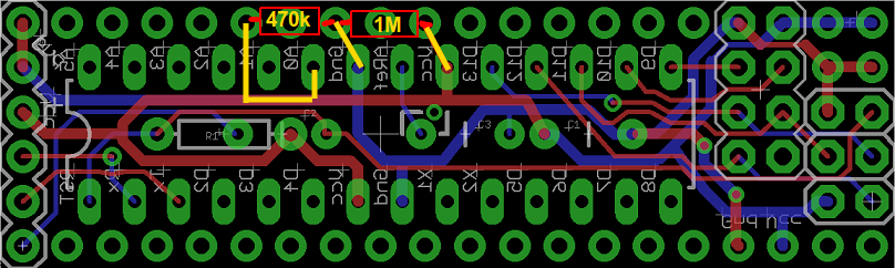
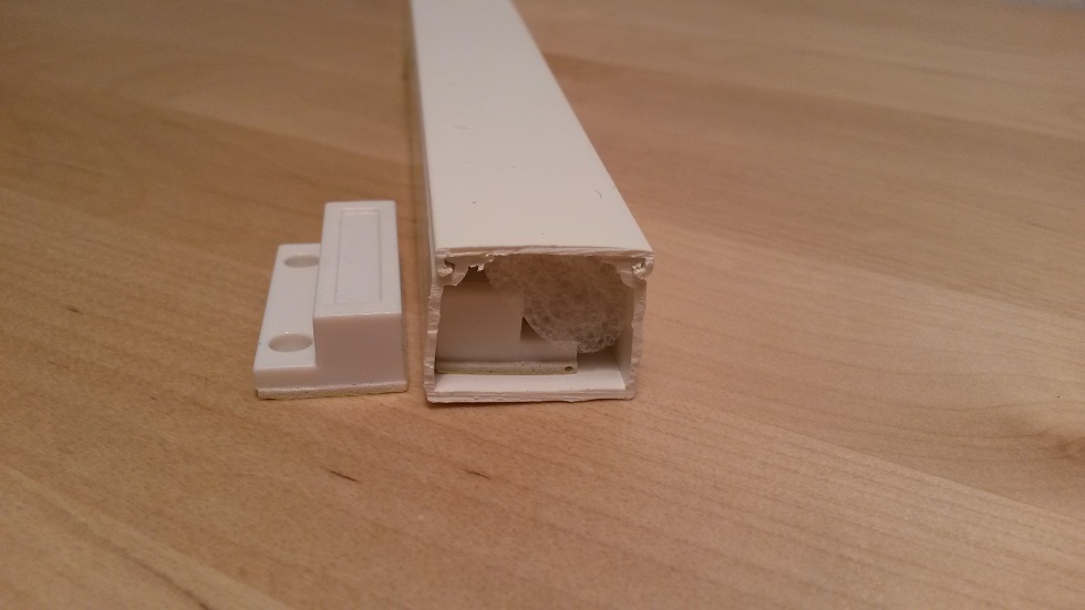
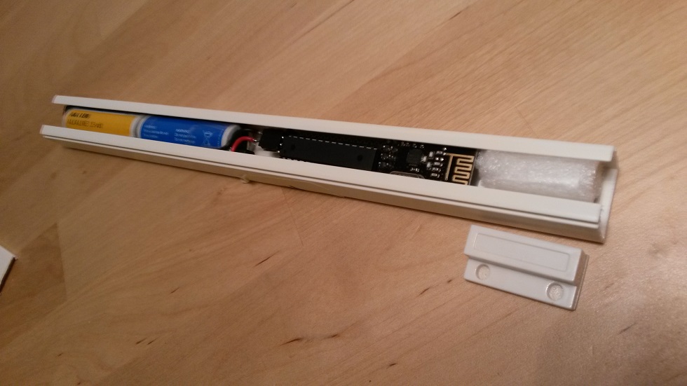
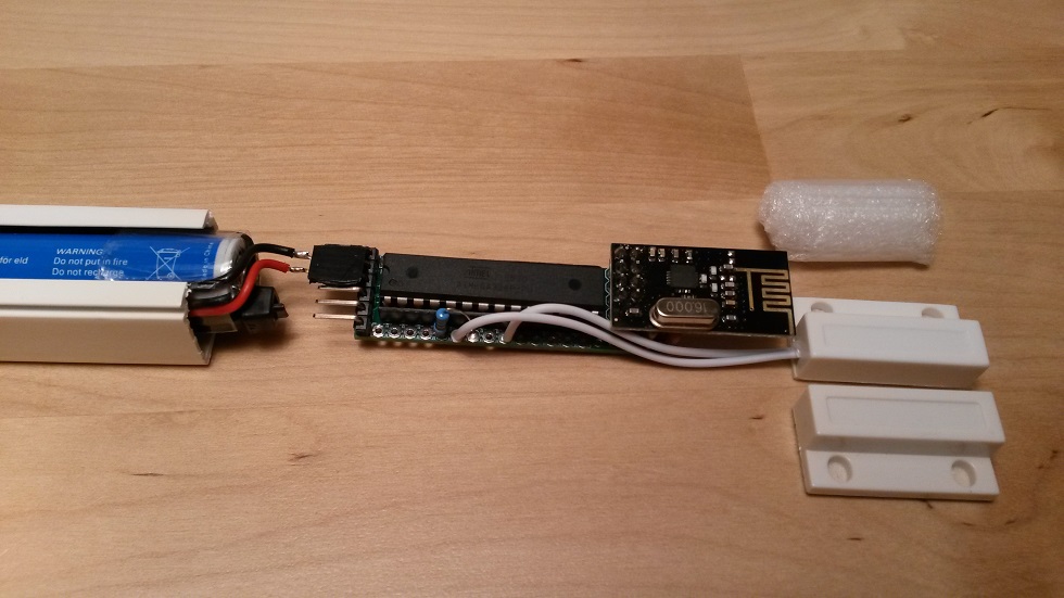
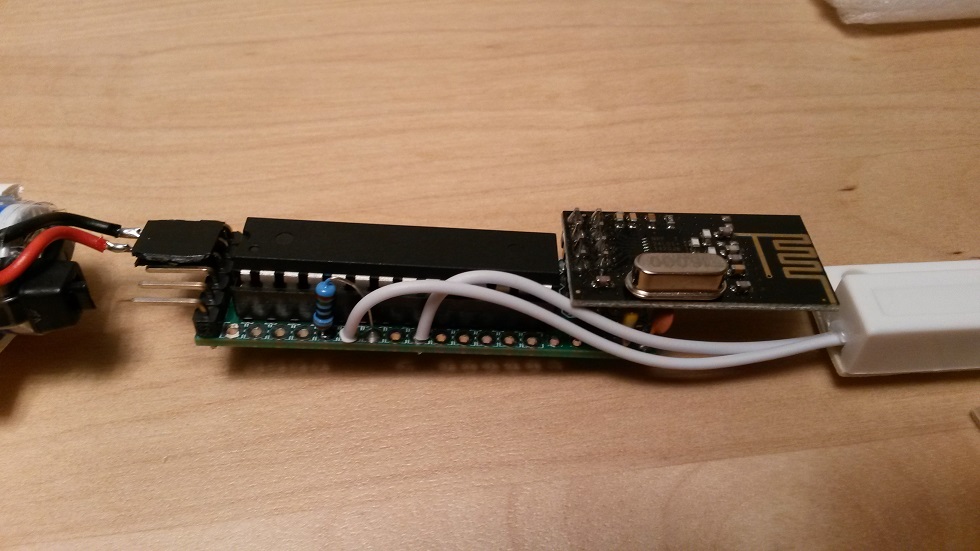
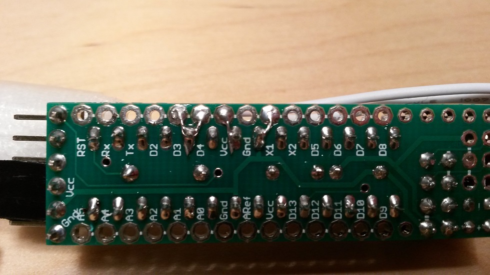
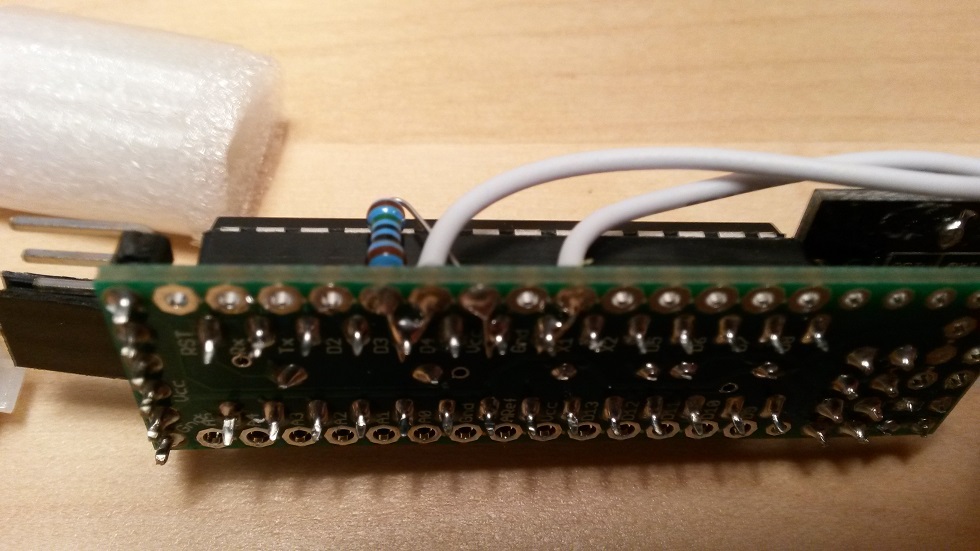

  • Hardware Contributor

    Reed Switch example
    With external 10M pull-up to save battery. The plastic foam is used instead of a fixed mount, for easy disassemble, reflash, battery renewal etc.
    bild1.jpg
    bild2.jpg
    bild3.jpg
    bild4.jpg
    bild5.jpg
    bild6.jpg

    The Sketch

    // EgSlimReed2
    // By m26872, 2015-12-22
    // Interrupt driven binary switch for Slim Node with Reed switch and external pull-up (10Mohm)
    // Inspired by mysensors example:
    // https://github.com/mysensors/Arduino/blob/master/libraries/MySensors/examples/BinarySwitchSleepSensor/BinarySwitchSleepSensor.ino
    
    #include <MySensor.h>
    #include <SPI.h>
    #include <Vcc.h>
    
    #define NODE_ID 5 //12 var senaste "reed-node"-id // 110    // Use static Node_ID  <<<<<<<<<<<<<<<<<<<<<<<<<<<<<<<<<<<<<<<<<<<<<<<
    #define SKETCH_NAME "EgSlimReed"
    #define SKETCH_VERSION "2.0 2015-12-22"
    #define SW_CHILD_ID 5
    #define SW_PIN 3
    #define BATTERY_REPORT_DAY 2   // Desired heartbeat interval when inactive. Maximum heartbeat/report interval is equal to this due to the dayCounter.
    #define BATTERY_REPORT_BY_IRT_CYCLE 10  // Adjust this according to usage frequency.
    #define ONE_DAY_SLEEP_TIME 86400000
    #define VCC_MIN 1.9
    #define VCC_MAX 3.3
    
    int dayCounter = 0;
    int irtCounter = 0;
    uint8_t value;
    uint8_t sentValue=2;
    bool interruptReturn=false;
     
    Vcc vcc;
    MySensor gw;
    MyMessage msg(SW_CHILD_ID, V_TRIPPED);
    
    void setup()  
    {  
      delay(100); // to settle power for radio
      gw.begin(NULL,NODE_ID);
      pinMode(SW_PIN, INPUT);
      digitalWrite(SW_PIN, LOW);    // Disable internal pull-ups
      gw.sendSketchInfo(SKETCH_NAME, SKETCH_VERSION);
      gw.present(SW_CHILD_ID, S_DOOR);  
    }
    
    void loop() 
    {
      if (!interruptReturn) { // Woke up by timer (or first run)
    	dayCounter++; 
    	if (dayCounter >= BATTERY_REPORT_DAY) {
    		  dayCounter = 0;
    		  sendBatteryReport();
    	}
      }
      else {	// Woke up by pin change
    	  irtCounter++;
    	  gw.sleep(50);  	  // Short delay to allow switch to properly settle
    	  value = digitalRead(SW_PIN);
    	  if (value != sentValue) {
    		 gw.send(msg.set(value==HIGH ? 1 : 0));
    		 sentValue = value;
    	  }
    	  if (irtCounter>=BATTERY_REPORT_BY_IRT_CYCLE) {
    		irtCounter=0;
    		sendBatteryReport();
    	  }
      }
    
      // Sleep until something happens with the sensor,   or one sleep_time has passed since last awake.
      interruptReturn = gw.sleep(SW_PIN-2, CHANGE, ONE_DAY_SLEEP_TIME);
    
    } 
    
    void sendBatteryReport() {
    		  float p = vcc.Read_Perc(VCC_MIN, VCC_MAX, true);
    		  int batteryPcnt = static_cast<int>(p);
    		  gw.sendBatteryLevel(batteryPcnt);
    }

  • Hardware Contributor

    Motion sensor example
    As already mentioned; more details to be found here.http://forum.mysensors.org/topic/2715/slim-node-as-a-mini-2aa-battery-pir-motion-sensor

    20160102_001318.jpg


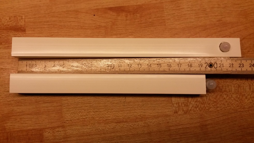
  • do u add these photos and comments to openhardware.io ? they are quite helpful


  • Hero Member

    @m26872 I don't use any I2C pull-ups. All my Si7021/ SHT21 (GY-21) boards include the SDA/SCL pull-ups (and LDO voltage regulator/ level conversion).


  • Hardware Contributor

    @AWI
    Oops, it makes me worried that I completely forgot that this project was in some test stage. Ldo and everything should probably be bypassed, but I wanted to test it first. Post edited. Thanks for noticing!

    And sorry for everyone else if this caused any trouble.

    (It also makes me a little worried about that I have too many ongoing projects right now. ๐Ÿ˜– )


  • @AWI said:

    @m26872 I don't use any I2C pull-ups. All my Si7021/ SHT21 (GY-21) boards include the SDA/SCL pull-ups (and LDO voltage regulator/ level conversion).

    @m26872 said:

    @AWI
    Oops, it makes me worried that I completely forgot that this project was in some test stage. Ldo and everything should probably be bypassed, but I wanted to test it first. Post edited. Thanks for noticing!

    And sorry for everyone else if this caused any trouble.

    (It also makes me a little worried about that I have too many ongoing projects right now. ๐Ÿ˜– )

    Apologies again, so that I understand it, does that mean when adding the mentioned temp sensor nodes I need additional parts?


  • Hardware Contributor

    @rsachoc My mistake and my apology. Unfortunatly I can't even finish and share the resluts from that humidity sensor in a while since I'm leaving for a few weeks holiday.

    Anyway
    @riataman Shows a mod of the GY-21 board in this post. He also link to a board without the LDO and level converter. In any case you wont need the two 4k7 pull-up in my pictures above, only if use the bare chip.


  • What about using a hall effect sensor to detect magnet ?

    I have a door sensor using the same contact sensor, but I also have a hall effect sensor and I hope to test it soon. It is very small compared to the contact sensor.


  • Hello m26872,
    your project is great, and i will order tomorrow a set of PCBs.
    I've done a breadboard setup with the SI7021 according to your schematic and your sketch, which works flawlessly.
    (ATmega328P / SI7021 / NRF24L01 / 2xAA Battery / your 1Mhz bootloader / your Fuse Settings)

    Unfortunately I do not get the current consumption below 2mA.
    What to do to get the power consumption below 10uA and to increase the battery life on a couple of years ?
    Any help is appreciated...


  • Hero Member

    @sensorchecker A power consumption of 2mA is way out of range. Is your sensor entering sleep? Or an ftdi adapter still connected?


  • can i run it on 5V without any problem.

    For the RF433 interface i need 5V so i would like to make one that is powerd by an usb charger.


  • @AWI

    No FTDI Adapter, no LED and nothing else is connected.
    I build the node like the schematic in the first post.
    When i start the sensor node, power consumption is about 16mA.
    After a few seconds (4-5sec) the current goes down to 2mA

    Can you please tell me, how to find out, that the node is in sleep mode
    I have really no idea how to fix that.. but i have to, because i ordered the PCBs today!

    Thanks for your help


  • Hardware Contributor

    @sensorchecker I think you should start with a simple example like the "reed switch sensor" and by looking at the other sketches you should be able to add some debug prints yourself. You only need a high ohm resitor 1M-10M and two pieces of wire to simulate a button or switch.


  • Hardware Contributor

    @arnoldg The nRf24L01+ is rated like 1.9-3.7V. So 5V will probably kill it.


  • Oke, that's tru i didn't think of that.
    but when i use a 5v - 3v power suply in between it could work.


  • @m26872
    I have already tested the "reed switch sensor" and it works fine for me- but with a power consumption of 2mA ...:-(
    Is it possible that i have a problem with the bootloader or the fuses ?
    How can i check that ?
    Usually i use USBASP and avrdude for programming the processors on breadboards.
    Is it also possible to do the whole programming with the arduino IDE ?


  • @sensorchecker did you try changing your nrf ?


  • Contest Winner

    @sensorchecker and @m26872 changing the NRF module did work for me as well.

    I was struggling a lot getting the power consumption down using all the trick and tips as described on the mysensors forum but nothing worked for by battery powered nodes (i have a couple these ).

    I was not able to bring the power consumption down below 2.4 mA (with the NFR mounted) finally i just, for an differnt experiment, i took a "fresh"NRF and just for the fun i measured the current and it was down to 0.05 mA for no reason. They came from the same batch.

    My theory now is that i broke the first radio module during programming of the node, although the FTDI serial module is in 3.3v mode it still measures around 4.5 volt. So the voltage might has damaged my NRF radio a bit (it still communicates).


  • @ahmedadelhosni and @BartE and @m26872 you made my day...!
    Changing the NRF module was the solution, now my power consumption is about 8uA.
    Now waiting for the PCBs and parts to build 10- 15 nodes

    Thank you so much for your help


  • There is no crystal?

    I haven't used Atmega328P as standalone but I have read that you need a crystal.


  • Hardware Contributor

    @flopp There's an internal 8MHz xtal in the uC. Infact often default set to be used by factory "fuse" settings. It's not as ambient condition stable and accurate as an external crystal, but quite good enough for our application.


  • @m26872 thanks


  • What about these pF caps, why not use SMD tantalum instead of Solid electrolyte with legs?

    Or can I use ATmega without caps, since I dont have an external crystal?


  • Hardware Contributor

    @flopp I doubt there are any electrolytes in the pF range seen here. If you mean the pF caps in the example pictures, they are not part of the Slim Node base concept and just a random choice I did for myself. If you mean all the 100nF caps in the base concept, it's a matter of the "smd free" design criteria I apply from time to time.


  • Hardware Contributor

    @flopp ... or if you refer to the standard pair of 22pF caps used when there is an external crystal - no, you wont need them.


  • @m26872 said:

    @flopp I doubt there are any electrolytes in the pF range seen here. If you mean the pF caps in the example pictures, they are not part of the Slim Node base concept and just a random choice I did for myself. If you mean all the 100nF caps in the base concept, it's a matter of the "smd free" design criteria I apply from time to time.

    OK. Yes, I saw that there was cap in pictures.


  • @m26872 said:

    @flopp ... or if you refer to the standard pair of 22pF caps used when there is an external crystal - no, you wont need them.

    OK, perfect


  • Hi together,

    as first i have to say, its a nice node, that you build.
    So i tried to build one. I ordered an atmega 328p. Flashed the bootloader from the forum. This is the boards.txt:

    atmega328_1mhz_4800baud.name=ATmega328 on a breadboard 1MHz internal clock, fast start, 1.8V BOD, 4800baud upload
    
    atmega328_1mhz_4800baud.upload.protocol=arduino
    atmega328_1mhz_4800baud.upload.maximum_size=32256
    atmega328_1mhz_4800baud.upload.speed=4800
    
    atmega328_1mhz_4800baud.bootloader.low_fuses=0x42
    atmega328_1mhz_4800baud.bootloader.high_fuses=0xDE
    atmega328_1mhz_4800baud.bootloader.extended_fuses=0x06
    
    atmega328_1mhz_4800baud.bootloader.file=atmega/atmega328_1b.hex
    atmega328_1mhz_4800baud.bootloader.unlock_bits=0x3F
    atmega328_1mhz_4800baud.bootloader.lock_bits=0x2F
    
    atmega328_1mhz_4800baud.build.mcu=atmega328p
    atmega328_1mhz_4800baud.build.f_cpu=1000000L
    atmega328_1mhz_4800baud.build.core=arduino:arduino
    atmega328_1mhz_4800baud.build.variant=arduino:standard
    
    
    atmega328_1mhz_4800baud.bootloader.tool=arduino:avrdude
    atmega328_1mhz_4800baud.upload.tool=arduino:avrdude
    

    Now i have measured the current draw, and the arduino alone draws 6.8mA (without crystal, nrf ...)
    I tried some sketches, (binaryswitchsleepsensor) but the current is not really gone down.
    The only sketch is this:

    // **** INCLUDES *****
    #include "LowPower.h"
    
    void setup()
    {
        // No setup is required for this library
    }
    
    void loop() 
    {
        // Enter power down state for 8 s with ADC and BOD module disabled
        LowPower.powerDown(SLEEP_8S, ADC_OFF, BOD_OFF);  
        
        // Do something here
        // Example: Read sensor, data logging, data transmission.
    }
    

    With this sketch is the current 0.02mA

    OK, 0.02mA is not bad, but when i read that some of you have few ยตa, i dont understand why the current on my atmega is so "high"

    Can somebody tell me what bootloader is good, wich fuses are good. And maybe what i have to do to get the current so small as possble

    Thank you very much
    Greets Eddie


  • Hardware Contributor

    @meddie I don't really get what you've ruled out in your troubleshooting. Do you "test the arduino alone" using MySensors lib and example sketches? Using Lowpower lib directly works ok as it seems. Next step would be to connect the nRF24L01+ and run some MySensors lib example.

    Ext fuses 0x07 (BOD disabled) instead of 0x06 (BOD 1.8V) could save you a few uA.


  • @m26872 said:

    Do you "test the arduino alone" using MySensors lib and example sketches?

    Yes, on the bredboard is only the atmega 328p. nothing else. Connected to 5v

    Using Lowpower lib directly works ok as it seems.

    Yes using the LowPower lib i came down to 0.01mA current draw.

    Next step would be to connect the nRF24L01+ and run some MySensors lib example.

    Ok, i will try it today evening.

    Ext fuses 0x07 (BOD disabled) instead of 0x06 (BOD 1.8V) could save you a few uA.
    OK, i try this too.

    Thank you very much.
    Greets Eddie


  • ok, i tried to burn with 0x07 Fuse. And i tried to power the atmega with 3.3 v and not 5v.
    Now i came down to 4ยตA in sleep mode with the lowpower sketch.
    When i try to flash a mysensors sketch the the atmega has a current draw 1mA.


  • Hardware Contributor

    @meddie It's still unclear whether you've got the nRF connected and the MySensors example and library fully working (sleeping) before you measure.


  • @meddie If you have a extra nRF try using that, i had a similar issue and i tried replacing the nRF and it came from mA to uA.


  • yes of course, i just connected a nrf to the atmega an uploaded the binaryswitchsleepsensor sketch. Now i have a current draw 95.6ยตA
    But when i take the door contact off the atmega draws only 1.3ยตA
    When the door contact is closed (from 3 to GND) the the current is rising to 95.6ยตA


  • Hardware Contributor

    Makes sense to me. By closing the contact you get a path from 3V3 via the pullup resistor to ground.

    The current is (for a pullup resistor value around 30KOhm) around 100uA.

    Try NOT using the internal pullup resistor of pin D3, and using an external pullup resistor of 1MOhm or more.

    You will see lower current when the contact is closed.


  • ok, i dont have 1mohm here. but i just ordered them. When i get them i will try out and will write here.
    Thynk you very much for your help.
    Great Forum! Great Projekt!
    Greets Eddie


  • Hello,
    This board is GREAT. But why C5 ave to be different from C1 C2 C3 ?


  • Hardware Contributor

    @Pierre-P I haven't verified the benefits of C5, so it's just theoretical. You could probably omit or replace without any significant difference.

    Anyway, the reasons behind are seen in the BOM. 1 - Package (under uC socket). 2 - RF performance (single layer).


  • @m26872 I see it in the BOM. But now, i can't see where it goes (5 hours... I ask a question, and 5 hours later I can't see what i was talking about....)

    C4 is cool for the NRF pic of tension, but -just for information- it could be wherever between 0Vcc and 5Vcc, not necessarily near the NRF ?

    As an electrician, and not an electronician, I don't understand why so many 0.1uF capacitor are needed (but i put them too) as we can see in MySlimNode2-sch.pdf that they are virtually at the same place... ๐Ÿ˜…

    Thanks for the answer !


  • @m26872 I am about to order the v2 version of the board and I have a few questions as I have never ordered PCBs before.
    The defaults on ordering are:
    layers - 2
    thickness - 1.2 mm
    coating - HASL
    stencil - none

    What are these options? I am tempted to just order as-is...for $14 what could I complain about? I am just curious what these other options are for.


  • Hardware Contributor

    @wergeld
    Layers - The board is designed with 2 copper layers (top and bottom) so you can't change that.
    Thickness - Of your taste. Default is well proven but e.g. a little thinner could make it easier when you break the panelizing cuts.
    Coating and stecil - Honestly I've never bothered to look them up. But google is your friend if you put PCB before as keywords.


  • Hello @m26872 it is me again if you do remember me.

    Just wanted to tell you that I ordered the boards 5 weeks ago and it was delivered to Egypt after 2 weeks, and the silly customs requested some security approvals to give me the boards which I couldn't do it till now. Something pathetic which makes me laugh ๐Ÿ™‚

    Can't wait to do my nodes !


  • Hardware Contributor

    @ahmedadelhosni Welcome back! Yes I remember you had to struggle and could not buy common 433MHz remote controlled switches. Makes sense to do diy projects then I guess.
    Hope you get your new nodes running. Please share your result.


  • @m26872 You are right.

    I'll go tomorrow and try to get the approval ๐Ÿ™‚ Well back soon


  • Finally !
    0_1453641891107_1453641880064-1500367089.jpg

    11 pcbs. But I am really angry and feel bad from what happened by DHL.
    I paid 29$ for shipping and here in Egypt i paid stupid fees for customs and several things equal to 38$ !!!!! I dont know wether this is something related to my country Egypt or not ๐Ÿ˜ž

    I' ll try to forget all what I paid when I do my first node.


  • @ahmedadelhosni that really sucks ๐Ÿ˜ž


Log in to reply
 

Suggested Topics

  • 8
  • 3
  • 2
  • 44
  • 2
  • 1

0
Online

11.2k
Users

11.1k
Topics

112.5k
Posts