My Slim 2AA Battery Node
-
Hey im building my first slim node and i wonder if someone has a sketch for 2 reed switches? i have found the sketch for only 1 reed switch in this thread. Im going to use it for my mailbox. How long do u think it can run on 2x aa batteries?
Do i have to add 2x 10M resistors? or doesnt it work with external resistors then using more then 1 reed switch? -
i have wired everything but it wont work for me :( i have solder the 2 reed switch from gnd to d2 and gnd to d3. and ive done the same 2 1m resistors. I can see the node in domotics but no activity then i open and close.
@Eawo
The reed switches need to sit between GND and D2 or D3 as you have connected.The 1M pull up resistors need to connect between Vcc and D2 or D3.
This way D2 or D3 are electrically connected to Vcc when the switches are open (pulled high). When the switches close, D2 and D3 get connected to GND.
-
I only come down to 12µA with one reed switch, 1MOhm pullup, 1Mhz bootloader and the binarySwitchSleepSketch. Measured with two different multimeters. This is nearly ten times higher than in the first posting. Changing all internal pullups to LOW doesn't change anything.
Is there a way to optimize the power consumption or is it "good enough" ?
@rollercontainer For sub 8uA consumption you need to go to "deep sleep" where the internal timers of the processor are disabled. Only wake up on interrupt.
sleep( interrupt1, FALLING, 0); -
I only come down to 12µA with one reed switch, 1MOhm pullup, 1Mhz bootloader and the binarySwitchSleepSketch. Measured with two different multimeters. This is nearly ten times higher than in the first posting. Changing all internal pullups to LOW doesn't change anything.
Is there a way to optimize the power consumption or is it "good enough" ?
@rollercontainer - I just build a slimnode and 13uA is without anything connected what i can reach as well.
For comparison i aim below 100uA when i do this with pro mini and they last around a year with 2xAA so my guess is 13uA is good enough. -
@rollercontainer For sub 8uA consumption you need to go to "deep sleep" where the internal timers of the processor are disabled. Only wake up on interrupt.
sleep( interrupt1, FALLING, 0);@sundberg84: Thanks, so I will stick to my 12µA :-)
@AWI: I am using sleep with Interrupt as in this example:
sleep(PRIMARY_BUTTON_PIN-2, CHANGE, SECONDARY_BUTTON_PIN-2, CHANGE, 0); -
@sundberg84: Thanks, so I will stick to my 12µA :-)
@AWI: I am using sleep with Interrupt as in this example:
sleep(PRIMARY_BUTTON_PIN-2, CHANGE, SECONDARY_BUTTON_PIN-2, CHANGE, 0);@rollercontainer Your sleep looks good. Did you remove this piece of code?
// Activate internal pull-ups
	digitalWrite(PRIMARY_BUTTON_PIN, HIGH);
	digitalWrite(SECONDARY_BUTTON_PIN, HIGH);
Take a look at this thread for a < 1 uA consumption...
-
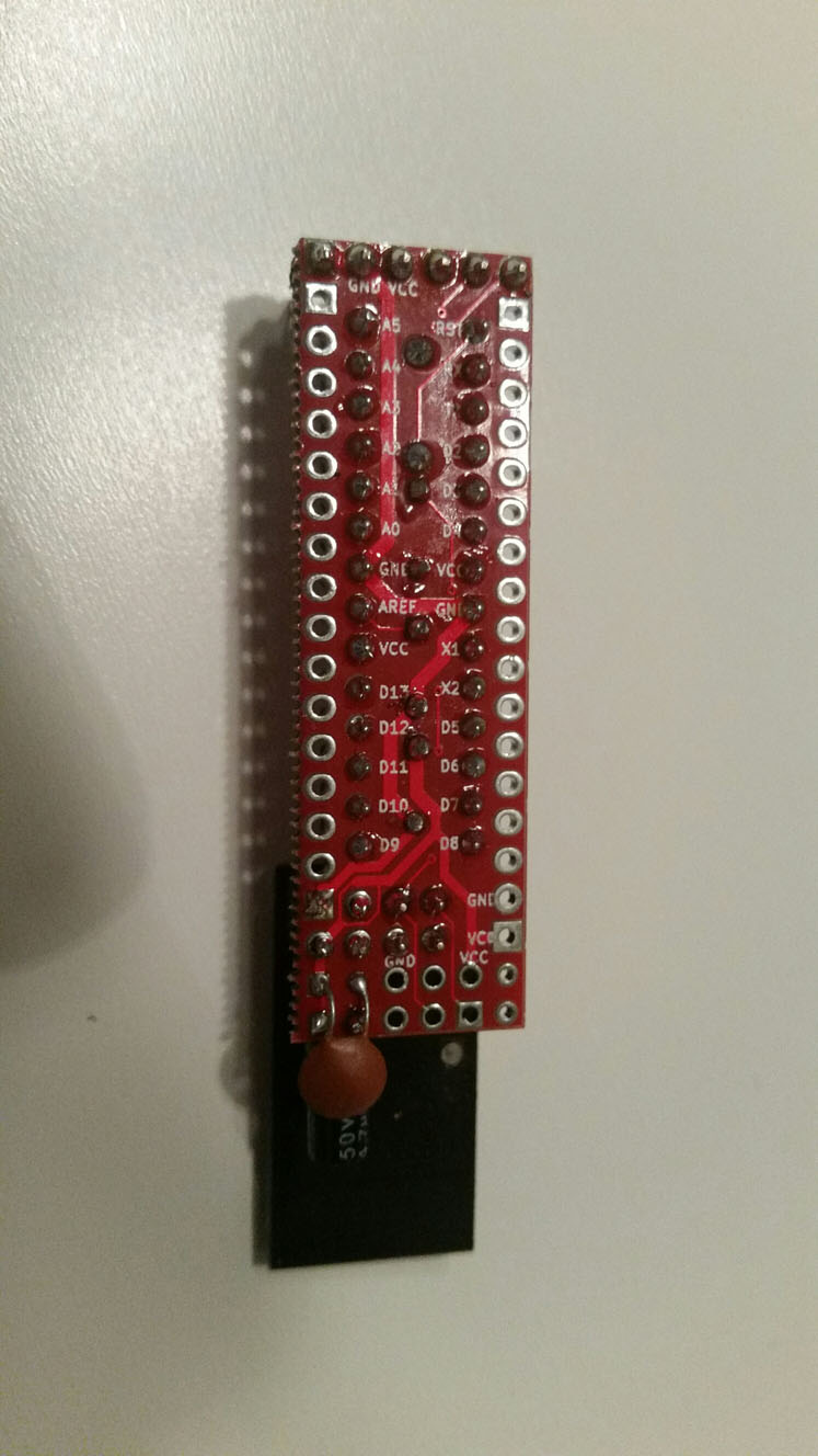
Since a few months I am very interested in Mysensors and this PCB. I have ordered the PCB and components to build some sensors as for a home security system. For experimental purpose I build one on a breadboard and that is working fine.
A few days ago I started to solder the components on the PCB. The firs one is working fine, but the next sensors have an issue with the transceiver. After 3 boards failing I soldered one without the transceiver. Then I tested it by holding the transceiver at the board and it was working fine. After soldering the transceiver again a not working board.I tested one board by pressing another transceiver on top of the soldered one and I saw some communication in MYSController. The ATMega is still working on the breadboard. The PCB and Breadboard are powered by the same batterypack.
Before soldering I tested all the transceivers with my breadboard and they are working fine. I am also using an anti-static bracelet.
What am I doing wrong??
-
Have you desoldered one radio to see if it's back alive again? What's your distance to Gateway? Maybe some filtering or antenna effect by your fingers and breadboard? What if you leave a working radio on the breadboard then just connect it with wires to PCB?
-
Have you desoldered one radio to see if it's back alive again? What's your distance to Gateway? Maybe some filtering or antenna effect by your fingers and breadboard? What if you leave a working radio on the breadboard then just connect it with wires to PCB?
@m26872
Distance is about 50cm. They are both on my desk. If testing then I do not tough the sensor. Just when trien pressing a radio an a non function radio.
I tried to de-solder the radio but did not succeed. Cut the pins, removed them and soldered wires to it. Connected to a new radio. Strange part is that the on very irregular basis message are received in MYSController. Also with a radio which is functioning well on the breadboard -
@m26872
Distance is about 50cm. They are both on my desk. If testing then I do not tough the sensor. Just when trien pressing a radio an a non function radio.
I tried to de-solder the radio but did not succeed. Cut the pins, removed them and soldered wires to it. Connected to a new radio. Strange part is that the on very irregular basis message are received in MYSController. Also with a radio which is functioning well on the breadboard@aneco - 50cm is a big problem for me! Its to close and the node - gw is having a hard time communicating for some reason. I wish I didnt set my gw up in the workplace where i build because every time im testing some node I have to go to the next room. Maybe you could try this?
-
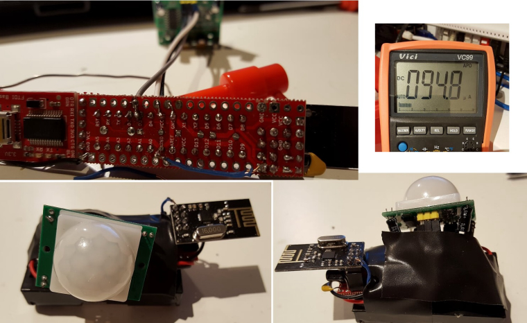
@m26872 - I made this (but with the big motiondec, because my small ones didnt work so well due to clone/copy). Thanks for PCB, instructions and tutorials. Great work!
Node is running at 13uA without motiondetector attached and 90-95uA with the motion dec attached. Im happy with that and ill see how long the batteries last. When my small motion dec arrive I can just switch over.
-
@aneco - 50cm is a big problem for me! Its to close and the node - gw is having a hard time communicating for some reason. I wish I didnt set my gw up in the workplace where i build because every time im testing some node I have to go to the next room. Maybe you could try this?
@sundberg84
The node on the breadboard is on the same desk and same distance to gateway. The same for my first sensor. And both are working well. Only issue with 4 sensors a soldered afterwords.Just remember now that I used for the first sensor other solder. But do not think that this is causing the issue or .....