
My Slim 2AA Battery Node
-
@m26872
thanks again for this great idea and that you developed these fine boards !
And by the way...
As you are using fhem as well...
How do you manage to reset the tripped "1" in Fhem ?
I just added a delay and a gw.send"0" to your sketch :), but using fhem would be more sophisticated actually ...
Thanks@Komaandy said in My Slim 2AA Battery Node:
How do you manage to reset the tripped "1" in Fhem ?
I don't. I just use the last trip time as it's state and then notify (e.g. light or push message) on trip. I think it should be very simple to make a notify with a timer "at" to reset it after a while, if you wish.
-
-
All of the ducting near me is a bit too slim to fit sensors based on this, so I decided to design and print a case instead.
Does the trick nicely, and I also chose to use proper AA battery clips to retain a good connection, as the cable-tie battery assembly wasn't holding well for me!
On the Thingiverse page I have a link to the original OnShape doc.
https://www.thingiverse.com/thing:2418194
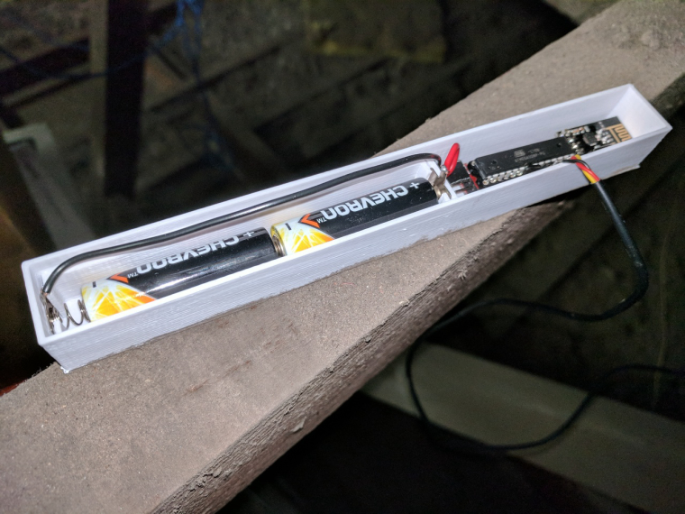
Thoughts, suggestions, etc will be much appreciated!
-
-
Hi
Did anyone make DHT 22 slim node with MySensors 2.0? I created one Node from modified MySenors 2 example...But I get a feeling that it is freezing sometimes (but then again comes back to life).
-
Hi
Did anyone make DHT 22 slim node with MySensors 2.0? I created one Node from modified MySenors 2 example...But I get a feeling that it is freezing sometimes (but then again comes back to life).
@Oliviakrk - I did a test (which works pretty ok) with a DC/DC step up booster attached to D3 -> Vin. This way I could turn the booster on/off with HIGH/LOW from the sketch. This provided 3.3v to my sensors just fine and has been working for a while now. I dont know what will happen when the voltage drops though.
-
@Oliviakrk - I did a test (which works pretty ok) with a DC/DC step up booster attached to D3 -> Vin. This way I could turn the booster on/off with HIGH/LOW from the sketch. This provided 3.3v to my sensors just fine and has been working for a while now. I dont know what will happen when the voltage drops though.
@sundberg84 Thanks. Will try.
-
Hi,
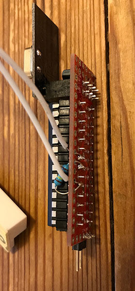
Thank you for all the hard work put into this project. I have built a few door sensor nodes and have some issues. At first I had pull-ups connected as shown in previous pictures but at a logic 1, when there should have been 3.3V there was only roughly half, 1.7V. I am no expert but I take it there has to be a current leak through the D3 pin for this to happen. I have this on all my nodes. I have tried different code but still the same. When I remove the external pull-up the node works properly but instead the batteries run out in a week or so. Have I made a mistake soldering these and maybe shorted something? I have looked at them closely but can't see anything wrong.Does anyone else have this problem? Any tips?
-
-
If I disconnect the battery, there is continuity between D3 and VCC with a resistance of around 20 kOhm. So when the door sensor is shut (no resistance), I connect GND through 20 kOhm to VCC. The current should be 0,165 mA. Too high by reading previous posts but still much less than what I get if I measure. Then I get roughly 18 mA! (Far from a Fluke though but has proven reliable before). Am I misunderstanding things?
I have tried different nodes and sketches with pull-ups both enabled and disabled but I doesn't seem to matter. I have tried different radio modules but still the same, unless I use the bigger! antenna-version. Then the current goes up to 24-25 mA.
I have done/am doing something really wrong although they seem to work just fine. Tomorrow I will try more radio modules to see if I can find any difference.
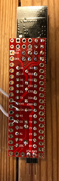
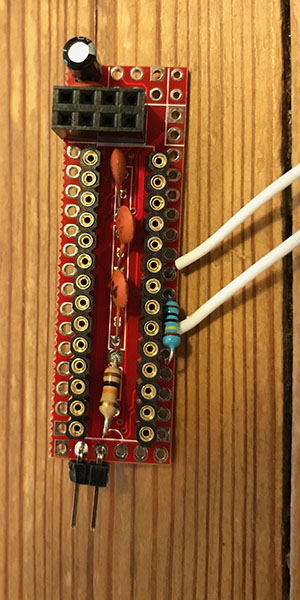
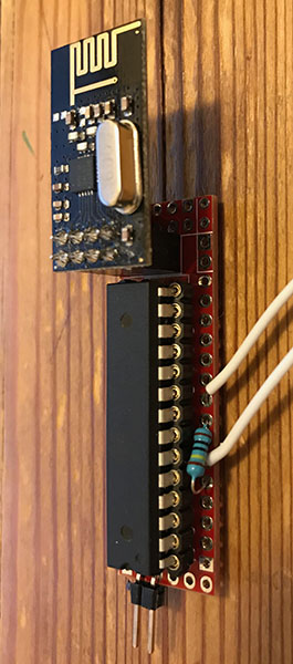
-
If I disconnect the battery, there is continuity between D3 and VCC with a resistance of around 20 kOhm. So when the door sensor is shut (no resistance), I connect GND through 20 kOhm to VCC. The current should be 0,165 mA. Too high by reading previous posts but still much less than what I get if I measure. Then I get roughly 18 mA! (Far from a Fluke though but has proven reliable before). Am I misunderstanding things?
I have tried different nodes and sketches with pull-ups both enabled and disabled but I doesn't seem to matter. I have tried different radio modules but still the same, unless I use the bigger! antenna-version. Then the current goes up to 24-25 mA.
I have done/am doing something really wrong although they seem to work just fine. Tomorrow I will try more radio modules to see if I can find any difference.
@masfak97 It's not clear to me whether you've tried to run it a as pure Arduino, without radio module and without MySensors library in your sketch? (I see that you haven't the serial/FTDI pins soldered - do you use ICSP, pogo-pins or whatever to upload and debug?)
-
I have thought about running it as a pure arduino and to use the debug function, but can't quite get the FTDI to work. I have used this before to upload code to arduino pros. I have a previous node that has all the pins soldered but simply won't be recognized with the USB FTDI. I have also tried switching USB-FTDI but still no luck. Is the FTDI supposed to work if all the pins are there?
I have also bought a USBtinyISP but haven't read up on how to use it.
Currently I install a first boot loader with Nick Gammons sketch running on a UNO connected to a breadboard and the 328. After that has been installed, I install the 8 MHz boot loader by Gert Sanders (thank you of it) and finally upload the code using "Upload using programmer". I currently have no way of reading the serial debug from the node.
I checked the node without the nrf but still power-hungry in the mA.
-
I think you should focus on getting these basic Arduino functions working so you're in control of what's going on. Note that I recently added a few updates to the first post of this thread (under The uC - Software). Read the tutorials and use 8MHz internal clock.
When you get everything running, test your door switch again with a simple Arduino sketch. -
I think you should focus on getting these basic Arduino functions working so you're in control of what's going on. Note that I recently added a few updates to the first post of this thread (under The uC - Software). Read the tutorials and use 8MHz internal clock.
When you get everything running, test your door switch again with a simple Arduino sketch.@m26872
UPDATE 2: There have been reported issues with MySensors 2.x freezing on SlimNodes running at 1MHz, which I've confirmed. Recommended solution when using MyS 2.x, is to use 8MHz (internal) instead.This I can confirm - running at 1 MHz introduced some real oddities with latest MySensors library. Not sure what changed but my nodes definitely freaked out. Will try switching to 8 MHz - hopefully before Irma whacks us here.
-
@m26872
UPDATE 2: There have been reported issues with MySensors 2.x freezing on SlimNodes running at 1MHz, which I've confirmed. Recommended solution when using MyS 2.x, is to use 8MHz (internal) instead.This I can confirm - running at 1 MHz introduced some real oddities with latest MySensors library. Not sure what changed but my nodes definitely freaked out. Will try switching to 8 MHz - hopefully before Irma whacks us here.
-
@wergeld
Same confirmation from my side; 1mhz boot loader doesn't work; dht22 with step up connected does always give NAN. Switching to 8mhz boot loader did the trick.
//@2.2.0-beta -
@kotzer Thanks for sharing. But (AFAIK) the Arduino DHT22 library has never worked at all at 1MHz. And since dht22 doesn't support <3V there's no need for 1MHz anyway.
@m26872
Maybe offtopic, sry, but:
I have Step up at dht22, so it has 3,3v to operate..But I am in wrong topic, it should be your first 2aa sensor ( https://forum.mysensors.org/topic/486/my-2aa-battery-sensor )
This is what I built, and with 1mhz it doesn't work (tried with step up 3,3v and without) this wasted me many hours, because I wanted to save energy as much possible ;) with 8mhz its operating well.
Greets from Germany -
@m26872
Maybe offtopic, sry, but:
I have Step up at dht22, so it has 3,3v to operate..But I am in wrong topic, it should be your first 2aa sensor ( https://forum.mysensors.org/topic/486/my-2aa-battery-sensor )
This is what I built, and with 1mhz it doesn't work (tried with step up 3,3v and without) this wasted me many hours, because I wanted to save energy as much possible ;) with 8mhz its operating well.
Greets from Germany@kotzer Infact I'm actually making a few of my first model too rigth now. I had components left over and despite everyones criticism against the dht22, I find it working very well as long as you deal with the failed readings in the sketch. And, the battery life time was pretty good too. Greets. :+1:
-
I think you should focus on getting these basic Arduino functions working so you're in control of what's going on. Note that I recently added a few updates to the first post of this thread (under The uC - Software). Read the tutorials and use 8MHz internal clock.
When you get everything running, test your door switch again with a simple Arduino sketch.@m26872 I finally got to try your suggestions and loaded the Blink-sketch to my nodes. The power consumtion is then cut to ~4mA. Scrolling back through the forum, I copied the sketch from a user with low power consumption and - Finally - I get an idle comsumtion of 1,9 uA! Connecting the FTDI I can also debug and check for proper function.
I do have another problem I haven't managed to solve; With an UNO and a breadboard I can easily load the bootloader using Nick Gammons sketch and then the sketch with the UNO as ISP. Using the FTDI I can read the serial stream without any problem but I can't seem to load any bootloader or sketches! I keep getting a sync error. I understand the principle of DTR going low and that the capacitor between DTR and reset and the resistor between +5 and reset will make the LOW into a low-pulse and then back to high. With the FTDI I can program a Pro Mini without any problems but it fails constantly with the nodes.
I have no scope so I can't visualize the signal but with the meter I can see that the voltage on the reset is ~3,3v, the resistance between +5 and reset is 10 kOhm and the capacitor reads 83 uF although branded 100uF.
I use Gert Sanders versions of Optiboot at 8Mhz and the one with 38400 NO LED (Thank you for that). I have tried several FTDIs and nodes, checked all connetions, tried to control the reset manually using a breadboard but can't get it to work. I have tried the FTDI at 5v instead (no nRF connected) and tried different boards and speeds. I have tried 1 MHz, 16Mhz.
Is it possible that 83 uF is too small? Any other tips? When building more nodes it would be great to be able to program them without dismantling.
-
@m26872 I finally got to try your suggestions and loaded the Blink-sketch to my nodes. The power consumtion is then cut to ~4mA. Scrolling back through the forum, I copied the sketch from a user with low power consumption and - Finally - I get an idle comsumtion of 1,9 uA! Connecting the FTDI I can also debug and check for proper function.
I do have another problem I haven't managed to solve; With an UNO and a breadboard I can easily load the bootloader using Nick Gammons sketch and then the sketch with the UNO as ISP. Using the FTDI I can read the serial stream without any problem but I can't seem to load any bootloader or sketches! I keep getting a sync error. I understand the principle of DTR going low and that the capacitor between DTR and reset and the resistor between +5 and reset will make the LOW into a low-pulse and then back to high. With the FTDI I can program a Pro Mini without any problems but it fails constantly with the nodes.
I have no scope so I can't visualize the signal but with the meter I can see that the voltage on the reset is ~3,3v, the resistance between +5 and reset is 10 kOhm and the capacitor reads 83 uF although branded 100uF.
I use Gert Sanders versions of Optiboot at 8Mhz and the one with 38400 NO LED (Thank you for that). I have tried several FTDIs and nodes, checked all connetions, tried to control the reset manually using a breadboard but can't get it to work. I have tried the FTDI at 5v instead (no nRF connected) and tried different boards and speeds. I have tried 1 MHz, 16Mhz.
Is it possible that 83 uF is too small? Any other tips? When building more nodes it would be great to be able to program them without dismantling.






Hello! It looks like you're interested in this conversation, but you don't have an account yet.
Getting fed up of having to scroll through the same posts each visit? When you register for an account, you'll always come back to exactly where you were before, and choose to be notified of new replies (either via email, or push notification). You'll also be able to save bookmarks and upvote posts to show your appreciation to other community members.
With your input, this post could be even better 💗
Register Login