My Slim 2AA Battery Node
-
@m26872 I finally got to try your suggestions and loaded the Blink-sketch to my nodes. The power consumtion is then cut to ~4mA. Scrolling back through the forum, I copied the sketch from a user with low power consumption and - Finally - I get an idle comsumtion of 1,9 uA! Connecting the FTDI I can also debug and check for proper function.
I do have another problem I haven't managed to solve; With an UNO and a breadboard I can easily load the bootloader using Nick Gammons sketch and then the sketch with the UNO as ISP. Using the FTDI I can read the serial stream without any problem but I can't seem to load any bootloader or sketches! I keep getting a sync error. I understand the principle of DTR going low and that the capacitor between DTR and reset and the resistor between +5 and reset will make the LOW into a low-pulse and then back to high. With the FTDI I can program a Pro Mini without any problems but it fails constantly with the nodes.
I have no scope so I can't visualize the signal but with the meter I can see that the voltage on the reset is ~3,3v, the resistance between +5 and reset is 10 kOhm and the capacitor reads 83 uF although branded 100uF.
I use Gert Sanders versions of Optiboot at 8Mhz and the one with 38400 NO LED (Thank you for that). I have tried several FTDIs and nodes, checked all connetions, tried to control the reset manually using a breadboard but can't get it to work. I have tried the FTDI at 5v instead (no nRF connected) and tried different boards and speeds. I have tried 1 MHz, 16Mhz.
Is it possible that 83 uF is too small? Any other tips? When building more nodes it would be great to be able to program them without dismantling.
-
@m26872 Thank you for your suggestions. I have now tried them (and many more) but still can't it to work. It's really not a big problem since I can program them using an Uno as ISP instead but it's really annoying that I can't get it to work.
I have checked my chips, they are all at mega328P-PU and I have tried many of them with the same result. I have soldered many nodes, thinking that I didn't make the solder connect through the holes but without any luck. I have tried different sockets to make the connections better and I have traced the entire node without finding any broken connections.
To get the sketch loaded I use Nick Gammons board_programmer with an Uno and use the LilyPad boot loader which enables the internal 8 MHz (Using pin 9 as clock instead of an external crystal). After that I program the Uno with ArduinoISP, set the programmer to Arduino as ISP and upload the sketch with "Burn with programmer" command.
I have switched USB-cable, USB outlet on the mac, breadboards, dupont cables, capacitors (different ceramic but all show too little capacitance), Atmegas and FTDI programmers. I have tried all combinations with 3.3 and 5 v without any luck. Programming Arduino Pros with the FTDI works fine.
I have tried the Mincore and Gert Sanders OptiBoot. I have tried to manually reset the chip connecting the reset pin to ground briefly when programming. I have tried lowering the baud rate to 9600. I have tried to load the Uno bootloader together with a 16 MHz crystal and 2 x 22pf capacitors and then the FTDI. I have tried larger electrolytic capacitors.
Last week, when mimicking the slim node on a breadboard, I managed to get the FTDI to work a few times but can't really say exactly what I did. Now I can't get it to work anymore.
All in all I have spent many hours trying to figure this out but without any luck. My nodes look just like the ones I see in your pictures.
Could it be that the internal 8 Mhz is too unstable to work?
Capacitors being too small? I've seen some reporting that they succeeded with larger...
Bad connection somewhere > momentary voltage drop?
Cheap FTDIs?
Mac USB-power maxing out?
Bad atmegas?Please help me solve this annoying problem.
@masfak97 Wow. You work hard. Of course we must help you. I'm not familiar with your programming method. So that would be my quick wild first guess. I can't read that you've verified the fuse settings? Have tried different startup times e.g?
Do I understand correctly if you're able to send and recieve commands to the Atmega with your FTDI after it is programmed ? -
Hi. I have a problem with my slim node with the sketch "temperature"
with the slim pcb node and a DS18B20 in domoticz it does well the node presentation but neither the S_TEMP child arrives nor does it get any temperature afterwards of course.
but if I mount the same sketch in an arduino nano and with power to 5v it works perfectly.
please help -
Hi. I have a problem with my slim node with the sketch "temperature"
with the slim pcb node and a DS18B20 in domoticz it does well the node presentation but neither the S_TEMP child arrives nor does it get any temperature afterwards of course.
but if I mount the same sketch in an arduino nano and with power to 5v it works perfectly.
please help@Mikepara Please elaborate and post your code. Tell us also about power supply, fuse settings (clock speed) and your troubleshooting steps. See debug-faq-and-how-ask-for-help.
-
-
Hi,
Maybe a silly question, but where did you get the library for the Vcc.h ?
 #include <Vcc.h>
                 ^
compilation terminated.
exit status 1
Error compiling for board ATmega328.
I couldn't find any VCC in the MySensors library set and also doing a search for vcc in the Arduino Library Manager I can't find it either...
[EDIT] : Found it in other thread. Leaving here for reference: https://github.com/Yveaux/arduino_vcc
Thanks
-
Look also at AAA/AA size LiFePO4 as it will need just one cell instead of 2 as the normal alkaline/nimh ones
-
As information for everyone, I suggest that if you get sockets for the ATMEGA, that you get
these:
rather than these:
The reason being that the former have a much wider gap in the middle than the later. Because of that, the .1 puff #104 monolithic multilayer 5.08mm pitch capacitors called for in the BOM fit nicely. If you use the later ones, you will need to remove material from the socket to fit them.
-
I just made a new case for a LiFePO4 magnetic sensor implementation of this. Thanks for the excellent work on this handy node design!
https://www.thingiverse.com/thing:3034907!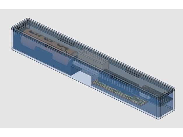
-
Good evening!
I had a bit of a break from this forum (approx 3-4 years...) And just got back into it . I managed to put a bootloader into my 328p-pu chip
can anyone just confirm if it is OK to use this bootloader with the version 2.0 board here.
I understand that it should run at 8Mhz to be stable . so I assumed I could use the bootloader that comes with Arduino IDE ?
I flashed this one onto the chip at the moment and will start to solder some of my boards soon. but would like to be sure that it is correct before I go too far =)
##############################################################
atmega328bb.name=ATmega328 on a breadboard (8 MHz internal clock)
atmega328bb.upload.tool=arduino:avrdude
atmega328bb.upload.protocol=arduino
atmega328bb.upload.maximum_size=30720
atmega328bb.upload.speed=57600atmega328bb.bootloader.low_fuses=0xE2
atmega328bb.bootloader.high_fuses=0xDA
atmega328bb.bootloader.extended_fuses=0x05
#atmega328bb.bootloader.path=arduino:atmega
atmega328bb.bootloader.file=atmega/ATmegaBOOT_168_atmega328_pro_8MHz.hex
atmega328bb.bootloader.unlock_bits=0x3F
atmega328bb.bootloader.lock_bits=0x0F
atmega328bb.bootloader.tool=arduino:avrdudeatmega328bb.build.mcu=atmega328p
atmega328bb.build.f_cpu=8000000L
atmega328bb.build.core=arduino:arduino
atmega328bb.build.variant=arduino:standardrPi 3 - UNO R3 - Mini - Nano - custom
-
Good evening!
I had a bit of a break from this forum (approx 3-4 years...) And just got back into it . I managed to put a bootloader into my 328p-pu chip
can anyone just confirm if it is OK to use this bootloader with the version 2.0 board here.
I understand that it should run at 8Mhz to be stable . so I assumed I could use the bootloader that comes with Arduino IDE ?
I flashed this one onto the chip at the moment and will start to solder some of my boards soon. but would like to be sure that it is correct before I go too far =)
##############################################################
atmega328bb.name=ATmega328 on a breadboard (8 MHz internal clock)
atmega328bb.upload.tool=arduino:avrdude
atmega328bb.upload.protocol=arduino
atmega328bb.upload.maximum_size=30720
atmega328bb.upload.speed=57600atmega328bb.bootloader.low_fuses=0xE2
atmega328bb.bootloader.high_fuses=0xDA
atmega328bb.bootloader.extended_fuses=0x05
#atmega328bb.bootloader.path=arduino:atmega
atmega328bb.bootloader.file=atmega/ATmegaBOOT_168_atmega328_pro_8MHz.hex
atmega328bb.bootloader.unlock_bits=0x3F
atmega328bb.bootloader.lock_bits=0x0F
atmega328bb.bootloader.tool=arduino:avrdudeatmega328bb.build.mcu=atmega328p
atmega328bb.build.f_cpu=8000000L
atmega328bb.build.core=arduino:arduino
atmega328bb.build.variant=arduino:standard@badmannen Welcome back. The good news is that there's now a mysensors bootloader, which is even better because it allows over-the-air firmware updates for the atmega328p: https://www.mysensors.org/about/fota
-
@badmannen Welcome back. The good news is that there's now a mysensors bootloader, which is even better because it allows over-the-air firmware updates for the atmega328p: https://www.mysensors.org/about/fota
@neverdie Alright , that took me a couple of days of fighting with Arduino/Linux/windows/drivers/bootloaders etc etc etc but I got it all running with my updated gateway+repeater-node + mailbox-node. did not try the update function yet but surely it should work. just need one or two more repeater-nodes since I have way to thick cement walls here for this signal.
-
OK I had some fun the last couple of days and actually got something done =D !
Managed to update my gateway and repeater-nodes to latest version and boot-loaded all nodes and future nodes so they are FOTA enabled .
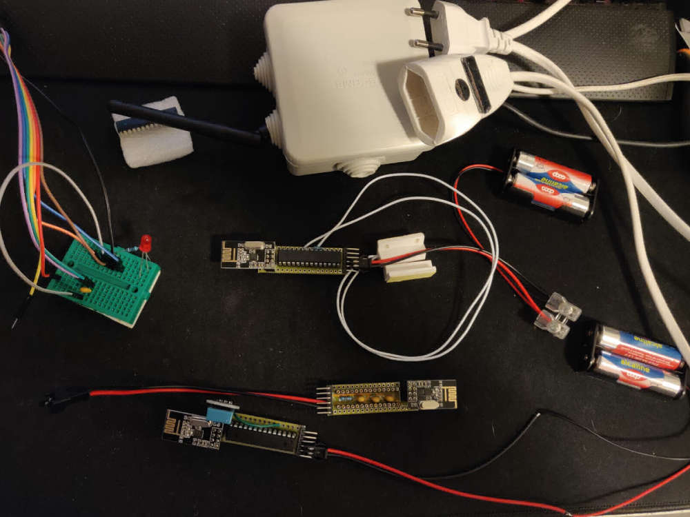
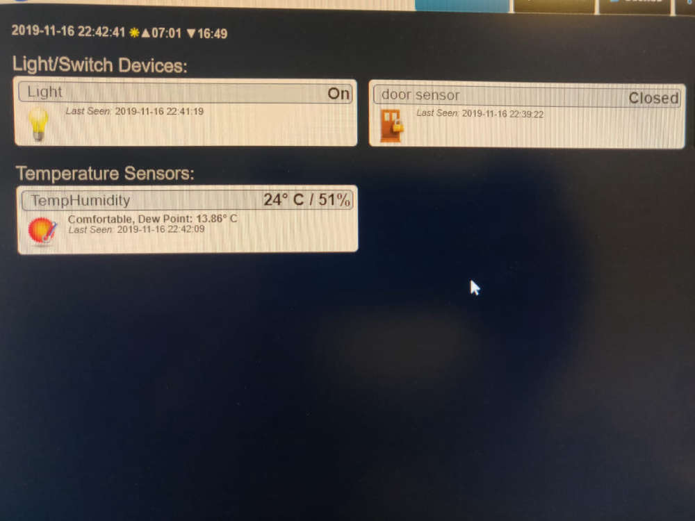
So far I managed to assemble 3 nodes and after a bit of swearing and soldering and de-soldering and re-soldering I got:
1 - DHT11 TEMP / HUM node, on Battery (Slim 2AA) - surprisingly accurate actually2 - DOOR-SWITCH - on Battery (Slim 2AA) - to be used in my mailbox, got the idea from someone here in the forums, so thank you, I don´t remember who it was since I probably read a million posts by now =D
3 - a 220V Relay switch, with the PA LN radio, and works as repeater ( runs on a NANO )
just wanted to say a huge thanks to the MySensors group and all people here on the forum for helping me get started (Had a little break for a couple of years =)
-
Let us know when you get it to FOTA update.