My sensorboard MYS 1.0beta
-
Would like 5 too, if still available.
-
I am soon out of boards to sell. Only got about 15 boards left.
ping @twisted if you still need boards please read your pm.
Because of that have I started ordering components for another batch of boards.
I have also started developing a LED pwm daugtherboard for easy dimming of led strips.
More info on that when first prototype is ready. -
I have ordered 300 more boards yesterday.
As soon as they arrive I hope to have my online ordering page ready.
I also going to sell the boards without components for you that want to source components yourself or are soldering everything directly on board without sockets.
Stay tuned. -
Yes when I stop providing the boards. After that am I going to release it as open hardware.
For now am I selling the boards and the money I making on them are spent on developing new boards. -
@Mrlynx said:
After that am I going to release it as open hardware.
I think it would be a good idea to release the design files right now, as it allows people to get a detailed insight in your design and what they'll receive when ordering.
Furthermore every body can help improve the design, but you'll keep in charge of course.
The whole idea about MySensors (both software and hardware) is to be open so everybody will benefit in the long run. -
I now have 300 boards on my desk and have set up an online ordering system on my page http://www.sa2avr.se/mys-1-1/
After a discussion with @hek have I also released the board files for mys 1.1 on my page. -
Hi
I ve tried to order kit but i had an error message from paypal when i clicked on buy ,..
Does your paypal link correct ?
Thinks -
@ludoarchi Please try again.
I had edited the page to much last night.@Mrlynx
I bought 5 of these as kits from the original order and am very pleased with them. Was a little apprehensive about soldering the small smd's for the 5 to 3.3 volt voltage drop down circuit but with a little practice plus the excellent instruction video referenced above, I was surprised at how easily it can be done. Do recommend using chisel point soldering tip.The boards offer a lot of flexibility for just about any type of sensor--recently completed a temp humidity sensor (which required soldering an additional smd pullup resistor) and also hooked an Oled display to the available A4/A5 pins to display the temp and humidity.
Do have one question. Is a cap needed on the radio? I normally use one but the boards I have built seem to work fine without one (maybe because of the absence of long wire leads and the separate voltage drop down circuit)?
-
@Dan-S.
Happy to hear that the boards work fine. Pictures of your completed sensors would be appreciated.
I recommend using at least one capasistor(C2) to get a stable voltage supply.
C1 is in parallell with a capasistor on the arduino but it should help filtering noise from power supply.http://www.sa2avr.se
-
@Dan-S.
Happy to hear that the boards work fine. Pictures of your completed sensors would be appreciated.
I recommend using at least one capasistor(C2) to get a stable voltage supply.
C1 is in parallell with a capasistor on the arduino but it should help filtering noise from power supply.I did use both the c1 and c2 (1uf) caps you supplied on all of the boards I've constructed. I was referring to an additional decoupling cap directly across ground and 3.3v terminals on the radio which is recommended to be at least 4.7 uf in mysensors.org.
Your boards seem to work fine without an additional cap across the radio, and in one test the board worked better without an additional cap. So unless advised otherwise I will dispense with using any additional cap.
I'll get some pix of my completed sensors.
-
@Dan-S.
Extra cap should only be needed when using radio module with PA+LNA.
data suggest it has a peek current of 115 mA.
I have made a test with a 10uf cap and it looked like it made no difference on a standard radio module. -
What are the exact dimensions of this board?
-
@NotYetRated
50x50 mm -
Here are 2 pix of sensors I built using the boards.
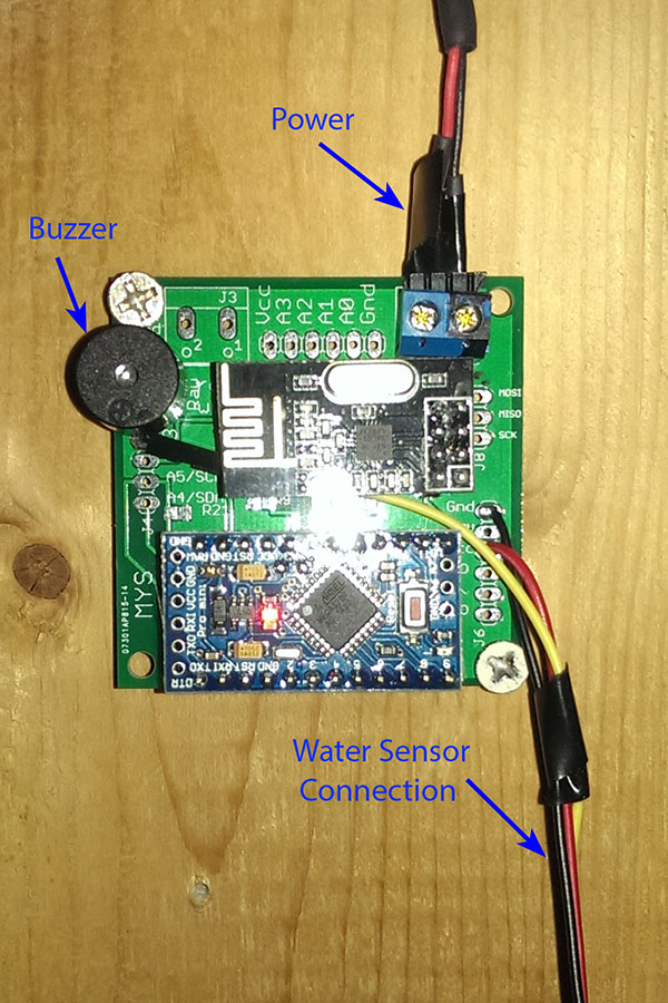
The first is a water sensor/alarm which in addition to triggering the Vera controller, will activate a buzzer as a warning of a water leak in the basement water heater/furnace area.
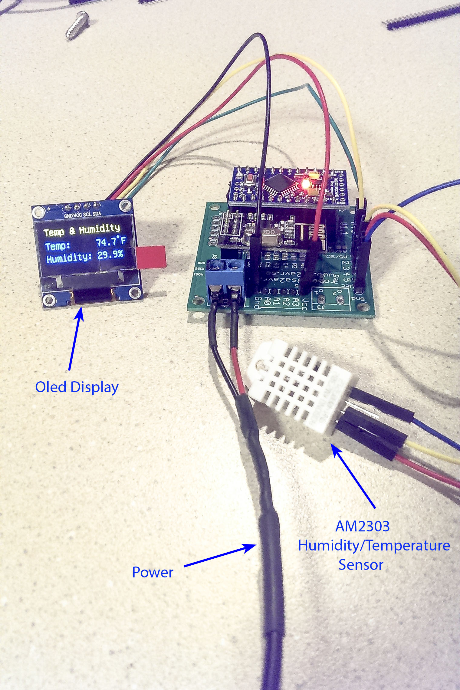
The second is a standard temp/humidity sensor augmented with an Oled display readout. The display and sensor are temporarily hooked up until I decide where/how to mount them.
-
Hi,
I ordered and received 5 kits' and am very happy to have them as last time I spent about 4 hr's soldering on to a prefboard.
But given that I'm nearly a total newbie to electronics I am finding following the assembly instructions nearly impossible.
Any chance somebody did a series of pictures while assembling that they can share? Or maybe a video of the process?
Thanks in advance
Joey