Office plant monitoring
-
Could it be possible to use different power pins? So if you have more than one senor you measure in a sequence?
-
I know that I am a pain in the *ss. But I have tried to change this code to accept more than one power pin.
But I don't know how. I know how to mill a PCB, and lot of other stuff, but programming is not my cup of thee.
I really need to try to study how.
Bot for now, is it anybody who could help me? -
@Lars65 Just a question before things get too crazy: Will you be running your node on battery power? If you will be using wall power you can just power all sensors continuously from Vcc and get rid of the code for turning on and off the sensors, and get rid of all the battery reporting code.
-
Hi!
At the moment do I only have three sensors, and I will be using them on the same arduino. Those will be powered by wall power.
But I have ordered some more sensors, and some of them will be battery powered.
Though both me and my wife often forget to water our plants, do I really like this.
I use Domoticz, and it's easy to get a notification when it's time to water.
You have been really helpfull. Tomorrow will I mill a new PCB, to test this code.
:) -
@Lars65 Just a question before things get too crazy: Will you be running your node on battery power? If you will be using wall power you can just power all sensors continuously from Vcc and get rid of the code for turning on and off the sensors, and get rid of all the battery reporting code.
Hi @mfalkvidd and thank you for your nice work and sketch.
I just have one question about the power pin, I saw on datasheet that the adruino pro mini can handle 40mA max per powerpin. I Have four of these soil moisture sensors but cant find how much current they need... they use a LM393, and the datasheet say 0.4mA..
Did you think than i coul plug all of them on the same powerpin or i need to use your second sketch ?
Thanks in advance ! -
-
Hi Guys!
No I haven't made any measurements.{ 4, 0, 1, // This assumes 2 sensors per pin. First two sensors are powered through pin 4, using analog pins 0 and 1
**5, 2, 3, **// Second two sensors get power from pin 5 and are connected to analog pins 2 and 3
6, 4, 5 // Third set of sensors get power from pin 6 and are connected to analog pins 4 and 5
}
So I did change 4,0,1, to 4,0,. What I saw with this was that I use power pin 4, to the analog input A0. So now have I made it so A0, has powerpin 4, A1 has powerpin 5, and A2 has powerpin 6. -
How did thinks go @Lars65 ?
I thought a bit more about this problem and I think I have come up with a pretty neat solution:
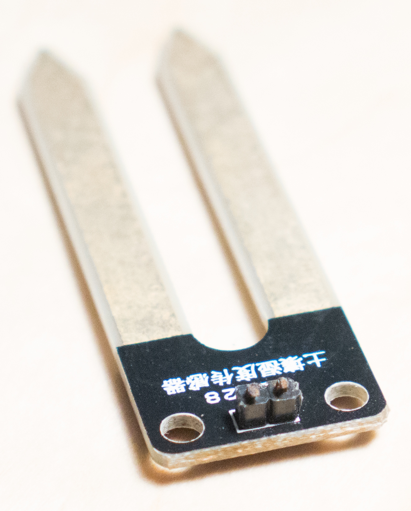
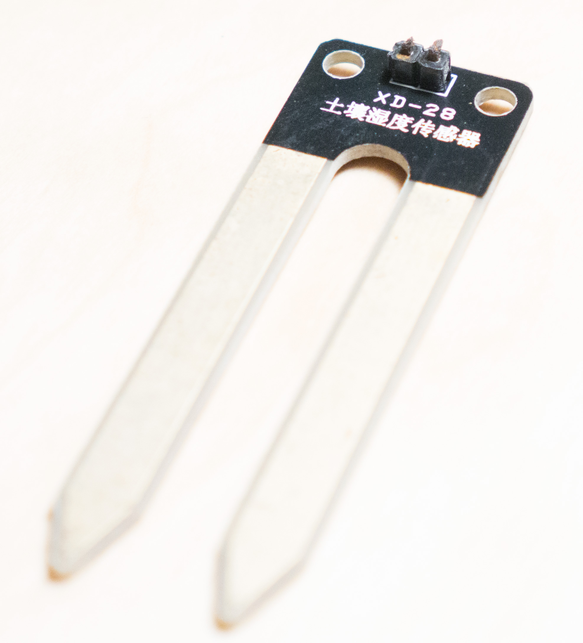
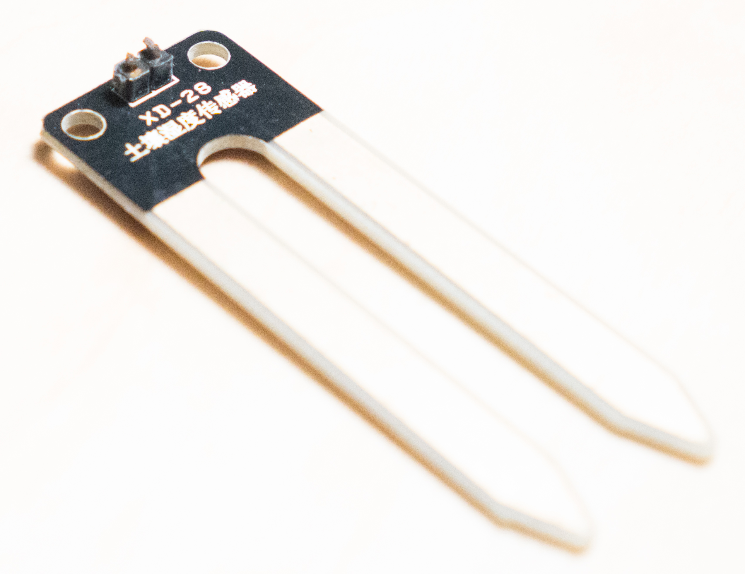
Throw away the chip on the moisture sensor and connect the "pitchfork" directly to the Arduino. Connect one prong to GND and one prong to an analog pin. No power pins are required.
https://codebender.cc/sketch:177182
The chip on the moisture sensor is basically a voltage divider. We get the same thing if we use the internal pull-up resistor on the Atmega processor.
EDIT: This means you can buy just the "pitchforks" really cheap: http://www.aliexpress.com/item/10pcs-Soil-Hygrometer-Detection-Module-Soil-Moisture-Sensor-Probes/2051713873.html -
@mfalkvidd , I think there has been many discussions on how these sensors corrodes over time.
I can see that this node sleeps between the readings and thus reduces corrosion as it only is powered during reading.
However, some threads I've read suggests that you alternate the power, as well, between readings.
Something you might implement in the code?
Also, do you have an estimate on the duration usage on the batteries for one of your plants?
Cheers! -
@Nicklas-Starkel If a measurement is taken once per hour, the sensor will only have power 0,008% of the time.
If corrosion still is a problem, and if the corrosion can be avoided by reversing polarity for every second measurement, I might add it. It would add complexity to the sketch though, and complexity is often the enemy of reliability.Also, for people wanting to use multiple sensors on the same mcu, reversing polarity would cut the possible number of connected moisture sensors in half since it would require two analog pins per sensor.
My estimated battery time on 2xAA for a Mini Pro with removed power led and voltage regulator is 1-2 years.
-
How did thinks go @Lars65 ?
I thought a bit more about this problem and I think I have come up with a pretty neat solution:
Throw away the chip on the moisture sensor and connect the "pitchfork" directly to the Arduino. Connect one prong to GND and one prong to an analog pin. No power pins are required.
https://codebender.cc/sketch:177182
The chip on the moisture sensor is basically a voltage divider. We get the same thing if we use the internal pull-up resistor on the Atmega processor.
EDIT: This means you can buy just the "pitchforks" really cheap: http://www.aliexpress.com/item/10pcs-Soil-Hygrometer-Detection-Module-Soil-Moisture-Sensor-Probes/2051713873.html@mfalkvidd said:
How did thinks go @Lars65 ?
I thought a bit more about this problem and I think I have come up with a pretty neat solution:
Throw away the chip on the moisture sensor and connect the "pitchfork" directly to the Arduino. Connect one prong to GND and one prong to an analog pin. No power pins are required.
https://codebender.cc/sketch:177182
The chip on the moisture sensor is basically a voltage divider. We get the same thing if we use the internal pull-up resistor on the Atmega processor.Hi @mfalkvidd and thank you very very much for your new version of the skecth for moisture sensors, its very clever ! i will test it as soon as possible
-
@Nicklas-Starkel last weekend one of my sensors broke. Both pins were completely corroded and broke just where I connect the dupont wires. I think I will use hot glue to protect the connectors, but I have also added alternating power to my single-sensor sketch. I have this sketch running on three sensors now.
https://codebender.cc/sketch:158460 -
In MySensors lingo, the Arduino is called a sensor. The part that MySensors calls a controller runs on a "real" computer, and gets information from the sensors. The controller usually handles reporting. The documentation at http://www.mysensors.org/about/network can probably give you a good overview.
-
Just some ideas to the corrosion issue (any photos?). If both pins were corroded, it may not be sufficient with polarity switching. Perhaps a simple active cathodic protection system could help. E.g. a +wire limited to a few uA and wrapped with some aluminium foil in the soil near the sensor?
I haven't yet got to it, but the plant monitoring is on pretty high on my list.
-
@Nicklas-Starkel last weekend one of my sensors broke. Both pins were completely corroded and broke just where I connect the dupont wires. I think I will use hot glue to protect the connectors, but I have also added alternating power to my single-sensor sketch. I have this sketch running on three sensors now.
https://codebender.cc/sketch:158460@mfalkvidd
i am using your sketch for indoor plant monitoring but have modified the sleep time to one hour . the problem i am facing is that every alternate humidity reading i get is a 0
like
first reading ------ 67%
second reading ----- 0%
third reading ------65%
fourth reading ------- 0%and likewise
Please Guide
Thanks