Office plant monitoring
-
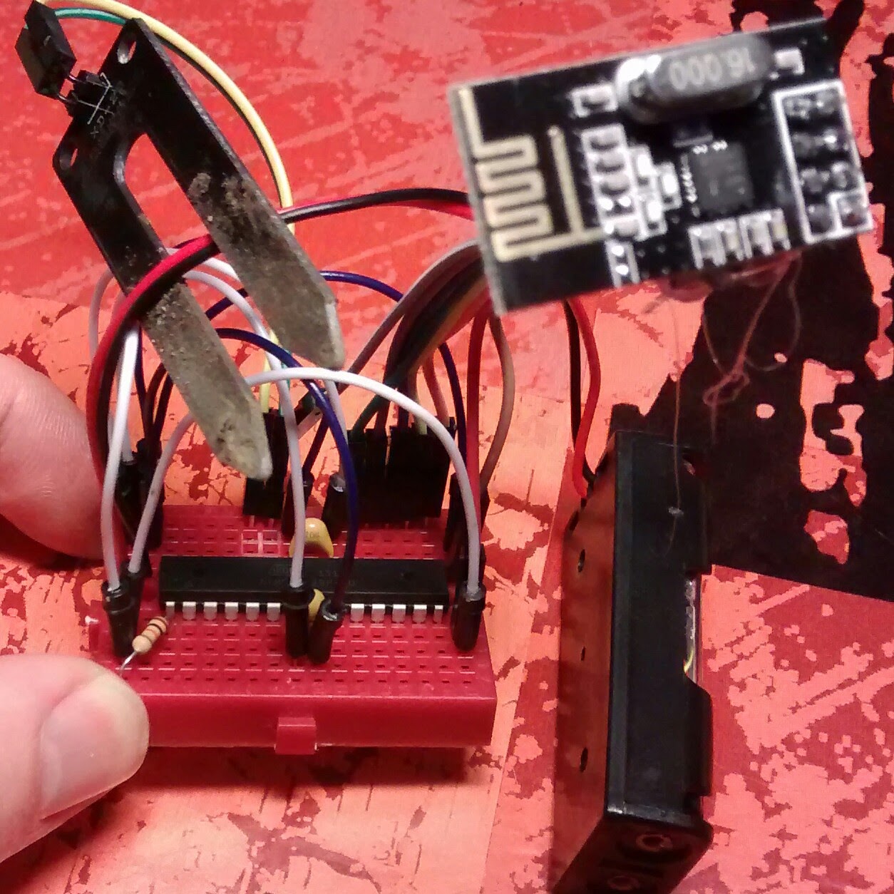
@Nicklas-Starkel last weekend one of my sensors broke. Both pins were completely corroded and broke just where I connect the dupont wires. I think I will use hot glue to protect the connectors, but I have also added alternating power to my single-sensor sketch. I have this sketch running on three sensors now.
https://codebender.cc/sketch:158460@mfalkvidd
i am using your sketch for indoor plant monitoring but have modified the sleep time to one hour . the problem i am facing is that every alternate humidity reading i get is a 0
like
first reading ------ 67%
second reading ----- 0%
third reading ------65%
fourth reading ------- 0%and likewise
Please Guide
Thanks
-
@mfalkvidd
i am using your sketch for indoor plant monitoring but have modified the sleep time to one hour . the problem i am facing is that every alternate humidity reading i get is a 0
like
first reading ------ 67%
second reading ----- 0%
third reading ------65%
fourth reading ------- 0%and likewise
Please Guide
Thanks
-
Hello,
I'm on the same project personally...I using 2 battery... this part should work between 3.3 V and 5V...
finally with 2XAA we only have 3V, and the max value for me is 750 not 1023... did you get 1023 when into the water?
I use a gold plated sensor, and the plug will be into a seal to avoid corrosion and water to go in.
I use a sensbender where I connected on A3 the pin use for the soil moisture sensor.
Could you confirm that change the polarity help to avoid corrosion ???
thanks -
Hello,
I'm on the same project personally...I using 2 battery... this part should work between 3.3 V and 5V...
finally with 2XAA we only have 3V, and the max value for me is 750 not 1023... did you get 1023 when into the water?
I use a gold plated sensor, and the plug will be into a seal to avoid corrosion and water to go in.
I use a sensbender where I connected on A3 the pin use for the soil moisture sensor.
Could you confirm that change the polarity help to avoid corrosion ???
thanks@doblanch said:
the max value for me is 750 not 1023... did you get 1023 when into the water?
I haven't tried in water. I don't care about the absolute value, I just note the reading when the plant needs watering and set a notification for that level. One of my plants needs water at about 70%, another at about 5%. It will vary wildly between different plant types, climate and soil composition.
The value for water will probably vary as well, depending on the water. Distilled water, rain water, tap water, salt water will all have different resistance.
And the value will vary depending on temperature and different Arduinos since the pull-up resistor is inexact.
-
@doblanch said:
Could you confirm that change the polarity help to avoid corrosion ???
thanksNo I can not. All my sensors change the polarity, so I can't tell if there is a difference. You'll have to experiment.
@mfalkvidd ok ; thanks I willl try :-)
-
@doblanch said:
Could you confirm that change the polarity help to avoid corrosion ???
thanksNo I can not. All my sensors change the polarity, so I can't tell if there is a difference. You'll have to experiment.
@mfalkvidd not false :-) I have to make some tries also. I bought a gold platined sensor, I hope that corrosion will be less...
-
@mfalkvidd Thanks for sharing! By looking at your corrosion photos I'd guess galvanic corrosion of pin header.
I think I'll solder my wires instead and put some sealing paint and/or hot glue over it. Polarity switch won't harm, but I'll wait with the cathodic protection for now.
-
@mfalkvidd
its on analog pin A0 -
@mfalkvidd
i have now connected two analog pins A0 and A1 of Pro Mini to the A0 pin of the soil sensor and now i am getting a constant reading of 98% humidity (in water or outside dry).please guide
Thanks
-
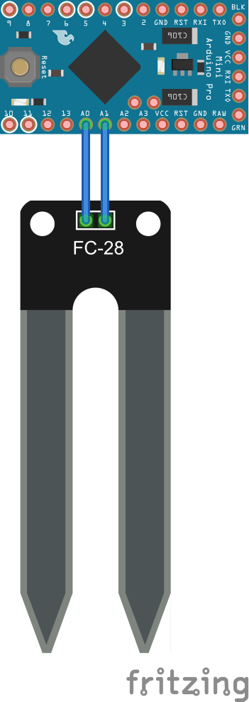
@mfalkvidd
this is how i have connected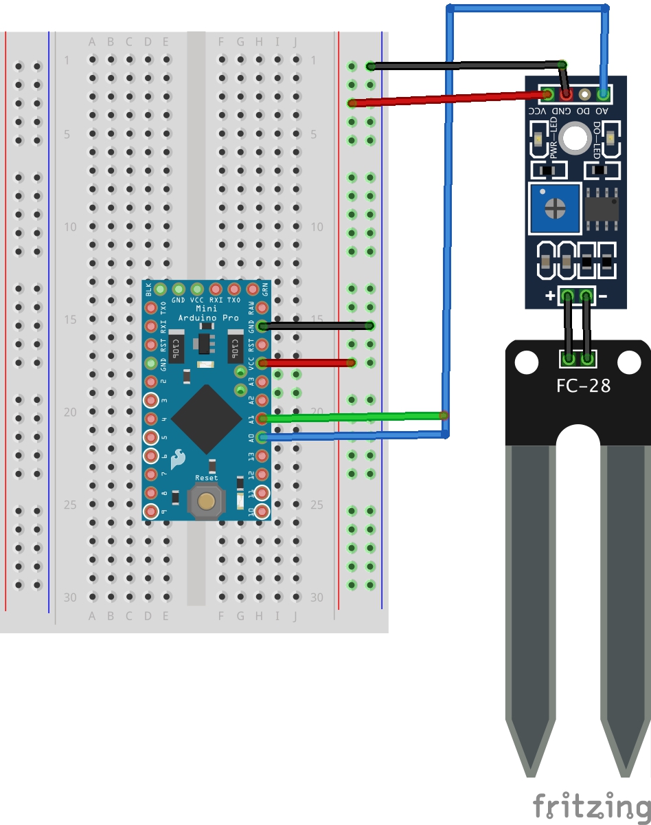
-
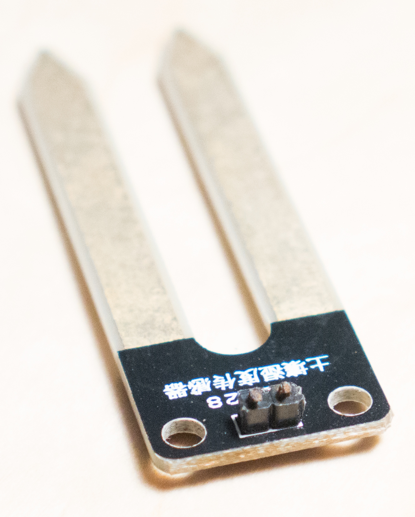
To use the sketch with reverse polarity you need to connect + and - on the prong to A0 and A1 on the Arduino. The chip in the middle is not used.
@mfalkvidd
ok will try -
@Nicklas-Starkel last weekend one of my sensors broke. Both pins were completely corroded and broke just where I connect the dupont wires. I think I will use hot glue to protect the connectors, but I have also added alternating power to my single-sensor sketch. I have this sketch running on three sensors now.
https://codebender.cc/sketch:158460@mfalkvidd said:
@Nicklas-Starkel last weekend one of my sensors broke. Both pins were completely corroded and broke
Did you try to just paint the sensors ?
I've seen that here: https://www.tindie.com/products/miceuz/i2c-soil-moisture-sensor/It doesn't work for me. I go double check the wiring. EDIT: not it's okay now. Great !
But is it possible to use A0-A1, A2-A3, A4-A5 on a atmega328P or there is the same pullup problem ?
-
@Pierre-P said
But is it possible to use A0-A1, A2-A3, A4-A5 on a atmega328P or there is the same pullup problem ?
A0-A5 can be used. A6 and A7 do not have built-in pullup resistors and can not be set high or low. The sketch in http://forum.mysensors.org/topic/2147/office-plant-monitoring/21 mentions that but there have been many revisions and this thread is long so I don't blame you for missing it :)
-
@mfalkvidd said:
@Nicklas-Starkel last weekend one of my sensors broke. Both pins were completely corroded and broke
Did you try to just paint the sensors ?
I've seen that here: https://www.tindie.com/products/miceuz/i2c-soil-moisture-sensor/It doesn't work for me. I go double check the wiring. EDIT: not it's okay now. Great !
But is it possible to use A0-A1, A2-A3, A4-A5 on a atmega328P or there is the same pullup problem ?
@Pierre-P
That i2c thing is painted and works because it's capacitive (it can even sense when your finger is hovering a millimeter or two away from it, like a capacitive touch screen (your phone)). I put one of them into the soil yesterday. If I remember, I will get back regarding results.. I placed it into the same flower as a resistive fork, with the middle chip (so I have some corrosion). -
Hello,
I'm on the same project personally...I using 2 battery... this part should work between 3.3 V and 5V...
finally with 2XAA we only have 3V, and the max value for me is 750 not 1023... did you get 1023 when into the water?
I use a gold plated sensor, and the plug will be into a seal to avoid corrosion and water to go in.
I use a sensbender where I connected on A3 the pin use for the soil moisture sensor.
Could you confirm that change the polarity help to avoid corrosion ???
thanks@doblanch said:
I'm on the same project personally...I using 2 battery... this part should work between 3.3 V and 5V...
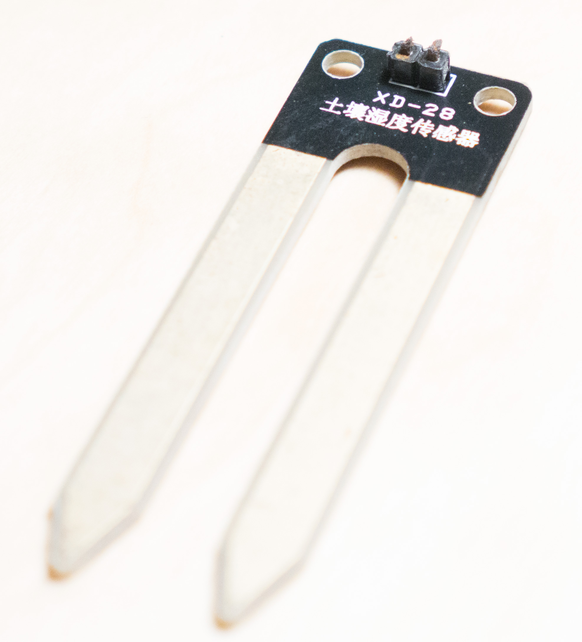
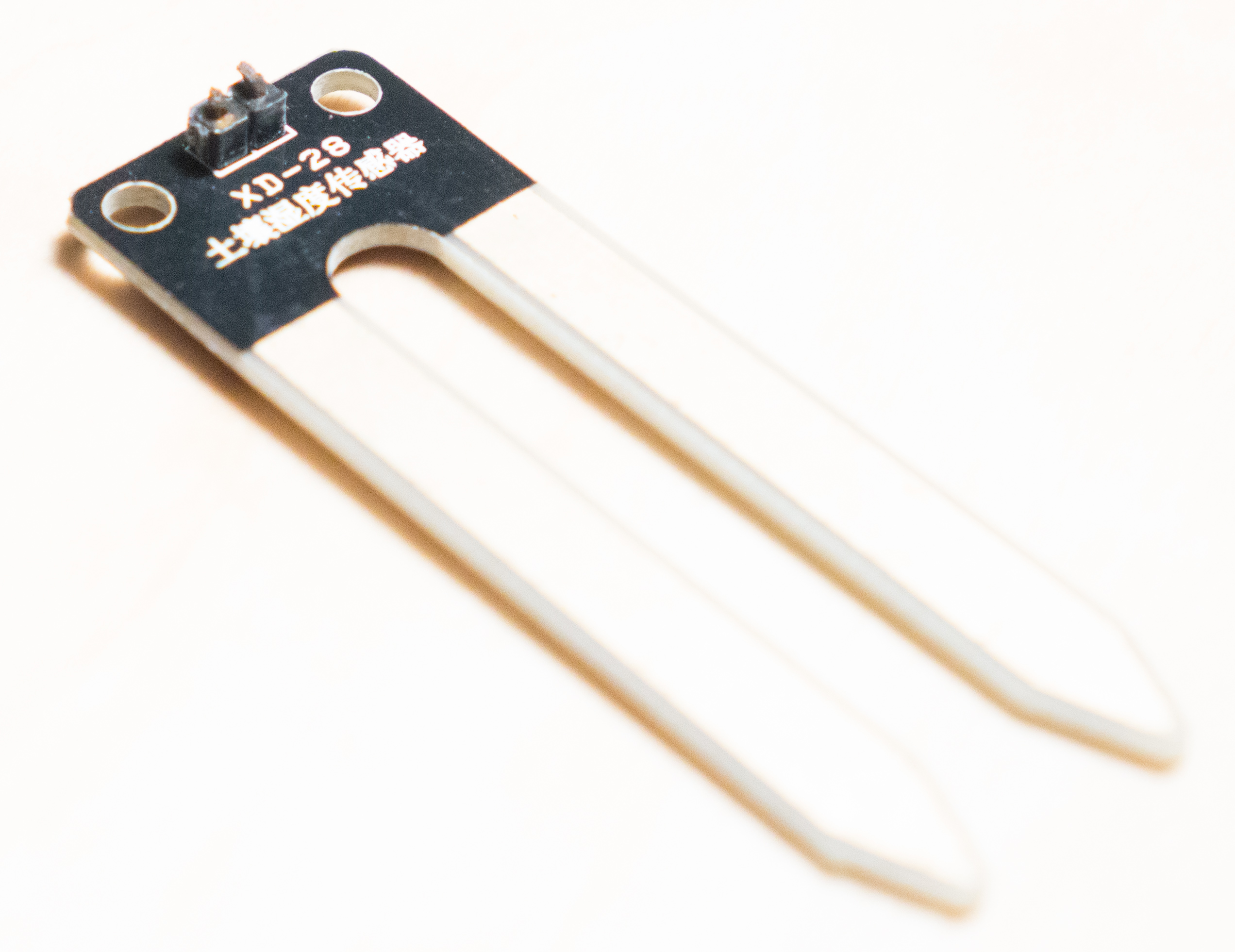
finally with 2XAA we only have 3V, and the max value for me is 750 not 1023... did you get 1023 when into the water?If you have the XD-28 sensor, I think air is about 1023 (so minimal connection). If you put it in water it will be much lower, 300 to 400. 100% water isn't realistic of course and because of that, I get my first reading with the sensor in the air and the second one I initiate with a button press when it's planted and the spot is fully watered.
The button press is just a way to get the different readings for different soil. It does actually read the sensor 200 times and takes a median of that and set the "0" point after that.
I'm trying to measure the centibar which is (apparently, I did not know this a week ago) the right way to measure the soil. Of course, soil temperature has something to do with it also. I'm working on that at the moment.
-
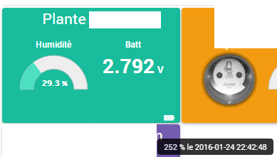
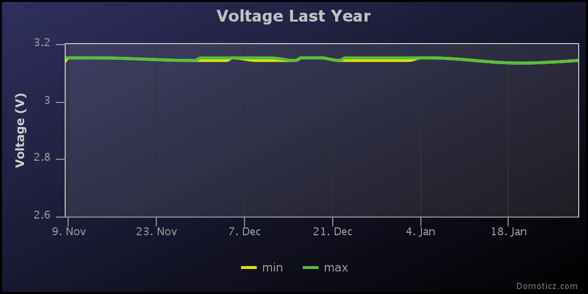
I'm already at 2.73Volts on my two AAA batteries. Is the last sketch a batteries killer ? With a 10 hours sleeping ??