Skip to content
  • MySensors
  • OpenHardware.io
  • Categories
  • Recent
  • Tags
  • Popular
Skins
  • Light
  • Brite
  • Cerulean
  • Cosmo
  • Flatly
  • Journal
  • Litera
  • Lumen
  • Lux
  • Materia
  • Minty
  • Morph
  • Pulse
  • Sandstone
  • Simplex
  • Sketchy
  • Spacelab
  • United
  • Yeti
  • Zephyr
  • Dark
  • Cyborg
  • Darkly
  • Quartz
  • Slate
  • Solar
  • Superhero
  • Vapor

  • Default (No Skin)
  • No Skin
Collapse
Brand Logo
  1. Home
  2. Hardware
  3. rboard - Cheap relay/radio/arduino board ~$10

rboard - Cheap relay/radio/arduino board ~$10

Scheduled Pinned Locked Moved Hardware
57 Posts 15 Posters 28.2k Views 7 Watching
  • Oldest to Newest
  • Newest to Oldest
  • Most Votes
Reply
  • Reply as topic
Log in to reply
This topic has been deleted. Only users with topic management privileges can see it.
  • HomerH Offline
    HomerH Offline
    Homer
    wrote on last edited by
    #21

    @Homer said:

    Which board do I choose when uploading a sketch to this?

    It's all good, I found a website which stated what it was compatible with So I'm moving on :-)

    Now I am just trying to work out how to connect a switch to the A0 pin. There are two pins so is the switch just bridging the two? Sorry, I really am trying to learn this stuff.

    1 Reply Last reply
    0
    • HomerH Offline
      HomerH Offline
      Homer
      wrote on last edited by
      #22

      Ok, looks like I am slowly getting there :-)

      fyi I tried playing around with the above sketch, but it's a no go as Codebender tells me <Bounce2.h> is missing.

      hekH 1 Reply Last reply
      1
      • HomerH Homer

        Ok, looks like I am slowly getting there :-)

        fyi I tried playing around with the above sketch, but it's a no go as Codebender tells me <Bounce2.h> is missing.

        hekH Offline
        hekH Offline
        hek
        Admin
        wrote on last edited by
        #23

        @Homer

        The link above has been updated to point the MySensors codebender location (where Bounce2 is available).

        HomerH 1 Reply Last reply
        0
        • hekH hek

          @Homer

          The link above has been updated to point the MySensors codebender location (where Bounce2 is available).

          HomerH Offline
          HomerH Offline
          Homer
          wrote on last edited by
          #24

          @hek said:

          The link above has been updated to point the MySensors codebender location (where Bounce2 is available).

          Thanks mate. I'll give it ago again soon.

          1 Reply Last reply
          0
          • greglG Offline
            greglG Offline
            gregl
            Hero Member
            wrote on last edited by
            #25

            I used one of these boards for a multi sensor recently.... Temp/Motion and Relay actuator.

            Turns out to be a very tidy solution !

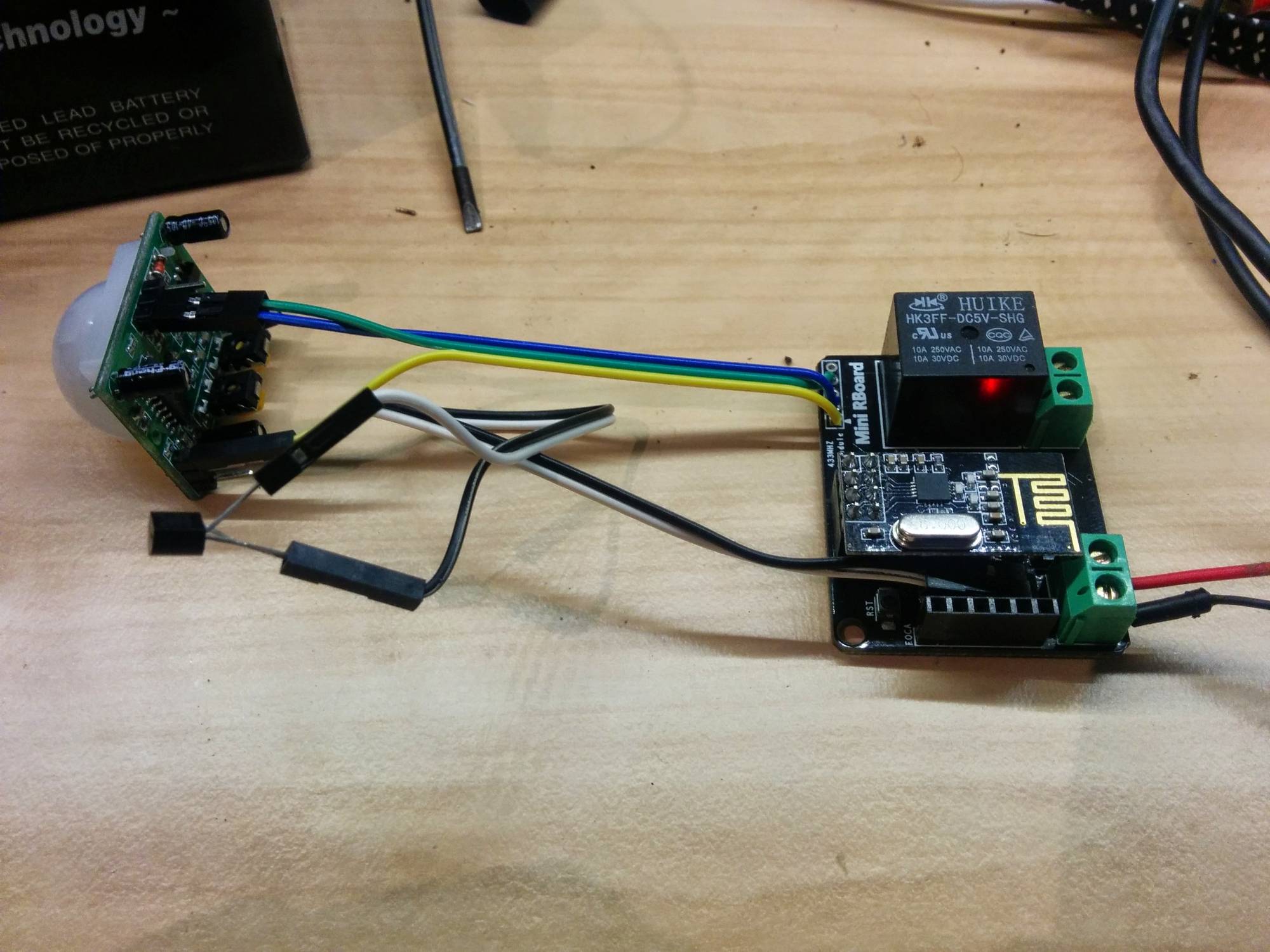
            I'm using the A0 pins connected to a ds18b20 . This is really cute in that the sensor is connected in parasite mode meaning i only need two wires. To do this all you need to do is join pin 1 and 3 to GND and the middle signal wire goes to the A0 ( which is used as D14 ). The rboard also has a 10k resistor from the A0 connection to 3.3v. It works just fine!!

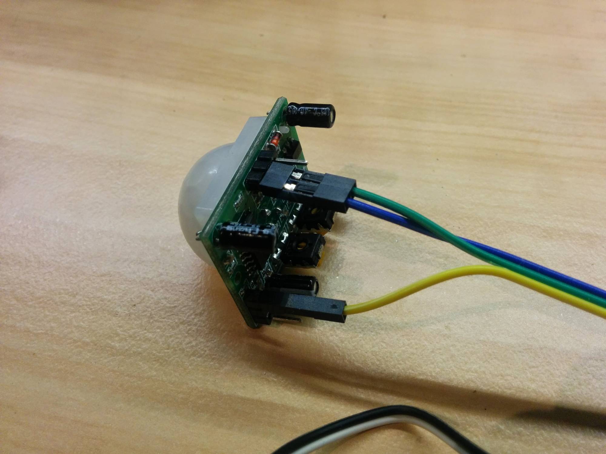
            Then for the PIR, im using the readily available RF433 connections to provide D3, 3.3v and GND. The cute trick here is that even though these PIR's are designed for 5v, they run great on 3,3 v too...you just need to connect it differently! See in the photo where the yellow wire which is the 3.3 v vcc supply connects on the PIR sensor.. Genius!!!

            See here for background on this:
            http://techgurka.blogspot.com.au/2013/05/cheap-pyroelectric-infrared-pir-motion.html

            Do this, feed it 5v ( as relay needs 5v) and you have a tidy little multisensor.

            Here's some pics:
            IMG_20141116_205548.jpg IMG_20141116_205649.jpg IMG_20141116_205633.jpg

            full sketch here https://codebender.cc/sketch:61919

            1 Reply Last reply
            1
            • epierreE Offline
              epierreE Offline
              epierre
              Hero Member
              wrote on last edited by
              #26

              @gregl I've now my rboard, but I have no Foca, so I used my programmer I matched against the pins on the board.

              I choose mini pro 3V3 in the arduino ide but impossible to sync .... is there something I am missing ?

              Also, do you change something on initialization as for the 4 switch version ?

              thanks,

              z-wave - Vera -&gt; Domoticz
              rfx - Domoticz &lt;- MyDomoAtHome &lt;- Imperihome
              mysensors -&gt; mysensors-gw -&gt; Domoticz

              1 Reply Last reply
              0
              • greglG Offline
                greglG Offline
                gregl
                Hero Member
                wrote on last edited by
                #27

                Hi @epierre - I do have a foca and i program as Nano with Atmega328.

                What do you mean "change something on initialization as for the 4 switch version" ?? iirc i also just programmed that as a Nano. is this what you mean??

                Cheers,
                Greg

                1 Reply Last reply
                0
                • epierreE Offline
                  epierreE Offline
                  epierre
                  Hero Member
                  wrote on last edited by
                  #28

                  @gregl so there is no way to program it without a foca ? ;-(

                  I meant about the gw initialization, for the 4 switch rboard you used other parameters, so my wuestion was wether I could use it with default values or extra values.

                  z-wave - Vera -&gt; Domoticz
                  rfx - Domoticz &lt;- MyDomoAtHome &lt;- Imperihome
                  mysensors -&gt; mysensors-gw -&gt; Domoticz

                  1 Reply Last reply
                  0
                  • greglG Offline
                    greglG Offline
                    gregl
                    Hero Member
                    wrote on last edited by gregl
                    #29

                    @epierre - you dont need the foca programmer... any programmer should work as long as you wire correctly - you could even use another arduino.
                    http://www.instructables.com/id/Arduino-Examples-2-Use-an-Arduino-as-a-FTDI-Progr/

                    • make sure you only feed it 3.3v via the programming socket...!

                    For the 4 relay board the CE/CS pins are wired differently to the defaults used by MySensors sketches (9,10) , so you need to tell mysensors library to use (8,9) as this is how they are wired on the Rboard - see the doco ftp://imall.iteadstudio.com/IM120618001_RBoard/DS_IM120618001_RBoard.pdf

                    epierreE 1 Reply Last reply
                    0
                    • greglG gregl

                      @epierre - you dont need the foca programmer... any programmer should work as long as you wire correctly - you could even use another arduino.
                      http://www.instructables.com/id/Arduino-Examples-2-Use-an-Arduino-as-a-FTDI-Progr/

                      • make sure you only feed it 3.3v via the programming socket...!

                      For the 4 relay board the CE/CS pins are wired differently to the defaults used by MySensors sketches (9,10) , so you need to tell mysensors library to use (8,9) as this is how they are wired on the Rboard - see the doco ftp://imall.iteadstudio.com/IM120618001_RBoard/DS_IM120618001_RBoard.pdf

                      epierreE Offline
                      epierreE Offline
                      epierre
                      Hero Member
                      wrote on last edited by
                      #30

                      @gregl nope, I tried and it failed... this is why I asked. One pin is missing, another has another use... I've ordered the foca and I will see.

                      Regarding your PIR Wiring on the picture, you added a 1DS80 right ? I mistakenly thought it was the yellow one ...

                      z-wave - Vera -&gt; Domoticz
                      rfx - Domoticz &lt;- MyDomoAtHome &lt;- Imperihome
                      mysensors -&gt; mysensors-gw -&gt; Domoticz

                      epierreE 1 Reply Last reply
                      0
                      • greglG Offline
                        greglG Offline
                        gregl
                        Hero Member
                        wrote on last edited by
                        #31

                        @epierre - ill see if i can get it to program with another arduino...i dont think there is anything special about the foca....

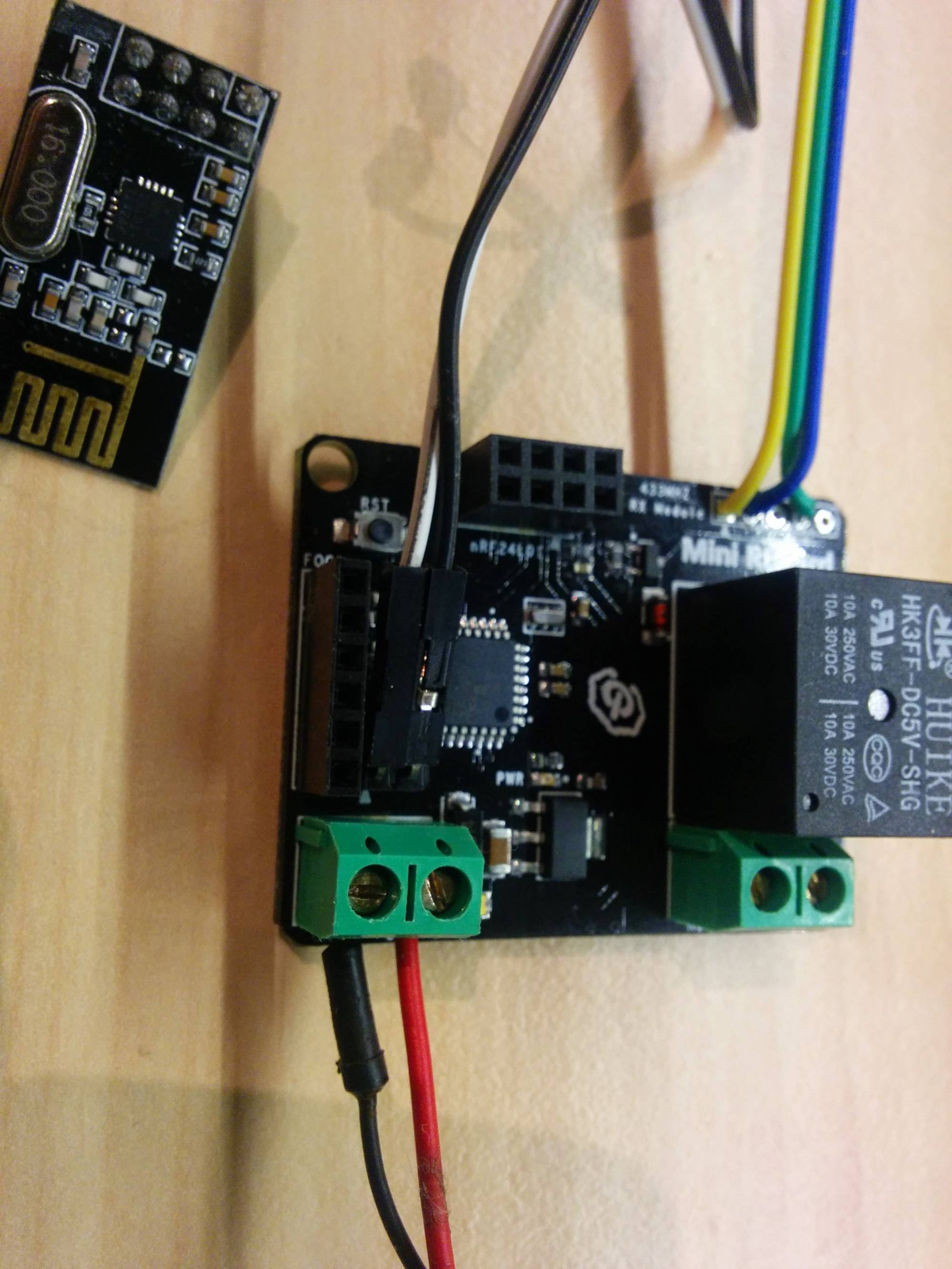
                        so the PIR is wired as such that the VCC provided by the rboard mini ( 3.3) connects to a jumper pin and supplies the PIR module there.... then the PIR quite happliy operates on 3.3!

                        The ds18b20 is connected to the "A0" pin headers hidden under the radio - i just bent them over. On the ds18b20 connect pin 1 and 3 to GND and pin 2 to the A0 ... easy!!

                        1 Reply Last reply
                        0
                        • epierreE epierre

                          @gregl nope, I tried and it failed... this is why I asked. One pin is missing, another has another use... I've ordered the foca and I will see.

                          Regarding your PIR Wiring on the picture, you added a 1DS80 right ? I mistakenly thought it was the yellow one ...

                          epierreE Offline
                          epierreE Offline
                          epierre
                          Hero Member
                          wrote on last edited by
                          #32

                          @epierre Hello,

                          I received the foca and ... RX and TX have to be inverted (RX to TX, and TX to RX), the answer is so simple...

                          @hek a suggestion, would there be a knowledge management section about wiring a special platform to use mysensors ? I think about the Mega or the iboard ? that would be very useful, rather than going through many forum pages ?

                          z-wave - Vera -&gt; Domoticz
                          rfx - Domoticz &lt;- MyDomoAtHome &lt;- Imperihome
                          mysensors -&gt; mysensors-gw -&gt; Domoticz

                          1 Reply Last reply
                          0
                          • D Offline
                            D Offline
                            Dean
                            wrote on last edited by
                            #33

                            Woohoo! After stuffing around with a sketch for my Ethernet Gateway that was never complete to begin with, I have got that working and then made my first sensor using this board!!! L-)

                            1 Reply Last reply
                            0
                            • D Offline
                              D Offline
                              Dean
                              wrote on last edited by
                              #34

                              I've decided to try and do a little more with this board. I initially programmed it to only operate the relay on and off to activate the garage door opener, but it's time for me to push myself lol and do more :-)

                              The problem with how I have it now, is that my Vera 3 doesn't know if the door is open or closed. I was going to add a tilt sensor to the board and have that mounted to the actual door, which I think would mean that it could send a message reporting if it is closed or not. But then I started thinking about the example above which included a switch.

                              So using the relay and the switch to operate the garage door, would that then work to keep Vera 3 in the loop as to whether or not the door is open or closed?

                              If I don't get a response soon, I'll just build it and see what happens :-)

                              Thanks in advance for everyones help! I have already learnt a lot from this site :-)

                              1 Reply Last reply
                              0
                              • greglG Offline
                                greglG Offline
                                gregl
                                Hero Member
                                wrote on last edited by gregl
                                #35

                                Hi Dean,

                                Rather than use a tilt sensor and mount the mini rboard to the moving door, why not just use a reed switch? then you can mount the rboard next to your door controller and run cheap speaker wire to a reed switch and the magnet attached to the moving door..

                                Here is a sketch i use for my garage door using reed switch
                                https://codebender.cc/sketch:44296

                                1 Reply Last reply
                                0
                                • D Offline
                                  D Offline
                                  Dean
                                  wrote on last edited by
                                  #36

                                  Thanks for the tips @gregl!

                                  I am trying to see if I can build this with the sensors that I have, so I can keep my wife happy. So far I am not doing a very good job lol

                                  One of my problems is not knowing which pin is what on this board. I see that you stated above that A0 is D14; how do you find this out?

                                  The other thing I was wondering about is this: If I set up this sensor and garage door to only ever open/close using either my controller sending the message or me pressing a button, then do I even need a reed switch to determine what state the door is in? Can the sketch keep count of the state?

                                  I like your suggested sketch above; in fact I like both examples, and would like to merge the two. The one above with the motion sensor- I don't need that bit, but I like having a temp sensor. What I would like to do is have the temp sensor and instead of the motion sensor I have a switch. Does that sound possible?

                                  My wife has given me the rest of the night off, so I'll see what I can come up with :-)

                                  1 Reply Last reply
                                  0
                                  • D Offline
                                    D Offline
                                    Dean
                                    wrote on last edited by
                                    #37

                                    I just worked out where you get the info regarding what pin is what :-) you have a link in the sketch :-)

                                    1 Reply Last reply
                                    0
                                    • D Offline
                                      D Offline
                                      Dean
                                      wrote on last edited by
                                      #38

                                      lol scratch that last comment.... I have been looking at that PDF and I have no idea how the A0 pin is D14.

                                      1 Reply Last reply
                                      0
                                      • D Offline
                                        D Offline
                                        Dean
                                        wrote on last edited by
                                        #39

                                        Ok what I have done is uploaded the sketch that is exampled above which has the temp sensor. Instead of the motion sensor, I will use a switch, and I'll connect the two wires to the 433 module spot; one wire to GND, and the other to DATA. I am hoping that this will mean that when the switch is activated it will operate.

                                        Gonna go test :-)

                                        1 Reply Last reply
                                        0
                                        • D Offline
                                          D Offline
                                          Dean
                                          wrote on last edited by
                                          #40

                                          lol I ended up with a board that now malfunctions sometimes :-) For some reason the relay began to turn on and off repeatedly, then it stopped working altogether, and now it seems to be working as it should... when my son was running past me the other day which lead to the board falling on the ground, it must have fixed whatever the problem is! In any case, I won't be using that relay for anything too important. I have it in my garage now; it opens and closes the garage door, has a motion sensor and tells me if someone goes into the garage, and it is also sending me the temperature outside. I am happy :-)

                                          So now I want to use another one of these boards to turn a light on, but I want to also have a separate switch which will operate through the board. So basically I am going to use the Garagedoor sketch mentioned above, which is the same as the "Relay with button actuator". I understand what pins I need to assign, but I am a little confused as to how I need to wire up the switch. Am I just completing a circuit, or am I supplying power as the trigger?

                                          RJ_MakeR 1 Reply Last reply
                                          0
                                          Reply
                                          • Reply as topic
                                          Log in to reply
                                          • Oldest to Newest
                                          • Newest to Oldest
                                          • Most Votes


                                          21

                                          Online

                                          11.7k

                                          Users

                                          11.2k

                                          Topics

                                          113.1k

                                          Posts


                                          Copyright 2025 TBD   |   Forum Guidelines   |   Privacy Policy   |   Terms of Service
                                          • Login

                                          • Don't have an account? Register

                                          • Login or register to search.
                                          • First post
                                            Last post
                                          0
                                          • MySensors
                                          • OpenHardware.io
                                          • Categories
                                          • Recent
                                          • Tags
                                          • Popular