rboard - Cheap relay/radio/arduino board ~$10
-
-
@Homer said:
Which board do I choose when uploading a sketch to this?
It's all good, I found a website which stated what it was compatible with So I'm moving on :-)
Now I am just trying to work out how to connect a switch to the A0 pin. There are two pins so is the switch just bridging the two? Sorry, I really am trying to learn this stuff.
-
Ok, looks like I am slowly getting there :-)
fyi I tried playing around with the above sketch, but it's a no go as Codebender tells me <Bounce2.h> is missing.
-
The link above has been updated to point the MySensors codebender location (where Bounce2 is available).
-
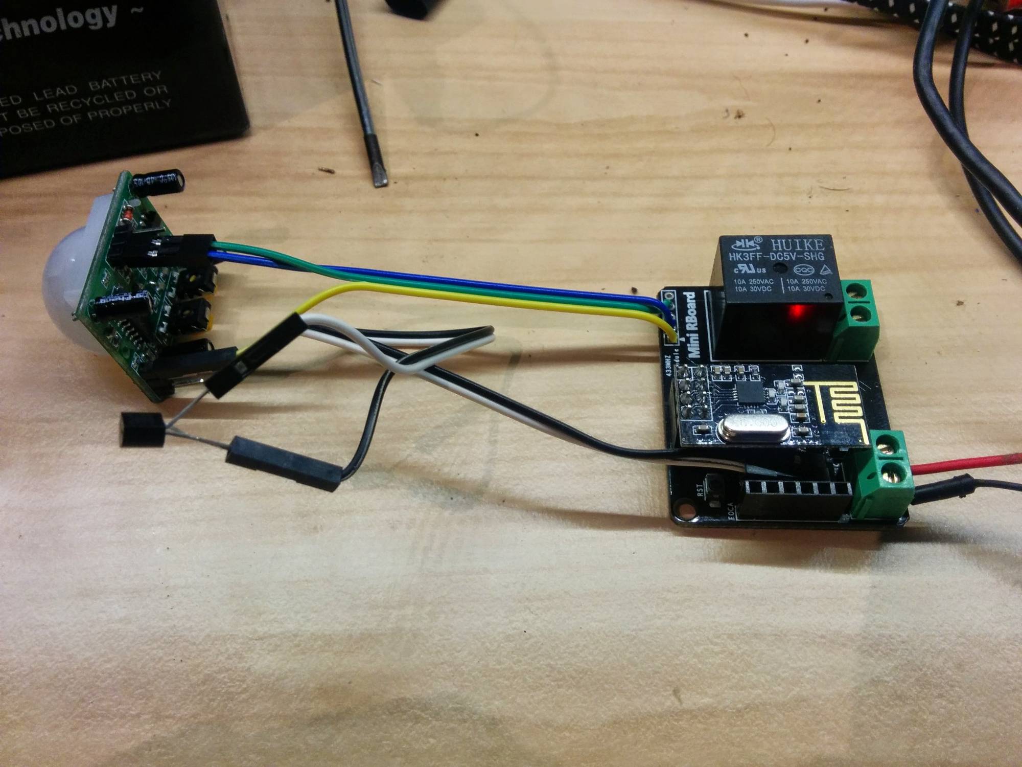
I used one of these boards for a multi sensor recently.... Temp/Motion and Relay actuator.
Turns out to be a very tidy solution !
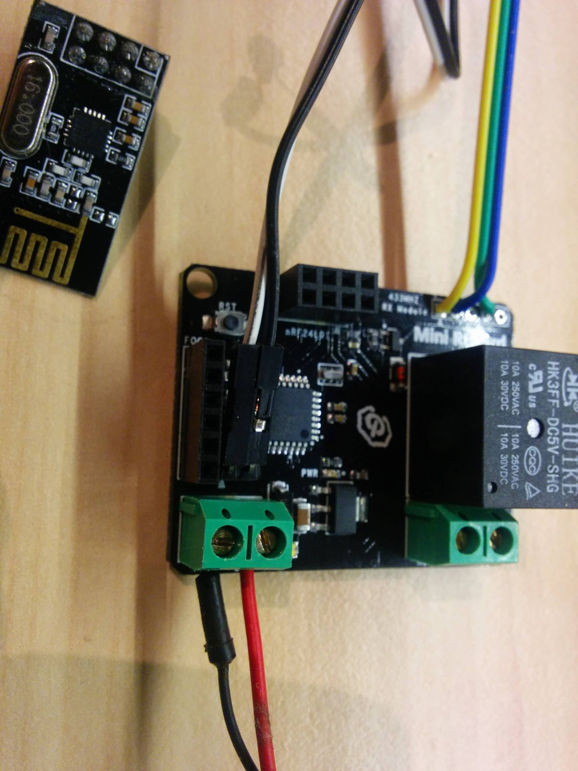
I'm using the A0 pins connected to a ds18b20 . This is really cute in that the sensor is connected in parasite mode meaning i only need two wires. To do this all you need to do is join pin 1 and 3 to GND and the middle signal wire goes to the A0 ( which is used as D14 ). The rboard also has a 10k resistor from the A0 connection to 3.3v. It works just fine!!
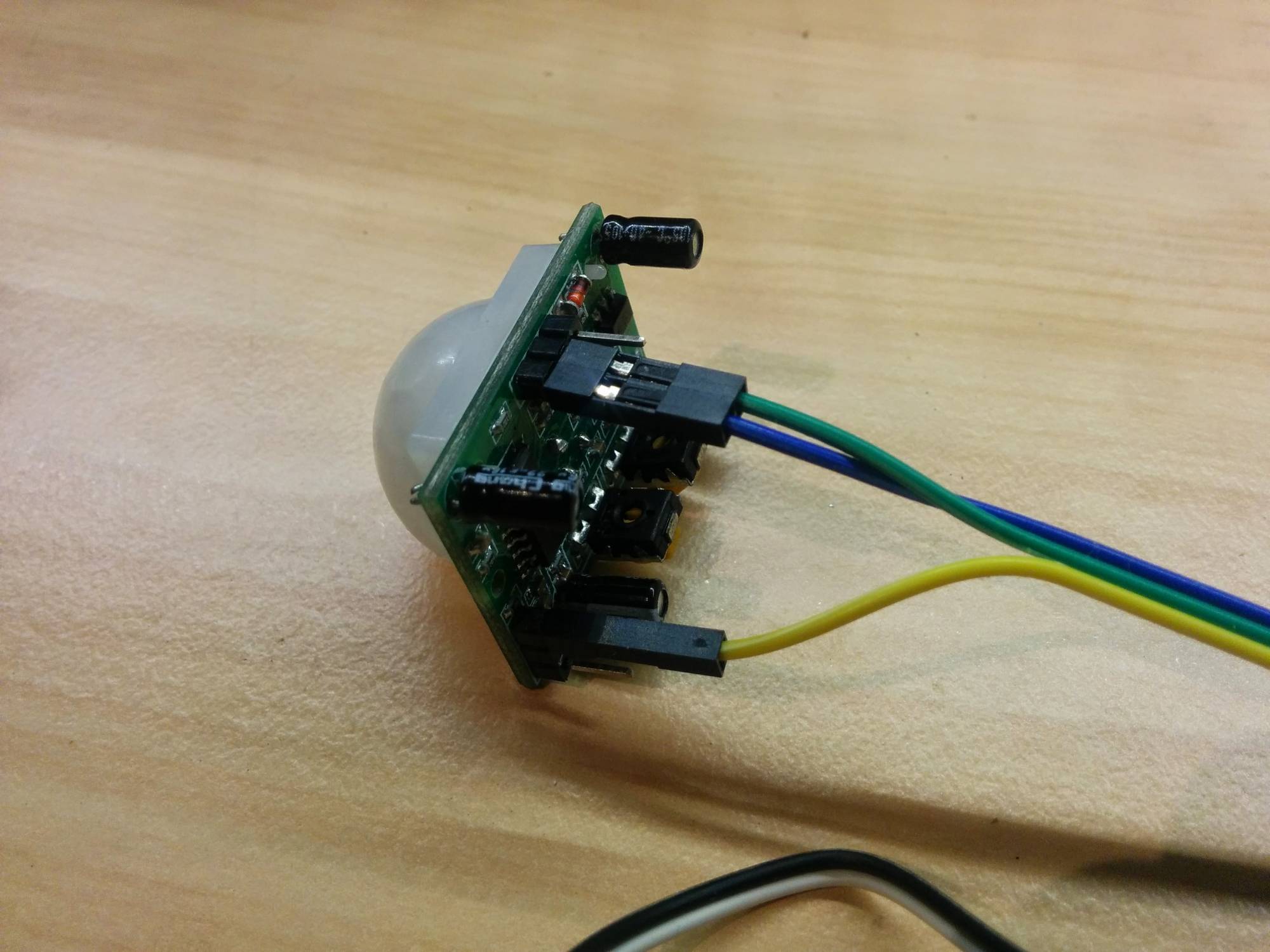
Then for the PIR, im using the readily available RF433 connections to provide D3, 3.3v and GND. The cute trick here is that even though these PIR's are designed for 5v, they run great on 3,3 v too...you just need to connect it differently! See in the photo where the yellow wire which is the 3.3 v vcc supply connects on the PIR sensor.. Genius!!!
See here for background on this:
http://techgurka.blogspot.com.au/2013/05/cheap-pyroelectric-infrared-pir-motion.htmlDo this, feed it 5v ( as relay needs 5v) and you have a tidy little multisensor.
Here's some pics:
full sketch here https://codebender.cc/sketch:61919
-
@gregl I've now my rboard, but I have no Foca, so I used my programmer I matched against the pins on the board.
I choose mini pro 3V3 in the arduino ide but impossible to sync .... is there something I am missing ?
Also, do you change something on initialization as for the 4 switch version ?
thanks,
-
Hi @epierre - I do have a foca and i program as Nano with Atmega328.
What do you mean "change something on initialization as for the 4 switch version" ?? iirc i also just programmed that as a Nano. is this what you mean??
Cheers,
Greg -
@epierre - you dont need the foca programmer... any programmer should work as long as you wire correctly - you could even use another arduino.
http://www.instructables.com/id/Arduino-Examples-2-Use-an-Arduino-as-a-FTDI-Progr/- make sure you only feed it 3.3v via the programming socket...!
For the 4 relay board the CE/CS pins are wired differently to the defaults used by MySensors sketches (9,10) , so you need to tell mysensors library to use (8,9) as this is how they are wired on the Rboard - see the doco ftp://imall.iteadstudio.com/IM120618001_RBoard/DS_IM120618001_RBoard.pdf
-
@epierre - you dont need the foca programmer... any programmer should work as long as you wire correctly - you could even use another arduino.
http://www.instructables.com/id/Arduino-Examples-2-Use-an-Arduino-as-a-FTDI-Progr/- make sure you only feed it 3.3v via the programming socket...!
For the 4 relay board the CE/CS pins are wired differently to the defaults used by MySensors sketches (9,10) , so you need to tell mysensors library to use (8,9) as this is how they are wired on the Rboard - see the doco ftp://imall.iteadstudio.com/IM120618001_RBoard/DS_IM120618001_RBoard.pdf
@gregl nope, I tried and it failed... this is why I asked. One pin is missing, another has another use... I've ordered the foca and I will see.
Regarding your PIR Wiring on the picture, you added a 1DS80 right ? I mistakenly thought it was the yellow one ...
-
@epierre - ill see if i can get it to program with another arduino...i dont think there is anything special about the foca....
so the PIR is wired as such that the VCC provided by the rboard mini ( 3.3) connects to a jumper pin and supplies the PIR module there.... then the PIR quite happliy operates on 3.3!
The ds18b20 is connected to the "A0" pin headers hidden under the radio - i just bent them over. On the ds18b20 connect pin 1 and 3 to GND and pin 2 to the A0 ... easy!!
-
@gregl nope, I tried and it failed... this is why I asked. One pin is missing, another has another use... I've ordered the foca and I will see.
Regarding your PIR Wiring on the picture, you added a 1DS80 right ? I mistakenly thought it was the yellow one ...
@epierre Hello,
I received the foca and ... RX and TX have to be inverted (RX to TX, and TX to RX), the answer is so simple...
@hek a suggestion, would there be a knowledge management section about wiring a special platform to use mysensors ? I think about the Mega or the iboard ? that would be very useful, rather than going through many forum pages ?
-
I've decided to try and do a little more with this board. I initially programmed it to only operate the relay on and off to activate the garage door opener, but it's time for me to push myself lol and do more :-)
The problem with how I have it now, is that my Vera 3 doesn't know if the door is open or closed. I was going to add a tilt sensor to the board and have that mounted to the actual door, which I think would mean that it could send a message reporting if it is closed or not. But then I started thinking about the example above which included a switch.
So using the relay and the switch to operate the garage door, would that then work to keep Vera 3 in the loop as to whether or not the door is open or closed?
If I don't get a response soon, I'll just build it and see what happens :-)
Thanks in advance for everyones help! I have already learnt a lot from this site :-)
-
Hi Dean,
Rather than use a tilt sensor and mount the mini rboard to the moving door, why not just use a reed switch? then you can mount the rboard next to your door controller and run cheap speaker wire to a reed switch and the magnet attached to the moving door..
Here is a sketch i use for my garage door using reed switch
https://codebender.cc/sketch:44296
Hello! It looks like you're interested in this conversation, but you don't have an account yet.
Getting fed up of having to scroll through the same posts each visit? When you register for an account, you'll always come back to exactly where you were before, and choose to be notified of new replies (either via email, or push notification). You'll also be able to save bookmarks and upvote posts to show your appreciation to other community members.
With your input, this post could be even better 💗
Register Login