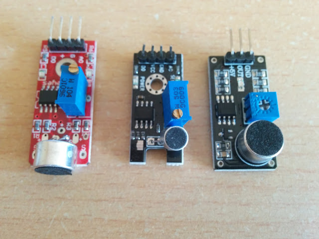
Sound Sensor
-
Hello,
In fact it is a digital on-off output, playing with the potentimeter I saw that... so useless for my project...
-
We can still make it work, tripping when you have a loud noise
-
yes the only way, as a door contact... nut not to measure noise pollution...
-
Not sure what happened to the links in the mysensor store but here is the link to the sound sensor you need, make sure it is the one that has 4 pins, with analog output as an option.
-
Not sure what happened to the links in the mysensor store but here is the link to the sound sensor you need, make sure it is the one that has 4 pins, with analog output as an option.
@wmylionel yes I know this is my fault, I tried to order from one vendor rather to have several parcel, and lacking experience I did not check about this... nor about the wrong China Exports logo... experience come to a price...
z-wave - Vera -> Domoticz
rfx - Domoticz <- MyDomoAtHome <- Imperihome
mysensors -> mysensors-gw -> Domoticz -
@wmylionel yes I know this is my fault, I tried to order from one vendor rather to have several parcel, and lacking experience I did not check about this... nor about the wrong China Exports logo... experience come to a price...
-
@Yveaux the CE marking but C touching the E, without space... it is not Conformité Européenne but China Export... no warranty to comply in European space... be aware...
see wikipedia
Anyway, do you know a way to solder something to have access to something analog on it ?
z-wave - Vera -> Domoticz
rfx - Domoticz <- MyDomoAtHome <- Imperihome
mysensors -> mysensors-gw -> Domoticz -
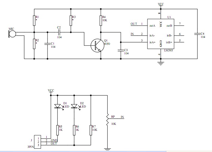
@epierre Hard to say without a schematic... Seems to be something like this: http://yourduino.com/sunshop/images/products/SoundSensorDiagYW-700.jpg
You can try to connect to the analog input of the comparator (pin 3 of LM393) and see if it brings anything, but only if your module is similar ofcourse...
http://yveaux.blogspot.nl
-
@epierre Hard to say without a schematic... Seems to be something like this: http://yourduino.com/sunshop/images/products/SoundSensorDiagYW-700.jpg
You can try to connect to the analog input of the comparator (pin 3 of LM393) and see if it brings anything, but only if your module is similar ofcourse...
@Yveaux Hello I'm trying to compile a sketch using TIMSK, but to use it on an atm 128, I would need either timex8 or timex128 which only comes through an avrlib.
This is where I am lost, I have an avrlib on my disk, should I replace it with the full one ? how can I manage that ?
thanks,
z-wave - Vera -> Domoticz
rfx - Domoticz <- MyDomoAtHome <- Imperihome
mysensors -> mysensors-gw -> Domoticz -
@Yveaux Hello I'm trying to compile a sketch using TIMSK, but to use it on an atm 128, I would need either timex8 or timex128 which only comes through an avrlib.
This is where I am lost, I have an avrlib on my disk, should I replace it with the full one ? how can I manage that ?
thanks,
-
@epierre I have very little time, but sharing the sketch might help to make your problem clear...
@Yveaux thanks, here it is:
http://davidegironi.blogspot.fr/2014/02/a-simple-sound-pressure-level-meter-spl.html
z-wave - Vera -> Domoticz
rfx - Domoticz <- MyDomoAtHome <- Imperihome
mysensors -> mysensors-gw -> Domoticz -
@epierre Had a quick look at the code. Seems the TIMSK stuff is just for timing the ADC samples at regular interval; the TIMER1_OVF_vect sets a flag (audioget_takesample) which is scanned for in the audioget_getsamples() function.
Exactly the same behavior you can get by waiting using delay() or delayMicroseconds(), and then get the sample.
That's probably easier then getting the raw timer stuff going. -
Since @hek is interrested, I'm revivind this post with several microphone available out there, in fact impossible to know if these use real electet ones...
@BulldogLowell I've seen you've participated here http://forum.arduino.cc/index.php?topic=208520.15 but do you think this was the good solution ? if you go through http://davidegironi.blogspot.fr/2014/02/a-simple-sound-pressure-level-meter-spl.html the questions is open...
z-wave - Vera -> Domoticz
rfx - Domoticz <- MyDomoAtHome <- Imperihome
mysensors -> mysensors-gw -> Domoticz -
Hmm.. not super easy to calculate an actual sound "pollution" value or do dB calculations using this I guess.
Hmm.. Adafruit using a sample window in their example.
https://learn.adafruit.com/adafruit-microphone-amplifier-breakout/measuring-sound-levels
-
Since @hek is interrested, I'm revivind this post with several microphone available out there, in fact impossible to know if these use real electet ones...
@BulldogLowell I've seen you've participated here http://forum.arduino.cc/index.php?topic=208520.15 but do you think this was the good solution ? if you go through http://davidegironi.blogspot.fr/2014/02/a-simple-sound-pressure-level-meter-spl.html the questions is open...
@epierre I have ordered almost any kind of sound sensor on aliexpress for my washing machine sensor (at first I thought to get the beeps). They were all really bad.... I went the vibration way, but if I had to start all over again I think I would get https://www.sparkfun.com/products/9964
-
Since @hek is interrested, I'm revivind this post with several microphone available out there, in fact impossible to know if these use real electet ones...
@BulldogLowell I've seen you've participated here http://forum.arduino.cc/index.php?topic=208520.15 but do you think this was the good solution ? if you go through http://davidegironi.blogspot.fr/2014/02/a-simple-sound-pressure-level-meter-spl.html the questions is open...
@epierre Osrry, forgot to mention that the killer was the lack of amplification on the cheap modules. The diff between silence and hand clap few cm from the mic was only a few numbers on the reading. When you have amplification it stretch it across the 1023 range, I think.
-
The electret schema is here :
http://www.edutek.ltd.uk/CBricks_Pages/Electret_Microphone.htmland IMHO the best we could use is this one:
https://www.adafruit.com/products/1063This fully assembled and tested board comes with a 20-20KHz electret microphone soldered on. For the amplification, we use the Maxim MAX4466, an op-amp specifically designed for this delicate task! The amplifier has excellent power supply noise rejection, so this amplifier sounds really good and isn't nearly as noisy or scratchy as other mic amp breakouts we've tried! This breakout is best used for projects such as voice changers, audio recording/sampling, and audio-reactive projects that use FFT. On the back, we include a small trimmer pot to adjust the gain. You can set the gain from 25x to 125x. That's down to be about 200mVpp (for normal speaking volume about 6" away) which is good for attaching to something that expects 'line level' input without clipping, or up to about 1Vpp, ideal for reading from a microcontroller ADC. The output is rail-to-rail so if the sounds gets loud, the output can go up to 5Vpp!Why do we need an FFT afterward ?
Using the normal Arduino analogRead() function would be much too slow for sampling audio. Instead, a feature of the microcontroller’s analog-to-digital converter called free-run mode is utilized. This automatically takes repeated analog samples at precise intervals…about 9.6 KHz for this project, the maximum a 16 MHz Arduino can handle with 10-bit samples.

The raw audio samples are converted into a frequency spectrum using a fast Fourier transform or FFT. There are a number of Arduino FFT libraries out there, but we keep finding ourselves returning to the venerable ELM-ChaN ffft library for its speed and good looks.

The FFT output still needs a bit of massaging to make for a good presentation on the limited 8x8 matrix. Several tables of scales and weights de-emphasize certain frequency ranges as they’re reduced to just eight columns. The software works at keeping the graph interesting, but some columns will always be less lively than others, especially comparing live speech against music of varying genres. If everything seems to stick toward one end of the graph, try another musician, musical genre, or different speakers.

 Finally, because ADC registers are accessed directly, specific interrupts are used, and the FFT code is in AVR assembly language, this software will not run on upscale boards like the Arduino Due, ChipKIT or Teensy 3.0. It is strictly for “classic” Arduinos.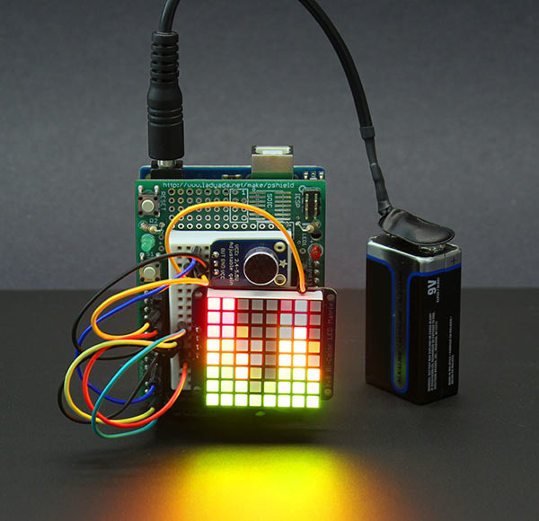
z-wave - Vera -> Domoticz
rfx - Domoticz <- MyDomoAtHome <- Imperihome
mysensors -> mysensors-gw -> Domoticz -
The electret schema is here :
http://www.edutek.ltd.uk/CBricks_Pages/Electret_Microphone.htmland IMHO the best we could use is this one:
https://www.adafruit.com/products/1063This fully assembled and tested board comes with a 20-20KHz electret microphone soldered on. For the amplification, we use the Maxim MAX4466, an op-amp specifically designed for this delicate task! The amplifier has excellent power supply noise rejection, so this amplifier sounds really good and isn't nearly as noisy or scratchy as other mic amp breakouts we've tried! This breakout is best used for projects such as voice changers, audio recording/sampling, and audio-reactive projects that use FFT. On the back, we include a small trimmer pot to adjust the gain. You can set the gain from 25x to 125x. That's down to be about 200mVpp (for normal speaking volume about 6" away) which is good for attaching to something that expects 'line level' input without clipping, or up to about 1Vpp, ideal for reading from a microcontroller ADC. The output is rail-to-rail so if the sounds gets loud, the output can go up to 5Vpp!Why do we need an FFT afterward ?
Using the normal Arduino analogRead() function would be much too slow for sampling audio. Instead, a feature of the microcontroller’s analog-to-digital converter called free-run mode is utilized. This automatically takes repeated analog samples at precise intervals…about 9.6 KHz for this project, the maximum a 16 MHz Arduino can handle with 10-bit samples. The raw audio samples are converted into a frequency spectrum using a fast Fourier transform or FFT. There are a number of Arduino FFT libraries out there, but we keep finding ourselves returning to the venerable ELM-ChaN ffft library for its speed and good looks. The FFT output still needs a bit of massaging to make for a good presentation on the limited 8x8 matrix. Several tables of scales and weights de-emphasize certain frequency ranges as they’re reduced to just eight columns. The software works at keeping the graph interesting, but some columns will always be less lively than others, especially comparing live speech against music of varying genres. If everything seems to stick toward one end of the graph, try another musician, musical genre, or different speakers. Finally, because ADC registers are accessed directly, specific interrupts are used, and the FFT code is in AVR assembly language, this software will not run on upscale boards like the Arduino Due, ChipKIT or Teensy 3.0. It is strictly for “classic” Arduinos.@epierre said:
Why do we need an FFT afterward ?
We don't 'need' an fft, it simply depends on your application.
An fft breaks down your audio signal into the different frequency components it is composed of.
This can be used to display a frequency-intensity chart, as shown on the pixel display in your picture.
Low frequency (bass) is usually shown on the left, high frequency (treble) on the right.