Easy/Newbie PCB for MySensors
-
@sincze - that sounds strange.
Is it the same sensor or could the dallas sensor be broken?
Can you see anything in the debug/serial? /(Sometimes you can see -127 and so).@sundberg84 Strange thing is.. If I unplug the temp cable from the PCB and plug it into the NANO the sketch detects the sensor. The exact same sketch on the mini says "0 sensors found" as I just print the number of sensors detected.
For debugging purposes If I would solder the resistor on the PCB and I have a different temp sensor with resistor within the cabling. Would that hurt (double resistors) ?
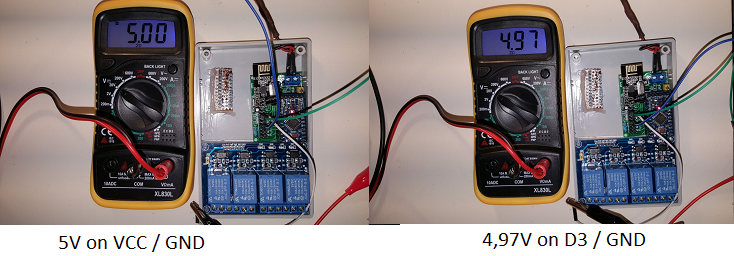
Would I have to look for a specific voltage between D3 and GND ? -
@sundberg84 Strange thing is.. If I unplug the temp cable from the PCB and plug it into the NANO the sketch detects the sensor. The exact same sketch on the mini says "0 sensors found" as I just print the number of sensors detected.
For debugging purposes If I would solder the resistor on the PCB and I have a different temp sensor with resistor within the cabling. Would that hurt (double resistors) ?
Would I have to look for a specific voltage between D3 and GND ?@sincze - so it sounds like you have issues between pcb connector and A0 pin on the atmega328. You could try to do a continuitytest between that - and check soldering job on the MysX connector and on the back on the pro mini (A0)
Controller: Proxmox VM - Home Assistant
MySensors GW: Arduino Uno - W5100 Ethernet, Gw Shield Nrf24l01+ 2,4Ghz
MySensors GW: Arduino Uno - Gw Shield RFM69, 433mhz
RFLink GW - Arduino Mega + RFLink Shield, 433mhz -
@sincze - so it sounds like you have issues between pcb connector and A0 pin on the atmega328. You could try to do a continuitytest between that - and check soldering job on the MysX connector and on the back on the pro mini (A0)
@sundberg84 Just for the check A0 or D3 (temp sensor)?
As A0 is working, I have a relais attached to it. ;) -
@sundberg84 Just for the check A0 or D3 (temp sensor)?
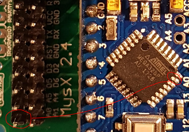
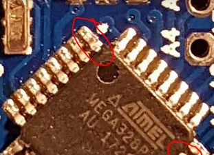
As A0 is working, I have a relais attached to it. ;)@sincze sorry - my misstake, D3 offcourse. You can do if from D3 on the MysX connector to D3 on the atmega chip. D3 on the cjip is the upper left pin on the image.
Controller: Proxmox VM - Home Assistant
MySensors GW: Arduino Uno - W5100 Ethernet, Gw Shield Nrf24l01+ 2,4Ghz
MySensors GW: Arduino Uno - Gw Shield RFM69, 433mhz
RFLink GW - Arduino Mega + RFLink Shield, 433mhz -
@sincze sorry - my misstake, D3 offcourse. You can do if from D3 on the MysX connector to D3 on the atmega chip. D3 on the cjip is the upper left pin on the image.
@sundberg84 yes, I have a 'beep' pffffff would a double resistor hurt ?? 1 on pcb the other one in the cable?
I tried connecting it directly to pin 3 on the arduino, no detection, I tried replacing the resistor. nothing. I tried a different temp sensors.. No detection. I moved the new temp sensor to the nano... detected.
I tried an empty Dallas temp only sketch on the mini... no detection. Well Now I'm lost ;-) -
@sundberg84 yes, I have a 'beep' pffffff would a double resistor hurt ?? 1 on pcb the other one in the cable?
I tried connecting it directly to pin 3 on the arduino, no detection, I tried replacing the resistor. nothing. I tried a different temp sensors.. No detection. I moved the new temp sensor to the nano... detected.
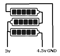
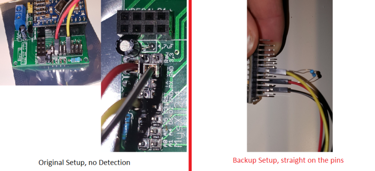
I tried an empty Dallas temp only sketch on the mini... no detection. Well Now I'm lost ;-)@sincze - and you use the right power source on the PCB? (VCC = 5v and 3.3v = Well... 3.3v) Please send pictures of both setup as mentioned.
-
Hi Sundberg84,
I have some v8 and now enough time for playing.
I setup with v3.3 2xAA, booster, NRF24, simple door sensor or DHT.
1-2 week and the batteries are discharged, I hear little buzz from the mini or other components.
This is the 2nd built where I meet this problem.
Do you have any idea what component is the failed ?
thanks
Barna -
Hi Sundberg84,
I have some v8 and now enough time for playing.
I setup with v3.3 2xAA, booster, NRF24, simple door sensor or DHT.
1-2 week and the batteries are discharged, I hear little buzz from the mini or other components.
This is the 2nd built where I meet this problem.
Do you have any idea what component is the failed ?
thanks
Barna@Barna as @gohan said I suspect the booster as well. A small buzz is normally from that hardware.
Also did you implement sleep() ?Controller: Proxmox VM - Home Assistant
MySensors GW: Arduino Uno - W5100 Ethernet, Gw Shield Nrf24l01+ 2,4Ghz
MySensors GW: Arduino Uno - Gw Shield RFM69, 433mhz
RFLink GW - Arduino Mega + RFLink Shield, 433mhz -
@sundberg84 this is not normal buzz, stronger than before.
I have used this source only: https://www.ebay.com/itm/mini-DC-DC-0-8-3-3V-to-DC-3-3V-Step-UP-Boost-Power-Module-For-Breadboard-Arduino-/281556288481?hash=item418e1003e1
which another part could make the buzz ?
yes, I use sleep
sleep(1, CHANGE, SLEEP_TIME); SLEEP_TIME is 900000 , but the node does not wake up and send the battery status, only when door sensor changes.
No, I have not removed the led and regulator, this is the testing period only :) -
Hi Sundberg84,
I have some v8 and now enough time for playing.
I setup with v3.3 2xAA, booster, NRF24, simple door sensor or DHT.
1-2 week and the batteries are discharged, I hear little buzz from the mini or other components.
This is the 2nd built where I meet this problem.
Do you have any idea what component is the failed ?
thanks
Barna -
@sincze - and you use the right power source on the PCB? (VCC = 5v and 3.3v = Well... 3.3v) Please send pictures of both setup as mentioned.
@sundberg84 @dbemowsk Thank you guys for still trying to help me. I almost gave up on using a Dallas Termp sensor o n a pro mini. As said I even tried connecting the temp sensor directly to the pins with same results. If I connect the pins to my nano, it is being detected and transmitting temp values. I even used a different sketch.. Just for the temp sensor. link found_here. Changed it to use Pin 3 ofcourse. I even connected the whole thing to D2 (resistor back in the wires)... without being succesful either.
-
@sundberg84 @dbemowsk Thank you guys for still trying to help me. I almost gave up on using a Dallas Termp sensor o n a pro mini. As said I even tried connecting the temp sensor directly to the pins with same results. If I connect the pins to my nano, it is being detected and transmitting temp values. I even used a different sketch.. Just for the temp sensor. link found_here. Changed it to use Pin 3 ofcourse. I even connected the whole thing to D2 (resistor back in the wires)... without being succesful either.
@sincze Are you sure you sure you got correct power on the GND and VCC pins on the MySX connector?
Vera Plus running UI7 with MySensors, Sonoffs and 1-Wire devices
Visit my website for more Bits, Bytes and Ramblings from me: http://dan.bemowski.info/ -
@sincze Are you sure you sure you got correct power on the GND and VCC pins on the MySX connector?
-
Dallas temp sensors needs 3.3v VCC if I remember right. Not 5v.
Controller: Proxmox VM - Home Assistant
MySensors GW: Arduino Uno - W5100 Ethernet, Gw Shield Nrf24l01+ 2,4Ghz
MySensors GW: Arduino Uno - Gw Shield RFM69, 433mhz
RFLink GW - Arduino Mega + RFLink Shield, 433mhz -
Dallas temp sensors needs 3.3v VCC if I remember right. Not 5v.
@sundberg84 haha yes i was wondering that myself so tried it connecting it to 3,3v as well. However on the 5v nano working just fine. Technical specs tell me: Power supply range is 3.0V to 5.5V
also mysensors link
Pretty strange huh. -
@sundberg84 haha yes i was wondering that myself so tried it connecting it to 3,3v as well. However on the 5v nano working just fine. Technical specs tell me: Power supply range is 3.0V to 5.5V
also mysensors link
Pretty strange huh.@sincze my mistake. Really strange this... Should work just fine. Can you upload a better resolution picture of your hardware and the sketch you are using?
-
@sundberg84 haha yes i was wondering that myself so tried it connecting it to 3,3v as well. However on the 5v nano working just fine. Technical specs tell me: Power supply range is 3.0V to 5.5V
also mysensors link
Pretty strange huh.@sincze I have 10 of these DS18B20s strung over approximately 12m monitoring all rooms on both floors of my house and two side lofts, all running on 3.22v from a Pro-Mini. Never have skipped a beat, reporting every 5 minutes, well, aside from a telephone socket which pins went walkabout (the chips are crimped to RJ11s).
There is something not right with the physical arrangement if you can get the same circuit to report at 5v...