Easy/Newbie PCB for MySensors
-
Hi All!
Could someone suggest me an elegant way to extend the mysx connector? SO i would like to multiple the A4 A5 pins onto another prototype board to use more I2C devices....
@tommas just add a wire on the back side to the prototyping area ? You could design a MysX daughter board as well 😉
-
@tommas just add a wire on the back side to the prototyping area ? You could design a MysX daughter board as well 😉
Unofrtunately i havent got the skills and free time for a daughter board.:(. But doesnt have someone else a daughterboard?:)
-
@tommas just add a wire on the back side to the prototyping area ? You could design a MysX daughter board as well 😉
Or have you got any suggestion expansion board for arduino mini pro ? Something like this: arduino-pro-mini-undershield (but it can not buy on ebay)
-
Or have you got any suggestion expansion board for arduino mini pro ? Something like this: arduino-pro-mini-undershield (but it can not buy on ebay)
@tommas how about a wire to the prototyping area ?
-
Or have you got any suggestion expansion board for arduino mini pro ? Something like this: arduino-pro-mini-undershield (but it can not buy on ebay)
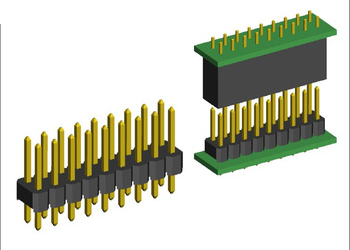
@tommas you could easily take a piece of prototyping PCB like this and create your own daughter/prototyping board if you need more space than the prototyping area has.
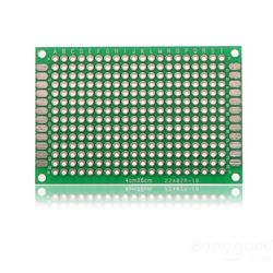
Use a set of connectors like this to connect to the MysX connector on the easy newbie board.
-
I have plans for MYSX connector daughter boards, maybe if you tell me more about what you are planning to use I can adapt.
-
Hi community!
i just got to fiddle around with my new newbie pcb and i ran into some problems.
I am already quite familiar with mysensors as i have built quite a couple of different nodes which are working very well (all on bread boards or selfmade pcb boards)
No i wanted to step up a bit and bought the newbie pcb boards.
I want to have a battery powered setup. So i did solder all the parts on the board. checked my wiring many times and also checked all components. I even did check the whole pcb board if every line is ok with a multimeter.So my problem is:
all the time i debug my node (mockup sketch) with the Arduino IDE powered by battery, stable power source etc i end up having the error TSP failed.when i leave my set up as is (i solders headers to the board to conveniently change the components ) and only power the NRF24 seperatly i get no errors. So it must be something with my power ?
but i don't get it where exactly my problem lies.
Could somebody help me? -
Hi community!
i just got to fiddle around with my new newbie pcb and i ran into some problems.
I am already quite familiar with mysensors as i have built quite a couple of different nodes which are working very well (all on bread boards or selfmade pcb boards)
No i wanted to step up a bit and bought the newbie pcb boards.
I want to have a battery powered setup. So i did solder all the parts on the board. checked my wiring many times and also checked all components. I even did check the whole pcb board if every line is ok with a multimeter.So my problem is:
all the time i debug my node (mockup sketch) with the Arduino IDE powered by battery, stable power source etc i end up having the error TSP failed.when i leave my set up as is (i solders headers to the board to conveniently change the components ) and only power the NRF24 seperatly i get no errors. So it must be something with my power ?
but i don't get it where exactly my problem lies.
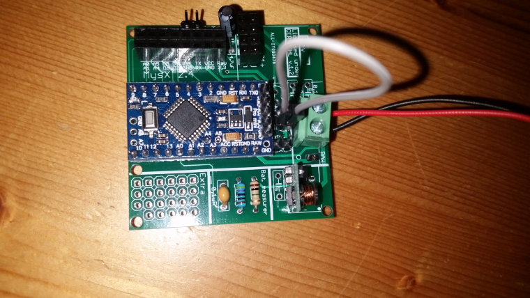
Could somebody help me?@helvetian - hi, sure we can help!
But it would be much easier if you described your hardware setup (picture?) and logs.
The EasyPCB is versatile so you can use it in many ways, but a wrong combination can make it not work.
Do you use a DC-DC booster? Batteries? Which jumpters did you solder? And so on...Did you by any chance connect both batteries and ftdi Vcc at the same time?
-
thx for your fast reply. i'm in the train right now. so i can't provide you now with any pics. as soon as possible i will do that!
I am using a battery booster (as it seems the same as you use), i have the battery jumpers connected, all the resistors and caps for the battery measurement.
It is just wired that it functions while the nrf24 is powered separately. maybe i got some bad radios?
One more question: the cap just below the booster. is this necessary to reduce the noice for the radio? might that help and if yes what size do you recommend? i didn't solder any cap yet there."Did you by any chance connect both batteries and ftdi Vcc at the same time?"
Yes! I did try this as well. Same results...
I should also mention i got my Arduino Pro mini battery powered hacked. So no more LED and Voltage regulator. But then again i also tried it with a untouched one. -
thx for your fast reply. i'm in the train right now. so i can't provide you now with any pics. as soon as possible i will do that!
I am using a battery booster (as it seems the same as you use), i have the battery jumpers connected, all the resistors and caps for the battery measurement.
It is just wired that it functions while the nrf24 is powered separately. maybe i got some bad radios?
One more question: the cap just below the booster. is this necessary to reduce the noice for the radio? might that help and if yes what size do you recommend? i didn't solder any cap yet there."Did you by any chance connect both batteries and ftdi Vcc at the same time?"
Yes! I did try this as well. Same results...
I should also mention i got my Arduino Pro mini battery powered hacked. So no more LED and Voltage regulator. But then again i also tried it with a untouched one.@helvetian - good, sounds like a good start.
If you have a booster + battery jumper in place this powers the radio separately. The most critical capacitor is the one close to VCC/GND on the Nrf24 radio. What value do you use here? Sometimes it helps to try higher values. I use 4,7 in normal cases but sometimes I either replace it or add in parallel a 47uF as well.maybe i got some bad radios?
This is not uncommon... noice from the booster (also common) combined with a bad radio might do this.
One more question: the cap just below the booster. is this necessary to reduce the noice for the radio?
Yes and No - I dont have any hard evidence (there are caps on the booster itself) but I have had good results with a 0,1 cheramic cap for a node that didnt work. It doesnt hurt to add.
"Did you by any chance connect both batteries and ftdi Vcc at the same time?"
Yes! I did try this as well. Same results...Dont do this - only 1 Vcc allowed :)
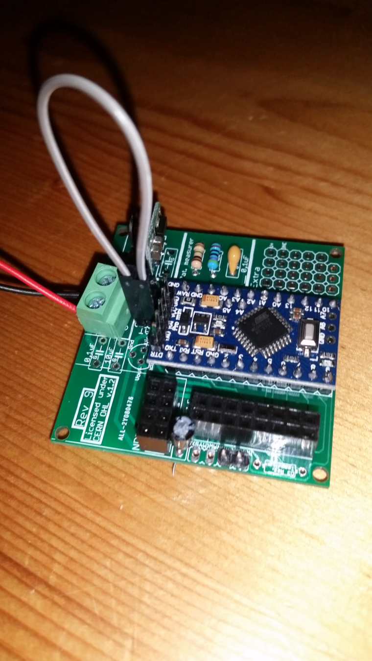
When you have the time, upload a picture - it will probably help us more to help you.
-
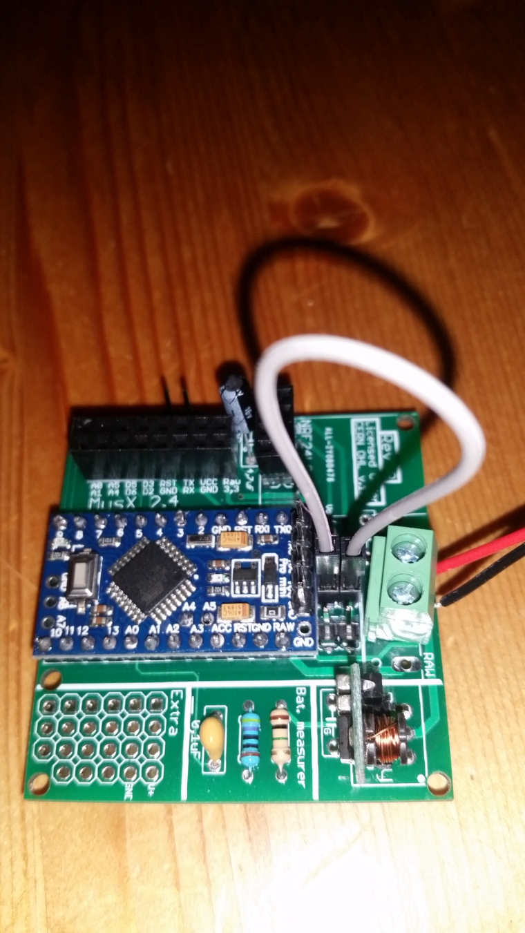
@helvetian looks good! Nice work.
I would start by soldering in/change capacitor on the radio and booster as mentioned. Try some other radio of you have. I have never connected the jumper for irq so just to test of nothing else works you can de-solder the irq jumper. -
ok. thanks for the tips and your promt assistance! such a great community!
i will try to experiment with some caps.
i tested already a couple of different radios. but maybe i will get once a decent one which will work -
get some of these, I am very happy I got them
https://www.aliexpress.com/item/Free-shipping-100PCS-Multilayer-ceramic-capacitor-10UF-106-50V-P-5-08mm/32783039097.html@gohan
just bought them on ali. What would you recommend in the meantime till they arrive here in snowy switzerland? i got a assortement of electrolyt caps.
i got a bunch of 0.1uf ceramics. could i just solder(or test it on a breadboard) 10 of them to try out? -
just a quick update.
i ran some more tests with different radios and a 10uf electroltyte cap on the booster. And some different batteries.
Heureka! It works. For now. It is running now with a 3.7v lipo battery without the voltage regulator. Does anybody know if this is safe in the long run? -
If you bypassed the booster and that works it seems like you have a booster which generates alot of noice. Try bypassing it with 2xaa and see what happens.