Easy/Newbie PCB for MySensors
-
@achurak1 do you know you could modify the pir sensor to work directly from batteries by removing the regulator?
@gohan - I tried to connect the 3.3v to one of the three pins where you'd usually put a jumper (H, L pads) as I've seen people discussing it on this forum and it just didn't work for me, the sensor did work, but very unstable, would fire up every time radio sends or receives something.
-
Because you need to add an extra AA battery to increase voltage to around 4,5v just for the pir sensor
@gohan - not sure how exactly it answers my question? I thought you meant I could run the pir from 3.3v. I could plug everything to an outlet and don't worry about the batteries at all. The pir works perfectly from two batteries and the 5v booster, so why would I want to add more batteries and make the whole thing much bigger?
-
Im doing a new revision here with RFM69 support.
I never used the RFM69 though - is there anything I should take in mind?- Is it the same with IRQ as Nrf24l01+ - not used, but good to have ie. should i have a jumper so the user can connect IRQ ?
- The antenna, is it enough with a jumper/hole so the user can solder a antenna of their own? Or is the trace/trace-length also included as the antenna?
-
The problem with rfm69 is that they work on 3 different frequencies, so you have to choose which frequency you want to support. I'm not sure if the correct length for the 433mhz is good also for the 866mhz. Let's hope somebody more expert shows up 😀
-
The problem with rfm69 is that they work on 3 different frequencies, so you have to choose which frequency you want to support. I'm not sure if the correct length for the 433mhz is good also for the 866mhz. Let's hope somebody more expert shows up 😀
@gohan - You mean with the antenna? (But the footprint is the same?)
Well, if the trace isnt added to the lenght of the antenna and I add a through-hole the user can just add what kind of lenght they want? -
The trace adds up to the antenna lengths for what I have seen so far, so I'd say to play safe and leave a hole where to solder the wire antenna or even better if it's near the edge of the pcb you could design a place to mount a sma connector for a real antenna. What do you think?
-
The trace adds up to the antenna lengths for what I have seen so far, so I'd say to play safe and leave a hole where to solder the wire antenna or even better if it's near the edge of the pcb you could design a place to mount a sma connector for a real antenna. What do you think?
@gohan - the problem is then if you buy a antenna from ebay with the right length. Added to the PCB trace the length will not match. I have to make the antenna hole as close as possible to the module then.
-
by looking around at other PCBs with sma connectors, they are close to radio module, but still a few millimeters away so I'd say you should be ok
@gohan - notised that as well. I have asked scalz over PM about this, I saw he made alot of RFM projects.
-
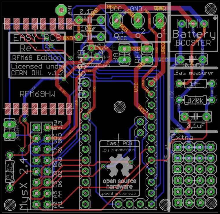
Sneak-peak at upcoming RFM edition.
All input appreciated as usual.- I couldnt fit a SMA connector at this point for external antenna because I dont want to remodel the PCB completley.
I want it to be as close looking to the original as possible to make it easier for newbies. - I went with the HW/W version. I talked to scalz and the CW is smaller and better for low power but HW/W is the one at MySensors website/tutorial/shop and preffered at 5v...
Thoughts?
- I couldnt fit a SMA connector at this point for external antenna because I dont want to remodel the PCB completley.
-
I thought the SMA connector could fit on the side of the PCB... oh well....
Btw, is the CW really smaller? I thought it was only a different pinout@gohan - Could be - never used them :S I just checked this image and they look smaller: https://www.google.se/search?q=RFM69H&source=lnms&tbm=isch&sa=X&ved=0ahUKEwjdzPDD2OTTAhWqK5oKHW5RCboQ_AUICygC&biw=1920&bih=941#tbm=isch&q=RFM69H+pinout&imgrc=c_R-Nh2VtBGlRM:
Im giving it a second try with the SMA tonight... I will rotate it 180dgr and maybe I can fit it there...
-
What is the purpose of the Raw connection under the radio connection? Designed for a jumper to supply RAW to MYSX connection?
Also any other caveats to be aware of when using RAW and a 3.3 mini and skipping the regulator? -
I was working on a project last night and was using an old REV 8 board for it. After wiring it up I needed to check some things with the pins on the breakout header. When I looked at the site, which showed the REV 9 board, I noticed that the breakout header is quite different between the REV 8 and REV 9 boards. I figured that it was worth noting to people here to watch what diagram you are looking at compared to what REV of the board you are using.
Vera Plus running UI7 with MySensors, Sonoffs and 1-Wire devices
Visit my website for more Bits, Bytes and Ramblings from me: http://dan.bemowski.info/ -
I was working on a project last night and was using an old REV 8 board for it. After wiring it up I needed to check some things with the pins on the breakout header. When I looked at the site, which showed the REV 9 board, I noticed that the breakout header is quite different between the REV 8 and REV 9 boards. I figured that it was worth noting to people here to watch what diagram you are looking at compared to what REV of the board you are using.
@dbemowsk - thank you for pointing this out!
Rev 8 is MysX 1.X and one of the reasons I upgraded to Rev 9 is because MysX 2.X came out. The pins are a bit changed but much better in MysX 2.X. For more details can study the changes.txt as well in the project.I will add this to Q&A for EasyPCB so other users dont miss it!
Thanks again! -
Hi All,
I have a lot of these PCBs in Rev.9 running as battery powered sensors. Also some with regulated power. They are running currentl with a NRF24L01. But i need to use on some sensors a RFM69 868 Radio. I have few breakout boards to use a RFM69 on a NRF24L01 connector. Is it possilbe just to replace the Radios on my EasyPBCs NRF to use RFM69 Radios? Think from power perspective should this be working. Well I know I have to Change also the Radio type in the Sketch. But is there anything more to do? Like cabling or specific Settings in the Sketch?Many Thanks
Markus -
@Markus. Keep in mind that the RFM69 radio pins are not 5V tolerable so use them only with 3.3V Pro mini. And like you said change the radio type in sketch.
@korttoma yes i use the pro mini 3,3V but can Ireplace the Radios simply with a modification of the Sketch ? Because hen I Flash following Sketch to the Easy pcb:
// Sample RFM69 receiver/gateway sketch, with ACK and optional encryption, and Automatic Transmission Control
// Passes through any wireless received messages to the serial port & responds to ACKs
// It also looks for an onboard FLASH chip, if present
// **********************************************************************************
// Copyright Felix Rusu 2016, http://www.LowPowerLab.com/contact
// **********************************************************************************
// License
// **********************************************************************************
// This program is free software; you can redistribute it
// and/or modify it under the terms of the GNU General
// Public License as published by the Free Software
// Foundation; either version 3 of the License, or
// (at your option) any later version.
//
// This program is distributed in the hope that it will
// be useful, but WITHOUT ANY WARRANTY; without even the
// implied warranty of MERCHANTABILITY or FITNESS FOR A
// PARTICULAR PURPOSE. See the GNU General Public
// License for more details.
//
// Licence can be viewed at
// http://www.gnu.org/licenses/gpl-3.0.txt
//
// Please maintain this license information along with authorship
// and copyright notices in any redistribution of this code
// **********************************************************************************
#include <RFM69.h>         //get it here: https://www.github.com/lowpowerlab/rfm69
#include <RFM69_ATC.h>     //get it here: https://www.github.com/lowpowerlab/rfm69
#include <SPIFlash.h>      //get it here: https://www.github.com/lowpowerlab/spiflash
#include <SPI.h>           //included with Arduino IDE install (www.arduino.cc)

//*********************************************************************************************
//************ IMPORTANT SETTINGS - YOU MUST CHANGE/CONFIGURE TO FIT YOUR HARDWARE *************
//*********************************************************************************************
#define NODEID        1    //unique for each node on same network
#define NETWORKID     100  //the same on all nodes that talk to each other
//Match frequency to the hardware version of the radio on your Moteino (uncomment one):
//#define FREQUENCY     RF69_433MHZ
#define FREQUENCY     RF69_868MHZ
//#define FREQUENCY     RF69_915MHZ
#define ENCRYPTKEY    "sampleEncryptKey" //exactly the same 16 characters/bytes on all nodes!
#define IS_RFM69HW_HCW  //uncomment only for RFM69HW/HCW! Leave out if you have RFM69W/CW!
//*********************************************************************************************
//Auto Transmission Control - dials down transmit power to save battery
//Usually you do not need to always transmit at max output power
//By reducing TX power even a little you save a significant amount of battery power
//This setting enables this gateway to work with remote nodes that have ATC enabled to
//dial their power down to only the required level
#define ENABLE_ATC    //comment out this line to disable AUTO TRANSMISSION CONTROL
//*********************************************************************************************
#define SERIAL_BAUD   115200

#ifdef __AVR_ATmega1284P__
  #define LED           15 // Moteino MEGAs have LEDs on D15
  #define FLASH_SS      23 // and FLASH SS on D23
#else
  #define LED           9 // Moteinos have LEDs on D9
  #define FLASH_SS      8 // and FLASH SS on D8
#endif

#ifdef ENABLE_ATC
  RFM69_ATC radio;
#else
  RFM69 radio;
#endif

SPIFlash flash(FLASH_SS, 0xEF30); //EF30 for 4mbit  Windbond chip (W25X40CL)
bool promiscuousMode = false; //set to 'true' to sniff all packets on the same network

void setup() {
  Serial.begin(SERIAL_BAUD);
  delay(10);
  radio.initialize(FREQUENCY,NODEID,NETWORKID);
#ifdef IS_RFM69HW_HCW
  radio.setHighPower(); //must include this only for RFM69HW/HCW!
#endif
  radio.encrypt(ENCRYPTKEY);
  radio.promiscuous(promiscuousMode);
  //radio.setFrequency(919000000); //set frequency to some custom frequency
  char buff[50];
  sprintf(buff, "\nListening at %d Mhz...", FREQUENCY==RF69_433MHZ ? 433 : FREQUENCY==RF69_868MHZ ? 868 : 915);
  Serial.println(buff);
  if (flash.initialize())
  {
    Serial.print("SPI Flash Init OK. Unique MAC = [");
    flash.readUniqueId();
    for (byte i=0;i<8;i++)
    {
      Serial.print(flash.UNIQUEID[i], HEX);
      if (i!=8) Serial.print(':');
    }
    Serial.println(']');

    //alternative way to read it:
    //byte* MAC = flash.readUniqueId();
    //for (byte i=0;i<8;i++)
    //{
    //  Serial.print(MAC[i], HEX);
    //  Serial.print(' ');
    //}
  }
  else
    Serial.println("SPI Flash MEM not found (is chip soldered?)...");

#ifdef ENABLE_ATC
  Serial.println("RFM69_ATC Enabled (Auto Transmission Control)");
#endif
}

byte ackCount=0;
uint32_t packetCount = 0;
void loop() {
  //process any serial input
  if (Serial.available() > 0)
  {
    char input = Serial.read();
    if (input == 'r') //d=dump all register values
      radio.readAllRegs();
    if (input == 'E') //E=enable encryption
      radio.encrypt(ENCRYPTKEY);
    if (input == 'e') //e=disable encryption
      radio.encrypt(null);
    if (input == 'p')
    {
      promiscuousMode = !promiscuousMode;
      radio.promiscuous(promiscuousMode);
      Serial.print("Promiscuous mode ");Serial.println(promiscuousMode ? "on" : "off");
    }

    if (input == 'd') //d=dump flash area
    {
      Serial.println("Flash content:");
      int counter = 0;

      while(counter<=256){
        Serial.print(flash.readByte(counter++), HEX);
        Serial.print('.');
      }
      while(flash.busy());
      Serial.println();
    }
    if (input == 'D')
    {
      Serial.print("Deleting Flash chip ... ");
      flash.chipErase();
      while(flash.busy());
      Serial.println("DONE");
    }
    if (input == 'i')
    {
      Serial.print("DeviceID: ");
      word jedecid = flash.readDeviceId();
      Serial.println(jedecid, HEX);
    }
    if (input == 't')
    {
      byte temperature =  radio.readTemperature(-1); // -1 = user cal factor, adjust for correct ambient
      byte fTemp = 1.8 * temperature + 32; // 9/5=1.8
      Serial.print( "Radio Temp is ");
      Serial.print(temperature);
      Serial.print("C, ");
      Serial.print(fTemp); //converting to F loses some resolution, obvious when C is on edge between 2 values (ie 26C=78F, 27C=80F)
      Serial.println('F');
    }
  }

  if (radio.receiveDone())
  {
    Serial.print("#[");
    Serial.print(++packetCount);
    Serial.print(']');
    Serial.print('[');Serial.print(radio.SENDERID, DEC);Serial.print("] ");
    if (promiscuousMode)
    {
      Serial.print("to [");Serial.print(radio.TARGETID, DEC);Serial.print("] ");
    }
    for (byte i = 0; i < radio.DATALEN; i++)
      Serial.print((char)radio.DATA[i]);
    Serial.print("   [RX_RSSI:");Serial.print(radio.RSSI);Serial.print("]");

    if (radio.ACKRequested())
    {
      byte theNodeID = radio.SENDERID;
      radio.sendACK();
      Serial.print(" - ACK sent.");

      // When a node requests an ACK, respond to the ACK
      // and also send a packet requesting an ACK (every 3rd one only)
      // This way both TX/RX NODE functions are tested on 1 end at the GATEWAY
      if (ackCount++%3==0)
      {
        Serial.print(" Pinging node ");
        Serial.print(theNodeID);
        Serial.print(" - ACK...");
        delay(3); //need this when sending right after reception .. ?
        if (radio.sendWithRetry(theNodeID, "ACK TEST", 8, 0))  // 0 = only 1 attempt, no retries
          Serial.print("ok!");
        else Serial.print("nothing");
      }
    }
    Serial.println();
    Blink(LED,3);
  }
}

void Blink(byte PIN, int DELAY_MS)
{
  pinMode(PIN, OUTPUT);
  digitalWrite(PIN,HIGH);
  delay(DELAY_MS);
  digitalWrite(PIN,LOW);
}
I get following result:
Listening at 868 Mhz...
SPI Flash MEM not found (is chip soldered?)...
RFM69_ATC Enabled (Auto Transmission Control)