Hydroponics (Update 1/31) w/pics
-
Hi Folks,
I've been thinking on the creation of a Hydroponics sensor to be used in the context of the MySensors network.
After some time adjusting the design for 3D printing the parts I'm starting to look at how to monitor and manage the system.
I have a rough idea of what it should monitor and do but would like the inputs from this community since there are plety of folks with experience managing gardens and plants.
Data to monitor:
-
Water PH Level - Should be kept between 5.5 and 6.5 depending on the plant
-
Water TPM/PPM - Measure the ammount of nutrients still in the water. It will also measure dirt and other solid contaminants
-
Water temperature - Cooler water holds more oxygen which seems to be important for the roots and also warmer water holds more bacteria which will also affect root health.
-
Water Level On Deposit - MAx and Min Level
-
Water Oxygen Level
Actions:
-
Circulate Water - Pump to send the water to the roots (something like 15 minutes on 15 minutes off)
-
Balance PH by adding accid or alcaline solution - Probably using 2 peristaltic liquid pumps
-
Mix/Agitate Water - When adding the PH solution it is important to mix the water - This could be achieved with the same pump and a solenoid valve sending the water to a recirculating circuit
-
Add nutrients - Add nutrient solution up to the desired PPM level bu using another peristaltic pump
-
Filter Water
-
Add water to deposit
-
Purge water from deposit
Can you think of more item to measure or possible actions?
Cheers
-
-
@barduino If you are going to automate water pumping, you need to include leak sensors to shut down pumps. Source - personal experience:scream: .
@Dwalt thank for the tip.
I was thinking on having low and high water sensor on the deposit, not sure where I would put the leak sensors.
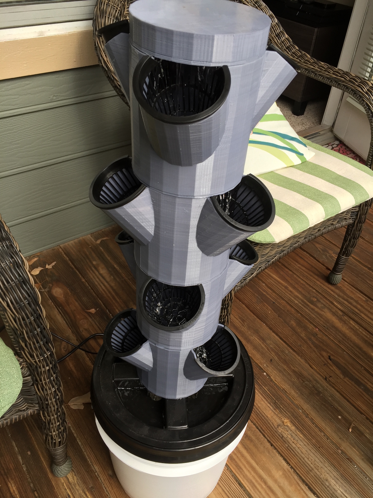
Let me give you more context, I'm trying to build something like a tower, so if it leaks it will go into the top of the deposit, perhaps I can create some sort of draining system.
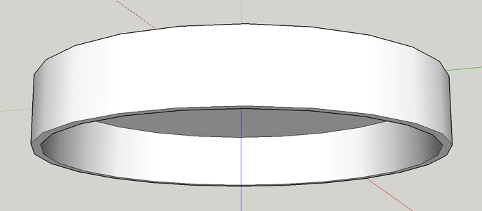
Here are some drawings
This is the top lid
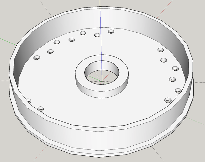
This is the top structure (the lid goes here) and it acts like a shower
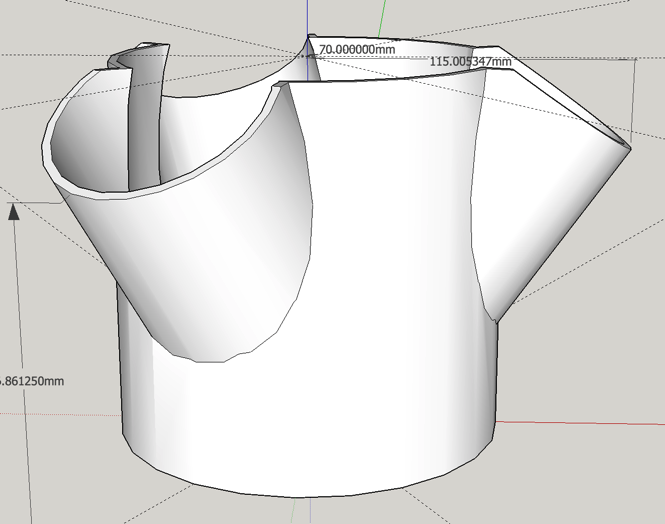
This is the main body with 3in cups version
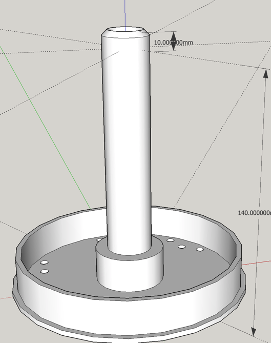
and this is the base for the body
The idea is to print bodies and bases and then one top and one lid.
The pump connects from below to the base, pumping water up to the lid which in turn will come down.
The body cup holders should be staggered.I'm thinking of creating another base to include some kind of filter and connectors to the water deposit.
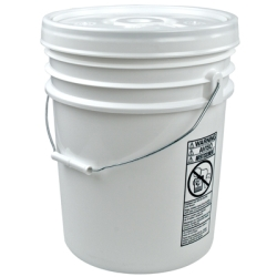
For water deposit im thinking of a 5 gallon food bucket with lid
Something like this
-
Hi Folks
Here is a first update on this project.
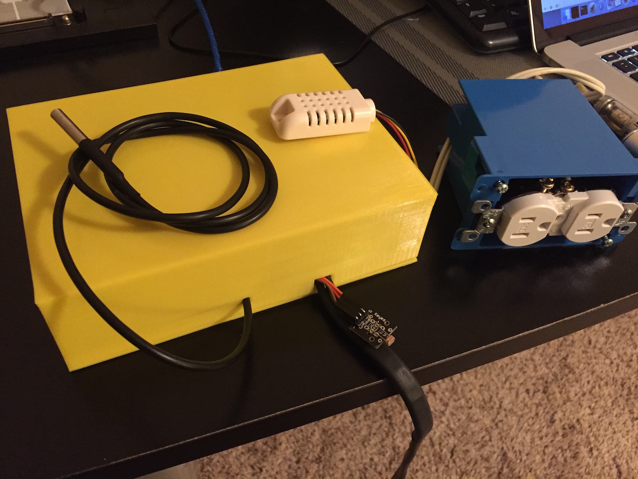
First some pictures of the hardware.
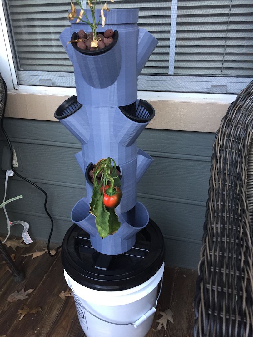
(please ignore the dying plants, they are from another experiment)The plant fountain was 100% home designed and printed and I added a 5 gallon bucket, lid and pump inside. The electronics are not connected yet.
And my development/test electronics
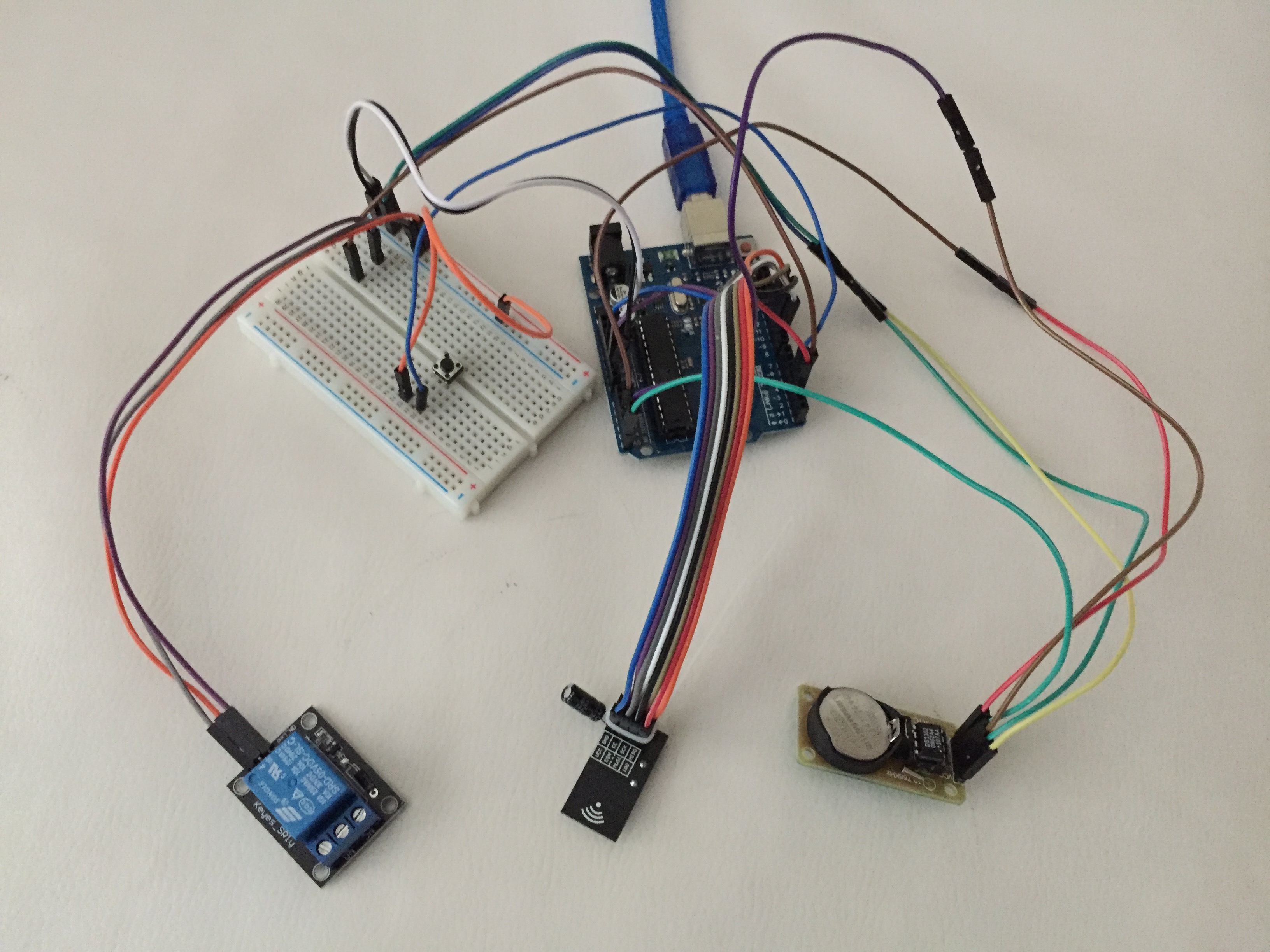
Arduino, relay for the pump and an RTC module
This will allow me to complete phase 1 which is basically running the pump for x minutes, stoping for y minutes during a time interval (e.g. 8am 6pm)
This first pump module is obviously using MySensors and although I want it to work independently of a controller i'm using MySensor to report data and implement some commands.
I've tried to do things with some architecture, using classes but C++ is still a bit of a mystery to me, so feedback is welcome as always.
The current and planned architecture goes as follows:
Hydro.ino Module
- Main Module
- Implements MySensors Library
- Updates controller on data being monitored
- Receives ad-hoc commands from controller (such as turn pump on) and sends them to the correct module
/**


**/

// Enable debug prints to serial monitor
#define MY_DEBUG

// Enable and select radio type attached
#define MY_RADIO_NRF24
//#define MY_RADIO_RFM69

// Enabled repeater feature for this node
//#define MY_REPEATER_FEATURE

// Define Node ID
#define MY_NODE_ID 7

// INCLUDES //
#include <SPI.h>
#include <MySensor.h>
#include <Bounce2.h>
#include <Time.h>
#include <DS1302RTC.h>  // A  DS3231/DS3232 library

#include "HydroConfig.h"
#include "MyPump.h"

// Skecth name and version
#define SKETCH_NAME "Hydro9"
#define SKETCH_VERSION "v0.1"

// Pin Assignments

#define BUTTON_PIN  4  // Arduino Digital I/O pin number for button

Bounce debouncer = Bounce();
int oldValue = 0;
unsigned long lastUpdate = 0;

MyMessage msgPump(MY_PUMP_ID, V_STATUS);

MyPump myPump(MY_PUMP_RELAY_PIN);
void setup()
{
  // Setup the button
  pinMode(BUTTON_PIN, INPUT);
  // Activate internal pull-up
  digitalWrite(BUTTON_PIN, HIGH);

  // After setting up the button, setup debouncer
  debouncer.attach(BUTTON_PIN);
  debouncer.interval(5);

  myPump.rtc_init();
  // Request latest time from controller at startup
  requestTime();
  wait(2000);// Wait for time form controller
  Serial.print("Current time: ");
  Serial.println(myPump.currentDateTime().c_str());
  myPump.pumpCycleRun(1);
  myPump.pumpCycleStop(1);
}

void presentation()  {
  // Send the sketch version information to the gateway and Controller
  sendSketchInfo(SKETCH_NAME, SKETCH_VERSION);

  // Register all sensors to gw (they will be created as child devices)
  present(MY_PUMP_ID, S_BINARY, "Pump");
}


void loop()
{
  debouncer.update();
  // Get the update value
  int value = debouncer.read();
  if (value != oldValue && value == 0) {
    send(msgPump.set(myPump.pumpSwitch()), false);
  }
  oldValue = value;
  if(myPump.pumpCheck())
  {
    send(msgPump.set(myPump.isOn()), false);
  }
}

void receive(const MyMessage &message) {
  // We only expect one type of message from controller. But we better check anyway.
  if (message.isAck()) {
    Serial.println("This is an ack from gateway");
  }

  if (message.type == V_STATUS) {
    // Change relay state
    if (message.getBool())
      myPump.pumpOn();
    else
      myPump.pumpOff();

    send(msgPump.set(myPump.isOn()), false);

    // Write some debug info
    Serial.print("Incoming change for sensor:");
    Serial.print(message.sensor);
    Serial.print(", New status: ");
    Serial.println(message.getBool());
  }
}

void receiveTime(unsigned long controllerTime)
{
  myPump.rtc_set(controllerTime);
}
MyPump Module:
- Handles all pump related features
- Turn pump on/off
- Check cycle to verify if pump should be on or off
- X min On, Y min Off Cycle
- Run Cycle from start time to end time (e.g. 8:00 to 18:00)
- Run Cycle based on light of day (TBI)
- Select Normal vs Circulate water (TBI) - Using solenoid valves to direct the water between the plant fountain and the bucket
Here is the pump running at 1 minute on, 1 minute off cycle
Starting sensor (RNNNA-, 1.6.0-beta)
Radio init successful.
RTC module activated

RTC Sync TieStatus: 2 timeSet 2 Ok!
send: 7-7-0-0 s=255,c=3,t=1,pt=0,l=0,sg=0,st=ok:
Current time: 2015/12/12 16:28:55
send: 7-7-0-0 s=255,c=0,t=17,pt=0,l=10,sg=0,st=ok:1.6.0-beta
send: 7-7-0-0 s=255,c=3,t=6,pt=1,l=1,sg=0,st=ok:0
send: 7-7-0-0 s=255,c=3,t=11,pt=0,l=6,sg=0,st=ok:Hydro9
send: 7-7-0-0 s=255,c=3,t=12,pt=0,l=4,sg=0,st=ok:v0.1
send: 7-7-0-0 s=1,c=0,t=3,pt=0,l=4,sg=0,st=ok:Pump
Init complete, id=7, parent=0, distance=1
2015/12/12 16:29:52 PUMP ON
send: 7-7-0-0 s=1,c=1,t=2,pt=2,l=2,sg=0,st=ok:1
2015/12/12 16:30:52  PUMP OFF
send: 7-7-0-0 s=1,c=1,t=2,pt=2,l=2,sg=0,st=ok:0
2015/12/12 16:31:52 PUMP ON
send: 7-7-0-0 s=1,c=1,t=2,pt=2,l=2,sg=0,st=ok:1
2015/12/12 16:32:52  PUMP OFF
send: 7-7-0-0 s=1,c=1,t=2,pt=2,l=2,sg=0,st=ok:0
2015/12/12 16:33:52 PUMP ON
send: 7-7-0-0 s=1,c=1,t=2,pt=2,l=2,sg=0,st=ok:1
2015/12/12 16:34:53  PUMP OFF
send: 7-7-0-0 s=1,c=1,t=2,pt=2,l=2,sg=0,st=ok:0
2015/12/12 16:35:52 PUMP ON
send: 7-7-0-0 s=1,c=1,t=2,pt=2,l=2,sg=0,st=ok:1
Again, feedback is welcome
Cheers
-
I'm very interested in doing something along these lines in the near future. I may be jumping back in here if i do, then we could develop something together that may bring others into the world of MySensors.
-
Hi Folks
I got a question for the community.
There is no Hydroponics dedicated sensor id in MySensors Lib and probably the same with the controllers out there.
What would be better:
- Have a V_CUSTOM sensor with multiple messages inside?
- Have multiple standard sensors with single type messages inside?
So for now what I need to report and manage is:
- Is pump Running (V_STATUS)
- Pump mode Off, Normal, Schedule, Daylight (V_SCENE)?
- Minutes run/stop cycle (V_LEVEL)?
- Start/End time for timer schedule (V_LEVEL)?
- Light level for Daylight schedule (V_LEVEL)?
- Pump Switch (V_STATUS)?
So far I'm using...
MyMessage msgPump(MY_PUMP_ID, V_STATUS);
MyMessage msgLight(MY_PUMP_ID, V_LEVEL);
MyMessage msgTime(MY_PUMP_ID,V_VAR1);
Thanks
-
Hi folks,
Quick update on my progress.
I was wondering how other controllers could handle this situation.
If anyone has some input I would appreciate the feedback.
Here is how I split the nodes and messages.
Had to combine V_LEVEL with other messages such as V_VOLUME in order to have 2 similar messages on the same sensor.
I wonder if "normal"controllers just treat one message one sensor?
Cheers
-
I'm not sure how your have your 'home page' configured with this data but i personally would love to have 1 single panel for this on the home page of the home automation controller/display showing the vitals (temp, pump on, light on, etc) then have it as a grouped page so you click onto it and it then displays all of this data like you have posted above as a separate control page for fine tuning.
I know this is how i would have it set up in my OpenHAB system however, I have never used Vera before so I'm not sure if you can have/configure group pages like this. Either way, I love the look of this and like i mentioned before, i will be looking to do something along these lines in 2016 hopefully. Just waiting on the price of EC Probes to come down to a reasonable price and availability.
Awesome project dude, keep up the good work!
MySensors 2.1.1
Controller - OpenHAB (Virtual Machine)
Gateway - Arduino Mega MQTT Gateway W5100 -
I'm not sure how your have your 'home page' configured with this data but i personally would love to have 1 single panel for this on the home page of the home automation controller/display showing the vitals (temp, pump on, light on, etc) then have it as a grouped page so you click onto it and it then displays all of this data like you have posted above as a separate control page for fine tuning.
I know this is how i would have it set up in my OpenHAB system however, I have never used Vera before so I'm not sure if you can have/configure group pages like this. Either way, I love the look of this and like i mentioned before, i will be looking to do something along these lines in 2016 hopefully. Just waiting on the price of EC Probes to come down to a reasonable price and availability.
Awesome project dude, keep up the good work!
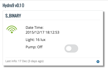
Hi @samuel235
I guess i've tried to re-invent the wheel.
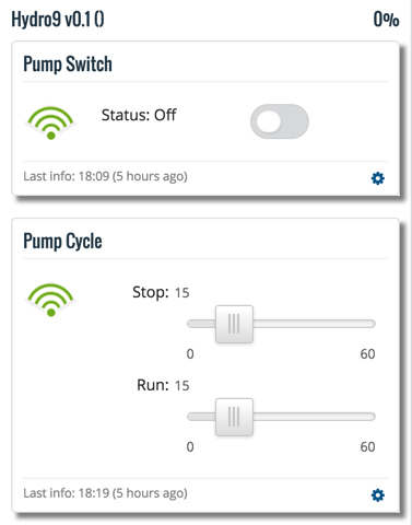
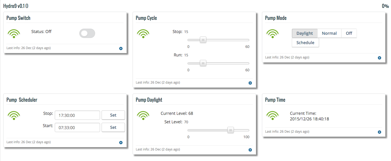
What you see is a controller developed by me. Each "card"represents a sensor with messages inside, as long as they are of different type. This seems to be a design flaw, I've made it too flexible and UI wise is a nightmare.
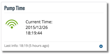
They are grouped by nodes.The image I've posted is from a phone for factor. It looks like this on anormal screen:
After this experiment, one sensor one message seems to be the way to go.
I'm also starting to experiment with openHab
Cheers
-
Hi @samuel235
I guess i've tried to re-invent the wheel.
What you see is a controller developed by me. Each "card"represents a sensor with messages inside, as long as they are of different type. This seems to be a design flaw, I've made it too flexible and UI wise is a nightmare.
They are grouped by nodes.The image I've posted is from a phone for factor. It looks like this on anormal screen:
After this experiment, one sensor one message seems to be the way to go.
I'm also starting to experiment with openHab
Cheers
-
Hi Folks,
Another update on this project
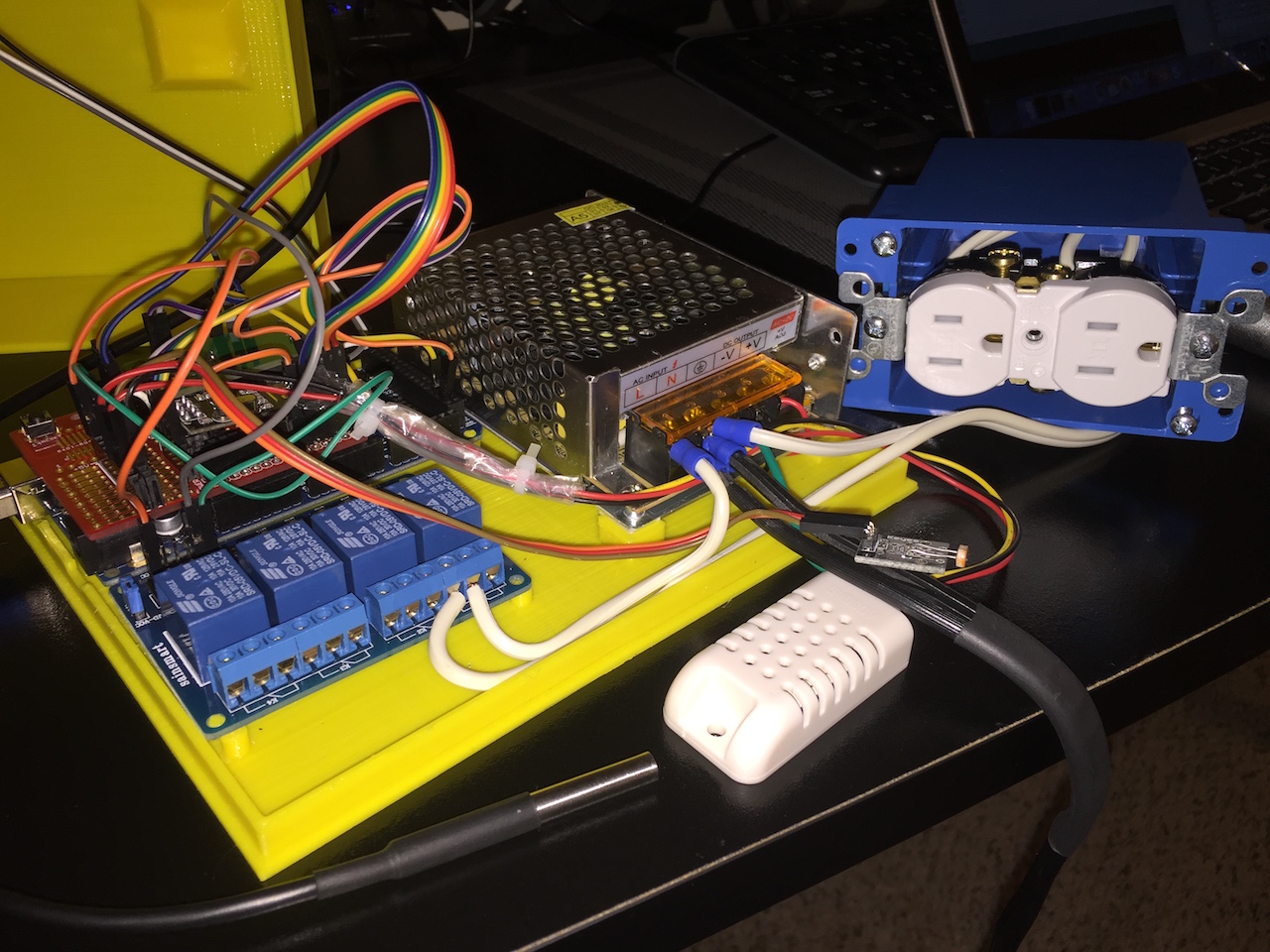
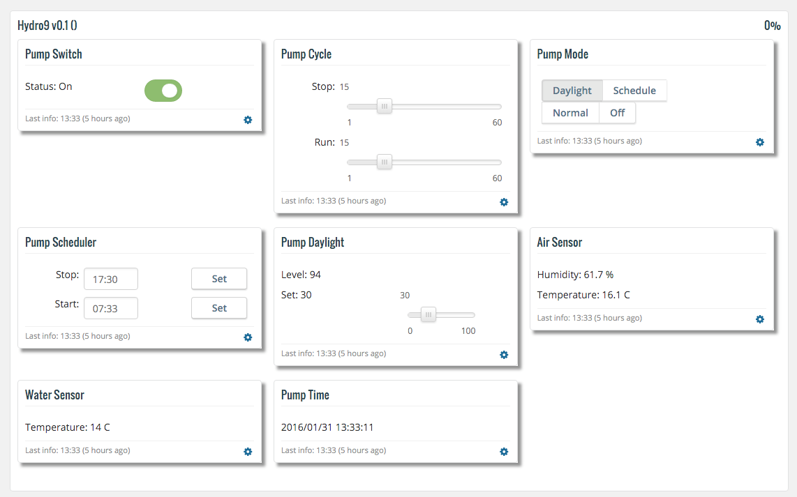
I've finally finished with the software. Added a DHT22 for air temperature and humidity and also a Dallas for the water temperature.
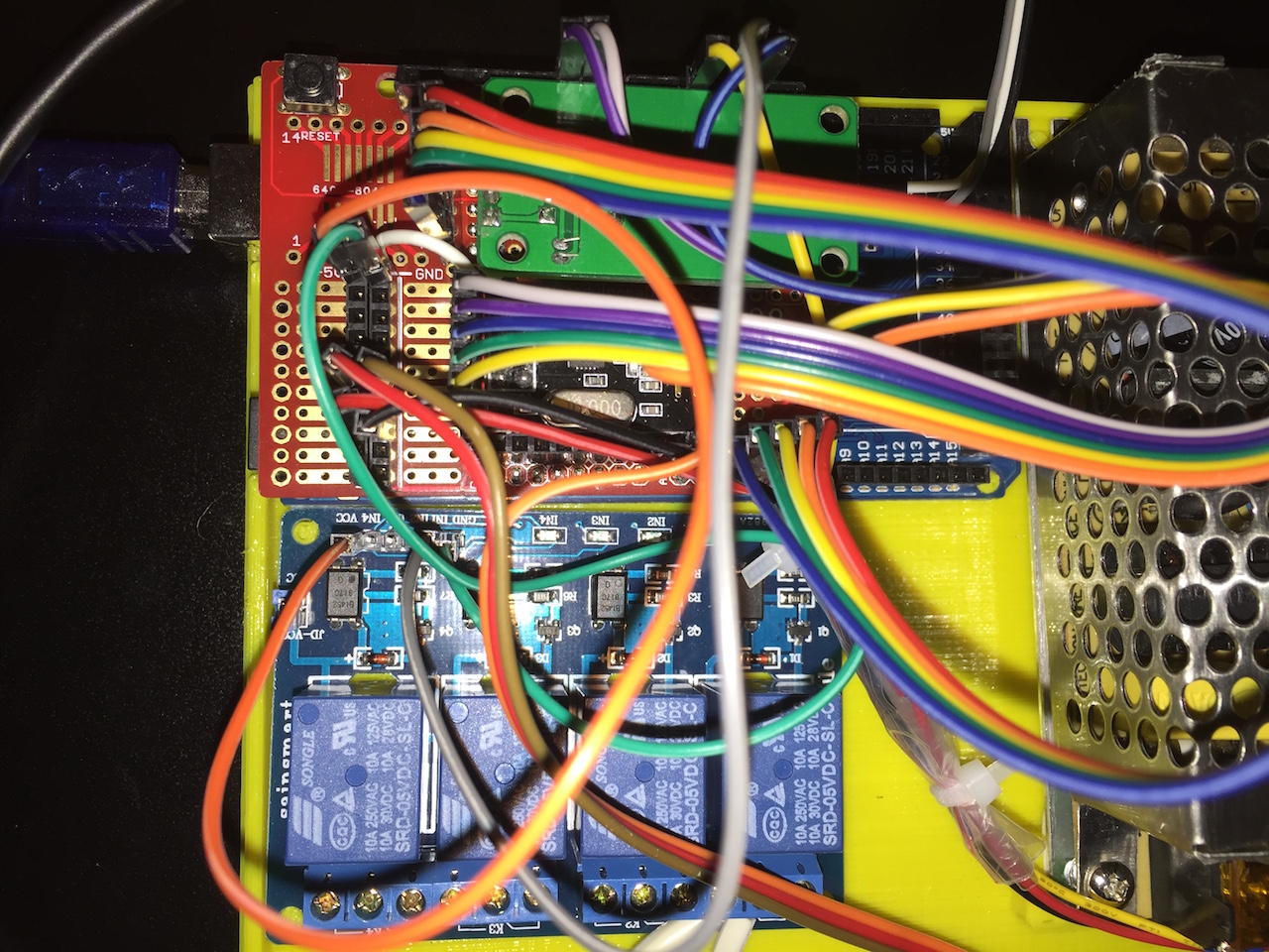
Assembling the hardware was a bit more challenging then anticipated, but with no PCB, i've decided to use a proto shield and maintain support/flexibility for both UNO and MEGA boards. Soon after I've realized the code does not fit a UNO (too much debug eventually)
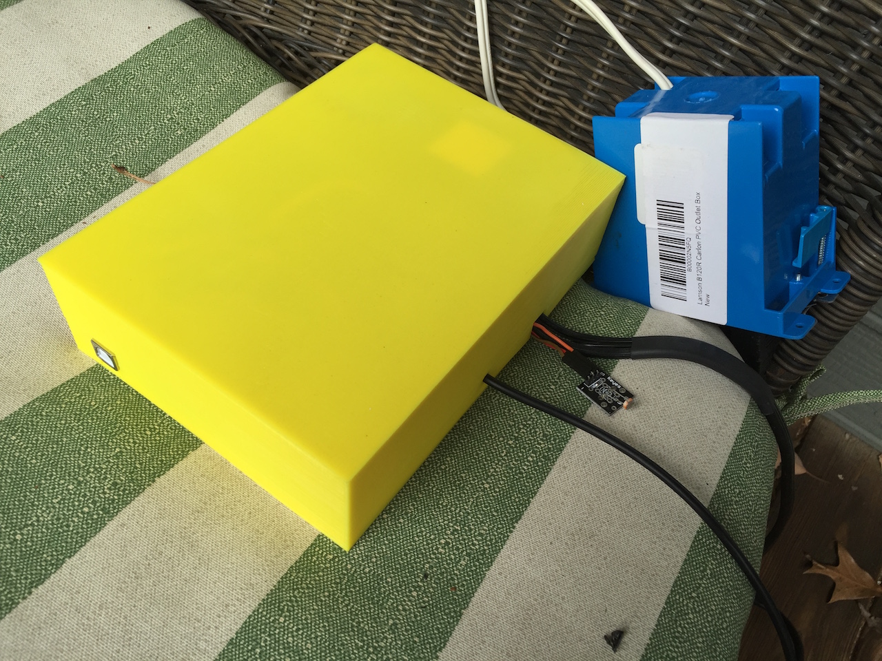
Also created a simple case to enclose it all.
The Column it self
If anyone would likr to take a look at the code, feed back is much appreciated!
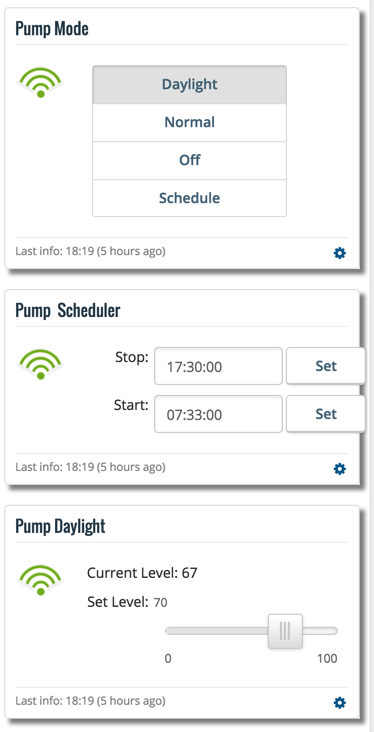
Finally the dashboard looks like this
Cheers
EDIT: Forgot to add the startup log
Starting sensor (RNNNA-, 1.6.0-beta) Radio init successful. Initializing DHT... Done! Dallas Temperature IC Control Library Demo Locating devices...Found 1 devices. Parasite power is: OFF Device 0 Address: 2817611D070000C3 Device 0 Resolution: 9 RTC module activated The DS1302 is write protected. This normal. RTC Sync TieStatus: 2 timeSet 2 Ok! send: 7-7-0-0 s=255,c=3,t=1,pt=0,l=0,sg=0,st=ok: read: 0-0-7 s=255,c=3,t=1,pt=0,l=10,sg=0:1454110229 Time value received: 1454110229 Pump Time:2016/01/29 23:30:28 send: 7-7-0-0 s=255,c=3,t=15,pt=1,l=1,sg=0,st=ok:0 send: 7-7-0-0 s=255,c=0,t=17,pt=0,l=10,sg=0,st=ok:1.6.0-beta send: 7-7-0-0 s=255,c=3,t=6,pt=1,l=1,sg=0,st=ok:0 read: 0-0-7 s=255,c=3,t=6,pt=0,l=1,sg=0:M Starting presentation send: 7-7-0-0 s=255,c=3,t=11,pt=0,l=6,sg=0,st=ok:Hydro9 send: 7-7-0-0 s=255,c=3,t=12,pt=0,l=4,sg=0,st=ok:v0.1 send: 7-7-0-0 s=1,c=0,t=3,pt=0,l=11,sg=0,st=ok:Pump Switch send: 7-7-0-0 s=2,c=0,t=23,pt=0,l=10,sg=0,st=ok:Pump Cycle send: 7-7-0-0 s=3,c=0,t=25,pt=0,l=9,sg=0,st=ok:Pump Mode send: 7-7-0-0 s=4,c=0,t=23,pt=0,l=14,sg=0,st=ok:Pump Scheduler send: 7-7-0-0 s=5,c=0,t=23,pt=0,l=13,sg=0,st=ok:Pump Daylight send: 7-7-0-0 s=6,c=0,t=6,pt=0,l=10,sg=0,st=ok:Air Sensor send: 7-7-0-0 s=7,c=0,t=6,pt=0,l=12,sg=0,st=ok:Water Sensor send: 7-7-0-0 s=10,c=0,t=23,pt=0,l=9,sg=0,st=ok:Pump Time End presentation Init complete, id=7, parent=0, distance=1 **************** PUMP STATUS *********************** Pump Mode is: Daylight Pump Cycle: On:15 Off:15 Pump Schedule: Start:07:33 Stop:17:30 Pump Daylight: Start:70 Current:59 Pump Time: 2016/01/29 23:30:34 **************************************************** ************* ENVIRONMENT STATUS ******************* Air temperature:10.60 Air humidity:37.90 Water temperature:10.00 **************************************************** send: 7-7-0-0 s=1,c=1,t=2,pt=1,l=1,sg=0,st=ok:0 send: 7-7-0-0 s=3,c=1,t=19,pt=2,l=2,sg=0,st=ok:3 send: 7-7-0-0 s=4,c=1,t=24,pt=0,l=5,sg=0,st=ok:07:33 send: 7-7-0-0 s=4,c=1,t=25,pt=0,l=5,sg=0,st=ok:17:30 send: 7-7-0-0 s=5,c=1,t=37,pt=2,l=2,sg=0,st=ok:70 send: 7-7-0-0 s=5,c=1,t=35,pt=2,l=2,sg=0,st=ok:59 send: 7-7-0-0 s=2,c=1,t=37,pt=2,l=2,sg=0,st=ok:15 send: 7-7-0-0 s=2,c=1,t=35,pt=2,l=2,sg=0,st=ok:15 send: 7-7-0-0 s=10,c=1,t=24,pt=0,l=20,sg=0,st=ok:2016/01/29 23:30:34 send: 7-7-0-0 s=6,c=1,t=0,pt=7,l=5,sg=0,st=ok:10.6 send: 7-7-0-0 s=6,c=1,t=1,pt=7,l=5,sg=0,st=ok:37.9 send: 7-7-0-0 s=7,c=1,t=0,pt=7,l=5,sg=0,st=ok:10.0 2016/01/29 23:30:34 Light level: 59 -
Hi Folks,
Another update on this project
I've finally finished with the software. Added a DHT22 for air temperature and humidity and also a Dallas for the water temperature.
Assembling the hardware was a bit more challenging then anticipated, but with no PCB, i've decided to use a proto shield and maintain support/flexibility for both UNO and MEGA boards. Soon after I've realized the code does not fit a UNO (too much debug eventually)
Also created a simple case to enclose it all.
The Column it self
If anyone would likr to take a look at the code, feed back is much appreciated!
Finally the dashboard looks like this
Cheers
EDIT: Forgot to add the startup log
Starting sensor (RNNNA-, 1.6.0-beta) Radio init successful. Initializing DHT... Done! Dallas Temperature IC Control Library Demo Locating devices...Found 1 devices. Parasite power is: OFF Device 0 Address: 2817611D070000C3 Device 0 Resolution: 9 RTC module activated The DS1302 is write protected. This normal. RTC Sync TieStatus: 2 timeSet 2 Ok! send: 7-7-0-0 s=255,c=3,t=1,pt=0,l=0,sg=0,st=ok: read: 0-0-7 s=255,c=3,t=1,pt=0,l=10,sg=0:1454110229 Time value received: 1454110229 Pump Time:2016/01/29 23:30:28 send: 7-7-0-0 s=255,c=3,t=15,pt=1,l=1,sg=0,st=ok:0 send: 7-7-0-0 s=255,c=0,t=17,pt=0,l=10,sg=0,st=ok:1.6.0-beta send: 7-7-0-0 s=255,c=3,t=6,pt=1,l=1,sg=0,st=ok:0 read: 0-0-7 s=255,c=3,t=6,pt=0,l=1,sg=0:M Starting presentation send: 7-7-0-0 s=255,c=3,t=11,pt=0,l=6,sg=0,st=ok:Hydro9 send: 7-7-0-0 s=255,c=3,t=12,pt=0,l=4,sg=0,st=ok:v0.1 send: 7-7-0-0 s=1,c=0,t=3,pt=0,l=11,sg=0,st=ok:Pump Switch send: 7-7-0-0 s=2,c=0,t=23,pt=0,l=10,sg=0,st=ok:Pump Cycle send: 7-7-0-0 s=3,c=0,t=25,pt=0,l=9,sg=0,st=ok:Pump Mode send: 7-7-0-0 s=4,c=0,t=23,pt=0,l=14,sg=0,st=ok:Pump Scheduler send: 7-7-0-0 s=5,c=0,t=23,pt=0,l=13,sg=0,st=ok:Pump Daylight send: 7-7-0-0 s=6,c=0,t=6,pt=0,l=10,sg=0,st=ok:Air Sensor send: 7-7-0-0 s=7,c=0,t=6,pt=0,l=12,sg=0,st=ok:Water Sensor send: 7-7-0-0 s=10,c=0,t=23,pt=0,l=9,sg=0,st=ok:Pump Time End presentation Init complete, id=7, parent=0, distance=1 **************** PUMP STATUS *********************** Pump Mode is: Daylight Pump Cycle: On:15 Off:15 Pump Schedule: Start:07:33 Stop:17:30 Pump Daylight: Start:70 Current:59 Pump Time: 2016/01/29 23:30:34 **************************************************** ************* ENVIRONMENT STATUS ******************* Air temperature:10.60 Air humidity:37.90 Water temperature:10.00 **************************************************** send: 7-7-0-0 s=1,c=1,t=2,pt=1,l=1,sg=0,st=ok:0 send: 7-7-0-0 s=3,c=1,t=19,pt=2,l=2,sg=0,st=ok:3 send: 7-7-0-0 s=4,c=1,t=24,pt=0,l=5,sg=0,st=ok:07:33 send: 7-7-0-0 s=4,c=1,t=25,pt=0,l=5,sg=0,st=ok:17:30 send: 7-7-0-0 s=5,c=1,t=37,pt=2,l=2,sg=0,st=ok:70 send: 7-7-0-0 s=5,c=1,t=35,pt=2,l=2,sg=0,st=ok:59 send: 7-7-0-0 s=2,c=1,t=37,pt=2,l=2,sg=0,st=ok:15 send: 7-7-0-0 s=2,c=1,t=35,pt=2,l=2,sg=0,st=ok:15 send: 7-7-0-0 s=10,c=1,t=24,pt=0,l=20,sg=0,st=ok:2016/01/29 23:30:34 send: 7-7-0-0 s=6,c=1,t=0,pt=7,l=5,sg=0,st=ok:10.6 send: 7-7-0-0 s=6,c=1,t=1,pt=7,l=5,sg=0,st=ok:37.9 send: 7-7-0-0 s=7,c=1,t=0,pt=7,l=5,sg=0,st=ok:10.0 2016/01/29 23:30:34 Light level: 59@barduino - Fantastic! I absolutely love this project of yours dude. Keep it evolving over time, make some upgrades and mods and you will be on to even more of a winner. The first thing i would advise as Revision/Version 2 would be to get that all put onto PCB's, get the footprint of the electronics small as you can, have it so the power comes into a connector on the side of the box rather than a cable running in. Then, I'd get those electronics inside of the column itself. either in the base or the top would be the obvious place to go for. Please don't stop here, its functional now, but make it a 'whole package' and you will be loved by thousands! Well, if you can class me as thousands that is.
Seriously good work though. I'm now expecting you to show us a video of everything working and integrated ;)
MySensors 2.1.1
Controller - OpenHAB (Virtual Machine)
Gateway - Arduino Mega MQTT Gateway W5100 -
@barduino - Fantastic! I absolutely love this project of yours dude. Keep it evolving over time, make some upgrades and mods and you will be on to even more of a winner. The first thing i would advise as Revision/Version 2 would be to get that all put onto PCB's, get the footprint of the electronics small as you can, have it so the power comes into a connector on the side of the box rather than a cable running in. Then, I'd get those electronics inside of the column itself. either in the base or the top would be the obvious place to go for. Please don't stop here, its functional now, but make it a 'whole package' and you will be loved by thousands! Well, if you can class me as thousands that is.
Seriously good work though. I'm now expecting you to show us a video of everything working and integrated ;)
Thanks for your enthusiastic support!!! :smiley:
The reason for the big power supply is that I intend to have 2 solenoid valves to control the water flow, one to send water to the column the other to recirculate the water in the bucket (needed when adding nutrients or adjusting the PH). Those run on 12v and can consume some amps.
The next step would be to add a water level sensor, I'll fry the pump if the water level drops to low.
The most difficult parts to get are the PH sensor and the TPM/TDS sensor, not only expensive but most of then are not designed to be permanently submerged.
In the long run I'm also planning for 3 peristaltic pumps to send nutrients, acidic solution and base solution to adjust PH and nutrients level. These often run on 12v.
The idea of getting the electronics on the column is quite interesting. It would have to be on top since the rest of the column is not water tight. I would need to find some clever way to deal with the cables.
Any way, I've just finished adding the plants. Not the ideal time to plant anything (its winter here) but the frost is gone and they say lettuce goes well with cold temperatures.
This is what it looks like week 0. We'll see how it goes.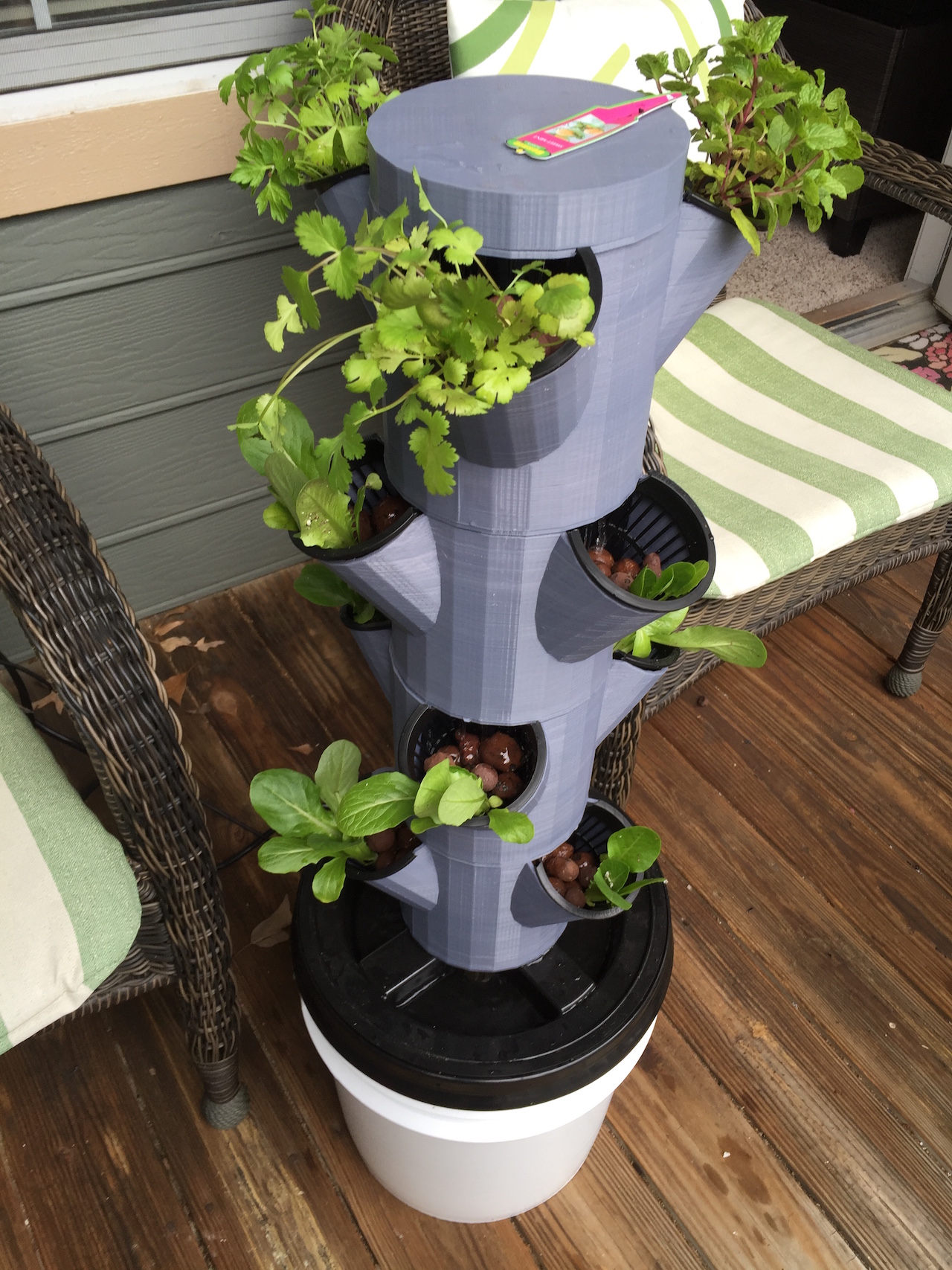
Cheers
-
Thanks for your enthusiastic support!!! :smiley:
The reason for the big power supply is that I intend to have 2 solenoid valves to control the water flow, one to send water to the column the other to recirculate the water in the bucket (needed when adding nutrients or adjusting the PH). Those run on 12v and can consume some amps.
The next step would be to add a water level sensor, I'll fry the pump if the water level drops to low.
The most difficult parts to get are the PH sensor and the TPM/TDS sensor, not only expensive but most of then are not designed to be permanently submerged.
In the long run I'm also planning for 3 peristaltic pumps to send nutrients, acidic solution and base solution to adjust PH and nutrients level. These often run on 12v.
The idea of getting the electronics on the column is quite interesting. It would have to be on top since the rest of the column is not water tight. I would need to find some clever way to deal with the cables.
Any way, I've just finished adding the plants. Not the ideal time to plant anything (its winter here) but the frost is gone and they say lettuce goes well with cold temperatures.
This is what it looks like week 0. We'll see how it goes.Cheers
@barduino - No need to explain anything about hydroponics to me, I sent myself insane with researching it in the hope to do something like this. But like you also mentioned, the cost of the PH and nutrient sensors was just too much for me right now, i can't justify that in my current situation, which is why i'm passionate and enjoying your project :)
-
Thanks for your enthusiastic support!!! :smiley:
The reason for the big power supply is that I intend to have 2 solenoid valves to control the water flow, one to send water to the column the other to recirculate the water in the bucket (needed when adding nutrients or adjusting the PH). Those run on 12v and can consume some amps.
The next step would be to add a water level sensor, I'll fry the pump if the water level drops to low.
The most difficult parts to get are the PH sensor and the TPM/TDS sensor, not only expensive but most of then are not designed to be permanently submerged.
In the long run I'm also planning for 3 peristaltic pumps to send nutrients, acidic solution and base solution to adjust PH and nutrients level. These often run on 12v.
The idea of getting the electronics on the column is quite interesting. It would have to be on top since the rest of the column is not water tight. I would need to find some clever way to deal with the cables.
Any way, I've just finished adding the plants. Not the ideal time to plant anything (its winter here) but the frost is gone and they say lettuce goes well with cold temperatures.
This is what it looks like week 0. We'll see how it goes.Cheers
@barduino I stumbled across this project a year or so ago while researching something similar to your project. There are some good resources there. I never got around to following up on it but your project is tempting me...mixing water with electronics, what's not to love.
Hello! It looks like you're interested in this conversation, but you don't have an account yet.
Getting fed up of having to scroll through the same posts each visit? When you register for an account, you'll always come back to exactly where you were before, and choose to be notified of new replies (either via email, or push notification). You'll also be able to save bookmarks and upvote posts to show your appreciation to other community members.
With your input, this post could be even better 💗
Register Login